Raspberry Pi Pico LED Shields
This is a collection of very versatile LED matrix displays due to its different resolutions and sizes, the RGB capabilities and additional buttons and joystick.
Supported Shields
Hardware
Features and Resources |
Printed Circuit Board |
5V/500㎃ up to 2.5A RGB(16×10) LED(16×10) 1
Design Data |
|
Positions
|
|---|
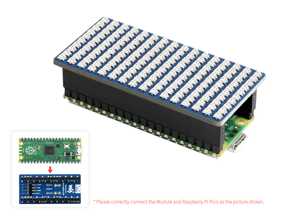
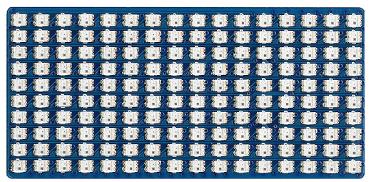
There is no separate power supply on shield! The current of this product is close to 2.5A when RGB is fully lit. It is recommended to use a power supply of 5V/3A, or more. Since the USB output current of the computer is low, software should set the brightness data at RGB555, even if the full light is only about 300㎃. Also do not set the current too low, if your brightness data is less than 4 bits, part of the light will not be bright. 16×10 WS2812B
cascaded RGB LED matrix
|
Data Sheets
Pinouts
Pin Mapping |
Pinout |
Default Zephyr Peripheral Mapping
Devicetree compatible |

|
More Samples
LED Blinky and Fade

WS2812 LED Test Pattern by PIO
See also Zephyr sample: LED strip
west build -b rpi_pico -p -S usb-console --shield waveshare_pico_rgb_led -d build/waveshare_pico_rgb_led-strip_test zephyr/samples/drivers/led_strip
west flash -r uf2 -d build/waveshare_pico_rgb_led-strip_test
west build -b rpi_pico/rp2040/w -p -S usb-console --shield waveshare_pico_rgb_led -d build/waveshare_pico_rgb_led-strip_test zephyr/samples/drivers/led_strip
west flash -r uf2 -d build/waveshare_pico_rgb_led-strip_test
west build -b waveshare_rp2040_lcd_0_96 -p -S usb-console --shield waveshare_pico_rgb_led -d build/waveshare_pico_rgb_led-strip_test zephyr/samples/drivers/led_strip
west flash -r uf2 -d build/waveshare_pico_rgb_led-strip_test
on standard 4㎆ revision
west build -b waveshare_rp2040_plus -p -S usb-console --shield waveshare_pico_rgb_led -d build/waveshare_pico_rgb_led-strip_test zephyr/samples/drivers/led_strip
west flash -r uf2 -d build/waveshare_pico_rgb_led-strip_test
on extended 16㎆ revision
west build -b waveshare_rp2040_plus@16mb -p -S usb-console --shield waveshare_pico_rgb_led -d build/waveshare_pico_rgb_led-strip_test zephyr/samples/drivers/led_strip
west flash -r uf2 -d build/waveshare_pico_rgb_led-strip_test
Simple logging output on target
***** delaying boot 4000ms (per build configuration) *****
[00:00:00.337,000] <wrn> udc_rpi: BUS RESET
[00:00:00.417,000] <wrn> udc_rpi: BUS RESET
*** Booting Zephyr OS … … … (delayed boot 4000ms) ***
[00:00:04.002,000] <inf> main: Found LED strip device rgb-led-strip
[00:00:04.002,000] <inf> main: Displaying pattern on strip
Hint
Neither LED Blinky nor LED Fade can be built and executed on Waveshare Pico RGB LED, because this shield has only digital RGB LEDs. A simple GPIO or PWM control is not possible!