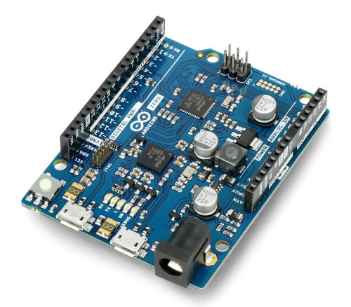
Arduino/Genuino Zero
Downstream Extension!
This board description is a copy from Zephyr with identical name and will be used for further development, improvement and preparation of changes for Zephyr within Bridle. However, the original board description still lives within the Zephyr namespace under the exactly same board name: Arduino/Genuino Zero.
Overview
The Arduino Zero is a maker-friendly development board with Atmel’s Embedded Debugger (EDBG [5]), which provides a full debug interface without the need for additional hardware.
Hardware
ATSAMD21G18A [20] ARM Cortex-M0+ processor at 48 MHz
32.768 kHz crystal oscillator
256 KiB flash memory and 32 KiB of RAM
3 user LEDs (L/Rx/Tx)
One reset button
On-board USB based EDBG unit with serial console
Native USB port
Arduino UNO R3headerArduino ICSP header
Supported Features
The arduino_zero board configuration supports the following
hardware features:
Interface |
Controller |
Driver/Component |
|---|---|---|
ADC |
on-chip |
Analogue to digital converter |
DAC |
on-chip |
Digital to analogue converter |
DMA |
on-chip |
Direct memory access |
Flash |
on-chip |
Can be used with LittleFS to store files |
GPIO |
on-chip |
I/O ports |
HWINFO |
on-chip |
Hardware info |
I2C |
on-chip |
Inter-Integrated Circuit |
NVIC |
on-chip |
nested vector interrupt controller |
PWM |
on-chip |
Pulse Width Modulation |
SPI |
on-chip |
Serial Peripheral Interface ports |
SYSTICK |
on-chip |
systick |
USART |
on-chip |
Serial ports |
USB |
on-chip |
USB device |
WDT |
on-chip |
Watchdog |
Other hardware features are not currently supported by Zephyr.
The extended default configuration can be found in the Kconfig artifact boards/extensions/zero/arduino_zero.conf. It will be add automatically to the original board default configuration in boards/arduino/zero/arduino_zero_defconfig.
Board Configurations
The arduino_zero board can be configured for the following different
use cases.
west build -b arduino_zero
Use the serial port SERCOM5 over EDBG as Zephyr console and for the shell.
west build -b arduino_zero -S usb-console
Use the native USB device port with CDC-ACM as Zephyr console and for the shell, see USB Console Snippet (usb-console).
Connections and IOs
The Arduino store [12] has detailed information about board connections. Download the Arduino Zero Schematic [14] or Arduino Zero Design Data [15] for more detail. There is also an Arduino Zero Pinout Diagram [13].
System Clock
The SAMD21 MCU is configured to use the 32.768 kHz external crystal with the on-chip PLL generating the 48 MHz system clock. The internal APB and GCLK unit are set up in the same way as the upstream Arduino libraries.
GPIO (PWM) Ports
The SAMD21 MCU has 2 GPIO ports, 3 PWM able Timer/Capture-Counter (TCC) and
2 simple Timer/Counter (TC). On the Arduino Zero, TCC2 channel 1 is
available on first user LED (L), all other user LEDs can be controlled
as GPIO. Only if CONFIG_PWM_SAM0_TCC is enabled then the
first user LED (L) is driven by TCC2 instead of by GPIO. All channels of
TCC0 and TCC1 are available on the Arduino UNO R3 header.
ADC/DAC Ports
The SAMD21 MCU has 1 DAC and 1 ADC. On the Arduino Zero the DAC voltage
output (VOUT) is available on A0 of the Arduino UNO R3 header. The ADC
channels 2-5 and 10 are available on A1-A5 of the Arduino UNO R3 header.
The external voltage reference VREFA can be used optional for the DAC and
ADC on same time and is available on AREF of the Arduino UNO R3 header.
SPI Port
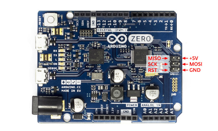
The SAMD21 MCU has 6 SERCOM based SPIs. On the Arduino Zero, SERCOM4 is
available on the 6 pin ICSP connector at the edge of the board. To the
Arduino UNO R3 header SERCOM1 is connect to external devices over D11 (MOSI),
D12 (MISO), and D13 (SCK). All signals of both busses are connected in
parallel to the Atmel EDBG.
I2C Port
The SAMD21 MCU has 6 SERCOM based I2Cs. On the Arduino Zero, SERCOM3 is signals are connected in parallel to the Atmel EDBG.
Serial Port
The SAMD21 MCU has 6 SERCOM based USARTs. One of the USARTs (SERCOM5) is
connected to the onboard Atmel Embedded Debugger (EDBG) and is the Zephyr
console. This is captured by the standard board configuration. SERCOM0 is
available on the D0 (RX) and D1 (TX) of the Arduino UNO R3 header.
USB Device Port
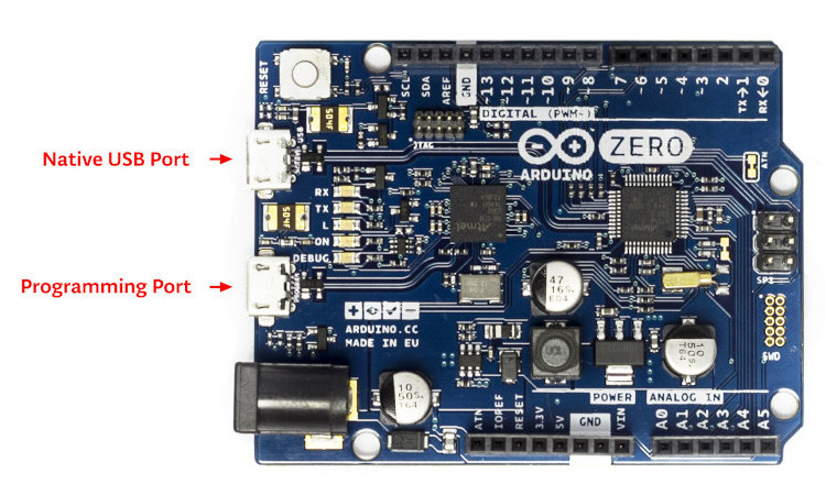
The SAMD21 MCU has a (native) USB device port that can be used to communicate with a host PC. See Zephyr USB device support samples for more, such as the USB CDC-ACM sample which sets up a virtual serial port that echos characters back to the host PC. As an alternative to the default Zephyr console on serial port the Bridle USB Console Snippet (usb-console) can be used to enable CDC ACM and switch the console to USB:
USB device idVendor=2341, idProduct=804d, bcdDevice= 3.07
USB device strings: Mfr=1, Product=2, SerialNumber=3
Product: Arduino Zero (CDC ACM)
Manufacturer: Arduino LLC
SerialNumber: 9CF503EE1D54A301
Programming and Debugging
The Arduino Zero ships the BOSSA compatible UF2 bootloader [8] also known as Arduino Zero Bootloader [16], a modern SAM-BA [7] (Boot Assistant) replacement. The bootloader can be entered by pressing the RST button twice:
USB device idVendor=2341, idProduct=004d, bcdDevice= 2.00
USB device strings: Mfr=1, Product=2, SerialNumber=0
Product: Arduino Zero
Manufacturer: Arduino LLC
Additionally, if CONFIG_USB_CDC_ACM is enabled then the
bootloader will be entered automatically when you run west flash.
Tip
When ever you need to restore this original bootloader you should read and following the directions in Arduino Zero Advanced Features [17] and Update the Bootloader on the Arduino Zero [18]. There is also a backup copy of the original bootloader together with a ready to use Segger JFlash control file inside the Bridel project:
The Segger JFlash control file is only useful when the EDBG firmware was upgrade to the latest J-Link firmware for Atmel EDBG [1]. This was a special OEM firmware version for Atmel’s Xplained Platforms, based on the AT32UC3A4256S [21] 32-bit AVR microcontroller.
Danger
It is neither guaranteed nor tested that the J-Link firmware for Atmel EDBG will also work on the EDGB populated on the Arduino Zero! See also the warning to Atmel Studio 7 below. In doubt you should never touch the EDBG firmware on Arduino Zero.
So if that didn’t happen, OpenOCD or, even easier, the small tool edbg, the CMSIS-DAP programmer [9] by a Microchip employee, should be used:
srec_cat samd21_sam_ba.hex -Intel -Output samd21_sam_ba.bin -Binary
edbg --list    # convert HEX to BIN file and get <your_edbg_sn>

edbg --verbose --serial <your_edbg_sn> --target samd21 \
     --erase --program --verify --file samd21_sam_ba.bin
It is also possible to use Microchip’s own Python MCU programmer [10] together with the Python Kit information [11] utility and write the Intel HEX file directly back to flash without conversion to BIN file:
pykitinfo # get <your_edbg_sn>
pymcuprog --verbose info --tool edbg --serialnumber <your_edbg_sn> \
          --device atsamd21g18a --file samd21_sam_ba.hex \
          --erase --verify write
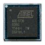
Atmel Embedded Debugger (EDBG)
The Arduino Zero also comes with an Atmel Embedded Debugger (EDBG [5]). That provides a debug interface to the SAMD21 chip and is supported by OpenOCD for bootloader restore or direct programming and debugging. The Atmel EDGB is connected to the debug USB port for programming:
USB device idVendor=03eb, idProduct=2157, bcdDevice= 1.01
USB device strings: Mfr=1, Product=2, SerialNumber=3
Product: EDBG CMSIS-DAP
Manufacturer: Atmel Corp.
SerialNumber: E8VRDGVEYNKJTF8LS45K

Arduino Zero, Atmel EDBG, and Atmel Studio 7
The Arduino Zero was designed in partnership with Atmel (now Microchip) which dedicated to this board a special USB PID with the major purpose to make the board recognizable and differentiate it form other evaluation boards in Atmel Studio. The EDBG chip is used on several Atmel evaluation boards and programmers, you can find the list here [4]. You should consider the Arduino Zero dedicated USB PID (
0x2157) as another USB PID to add to that list. During the manufacturing process Arduino upgrade the EDBG firmware and customize the USB descriptor fields.—https://github.com/arduino/ArduinoCore-samd/issues/286#issuecomment-354807646
Upgrading the firmware with a new one provided by Atmel Studio 7 using
the atfw.exe tool will erase all the factory “Arduino Zero”
USB configurations and will set the USB PID to 0x2111. But
consider that you couldn’t revert the Arduino USB descriptor settings!
Flashing
Build the Zephyr kernel and the Hello World sample application:
west build -b arduino_zero -p -d build/arduino_zero zephyr/samples/hello_world
Connect the Arduino Zero to your host computer using the native USB port (before the USB debug port) to rech the bootloader.
Connect the Arduino Zero to your host computer using the USB debug port (after the native USB port) to reach the virtual console of EDBG.
Run your favorite terminal program to listen for output. Under Linux the terminal should be
/dev/ttyACM0. For example:$ minicom -D /dev/ttyACM0 -o
The -o option tells minicom not to send the modem initialization string. Connection should be configured as follows:
Speed: 115200
Data: 8 bits
Parity: None
Stop bits: 1
Pressing the RST button twice quickly to enter bootloader mode.
Flash the image:
west flash -d build/arduino_zero
You should see “Hello World! arduino_zero” in your terminal.
Debugging
Debugging is only possible over SWD with the help of EDBG!
Do the for the debug session necessary steps as before except enter the bootloader mode and the flashing.
Flash the image and attach a debugger to your board:
west build -b arduino_zero -p -d build/arduino_zero zephyr/samples/hello_world -- -DBOARD_FLASH_RUNNER=openocd
west debug -d build/arduino_zero
You should ends up in a debug console (e.g. a GDB session).
More Samples
LED Blinky
west build -b arduino_zero -p -d build/arduino_zero zephyr/samples/basic/blinky
west flash -d build/arduino_zero
LED Fade
west build -b arduino_zero -p -d build/arduino_zero zephyr/samples/basic/fade_led
west flash -d build/arduino_zero
Basic Threads
west build -b arduino_zero -p -d build/arduino_zero zephyr/samples/basic/threads
west flash -d build/arduino_zero
Hello Shell with USB-CDC/ACM Console
west build -b arduino_zero -p -S usb-console -d build/arduino_zero bridle/samples/helloshell
west flash -d build/arduino_zero
Simple test execution on target
(text in bold is a command input)
uart:~$ hello -h
hello - say hello
uart:~$ hello
Hello from shell.

uart:~$ hwinfo devid
Length: 16
ID: 0xde73d01ae52511ed9cf503ee1d54a301

uart:~$ kernel version
Zephyr version 3.7.0

uart:~$ bridle version
Bridle version 3.7.0

uart:~$ bridle version long
Bridle version 3.7.0.0

uart:~$ bridle info
Zephyr: 3.7.0
Bridle: 3.7.0

uart:~$ device list
devices:
- eic@40001800 (READY)
  DT node labels: eic
- gpio@41004480 (READY)
  DT node labels: portb
- gpio@41004400 (READY)
  DT node labels: porta
- snippet_cdc_acm_console_uart (READY)
  DT node labels: snippet_cdc_acm_console_uart
- sercom@42001c00 (READY)
  DT node labels: sercom5
- sercom@42000800 (READY)
  DT node labels: sercom0 arduino_serial
- adc@42004000 (READY)
  DT node labels: adc
- dac@42004800 (READY)
  DT node labels: dac0
- nvmctrl@41004000 (READY)
  DT node labels: nvmctrl
- sercom@42001400 (READY)
  DT node labels: sercom3 arduino_i2c
- tcc@42002800 (READY)
  DT node labels: tcc2
- leds (READY)

uart:~$ history
[  0] history
[  1] device list
[  2] bridle info
[  3] bridle version long
[  4] bridle version
[  5] kernel version
[  6] hwinfo devid
[  7] hello
[  8] hello -h
Operate with the yellow Rx user LED:
uart:~$ gpio get gpio@41004480 3
0

uart:~$ gpio conf gpio@41004480 3 ol0

uart:~$ gpio set gpio@41004480 3 1
uart:~$ gpio set gpio@41004480 3 0

uart:~$ gpio blink gpio@41004480 3
Hit any key to exit
Operate with the builtin user LED:
uart:~$ pwm usec tcc@42002800 1 20000 20000
uart:~$ pwm usec tcc@42002800 1 20000 19000
uart:~$ pwm usec tcc@42002800 1 20000 18000
uart:~$ pwm usec tcc@42002800 1 20000 17000
uart:~$ pwm usec tcc@42002800 1 20000 16000
uart:~$ pwm usec tcc@42002800 1 20000 15000
uart:~$ pwm usec tcc@42002800 1 20000 10000
uart:~$ pwm usec tcc@42002800 1 20000 5000
uart:~$ pwm usec tcc@42002800 1 20000 2500
uart:~$ pwm usec tcc@42002800 1 20000 500
uart:~$ pwm usec tcc@42002800 1 20000 0
Operate with the loop-back wire from A0 (DAC CH0 VOUT) to A1 (ADC CH2 AIN):
uart:~$ dac setup dac@42004800 0 10
uart:~$ adc adc@42004000 resolution 12
uart:~$ adc adc@42004000 acq_time 10 us
uart:~$ adc adc@42004000 channel positive 2

uart:~$ dac write_value dac@42004800 0 512
uart:~$ adc adc@42004000 read 2
read: 2016

uart:~$ dac write_value dac@42004800 0 1023
uart:~$ adc adc@42004000 read 2
read: 4047
uart:~$ flash read nvmctrl@41004000 13310 40
00013310: 61 72 64 75 69 6e 6f 5f  7a 65 72 6f 00 48 65 6c |arduino_ zero.Hel|
00013320: 6c 6f 20 57 6f 72 6c 64  21 20 49 27 6d 20 54 48 |lo World ! I'm TH|
00013330: 45 20 53 48 45 4c 4c 20  66 72 6f 6d 20 25 73 0a |E SHELL  from %s.|
00013340: 00 28 75 6e 73 69 67 6e  65 64 29 20 63 68 61 72 |.(unsign ed) char|

uart:~$ flash read nvmctrl@41004000 3c000 40
0003C000: ff ff ff ff ff ff ff ff  ff ff ff ff ff ff ff ff |........ ........|
0003C010: ff ff ff ff ff ff ff ff  ff ff ff ff ff ff ff ff |........ ........|
0003C020: ff ff ff ff ff ff ff ff  ff ff ff ff ff ff ff ff |........ ........|
0003C030: ff ff ff ff ff ff ff ff  ff ff ff ff ff ff ff ff |........ ........|

uart:~$ flash test nvmctrl@41004000 3c000 400 2
Erase OK.
Write OK.
Verified OK.
Erase OK.
Write OK.
Verified OK.
Erase-Write-Verify test done.

uart:~$ flash read nvmctrl@41004000 3c000 40
0003C000: 00 01 02 03 04 05 06 07  08 09 0a 0b 0c 0d 0e 0f |........ ........|
0003C010: 10 11 12 13 14 15 16 17  18 19 1a 1b 1c 1d 1e 1f |........ ........|
0003C020: 20 21 22 23 24 25 26 27  28 29 2a 2b 2c 2d 2e 2f | !"#$%&' ()*+,-./|
0003C030: 30 31 32 33 34 35 36 37  38 39 3a 3b 3c 3d 3e 3f |01234567 89:;<=>?|

uart:~$ flash page_info 3c000
Page for address 0x3c000:
start offset: 0x3c000
size: 256
index: 960

uart:~$ flash erase nvmctrl@41004000 3c000 400
Erase success.

uart:~$ flash read nvmctrl@41004000 3c000 40
0003C000: ff ff ff ff ff ff ff ff  ff ff ff ff ff ff ff ff |........ ........|
0003C010: ff ff ff ff ff ff ff ff  ff ff ff ff ff ff ff ff |........ ........|
0003C020: ff ff ff ff ff ff ff ff  ff ff ff ff ff ff ff ff |........ ........|
0003C030: ff ff ff ff ff ff ff ff  ff ff ff ff ff ff ff ff |........ ........|
The Arduino Zero has no on-board I2C devices. For this example the Grove Temperature and Barometer Sensor – BMP280 [19] was connected.
uart:~$ log enable none i2c_sam0

uart:~$ i2c scan sercom@42001400
     0  1  2  3  4  5  6  7  8  9  a  b  c  d  e  f
00:             -- -- -- -- -- -- -- -- -- -- -- --
10: -- -- -- -- -- -- -- -- -- -- -- -- -- -- -- --
20: -- -- -- -- -- -- -- -- 28 -- -- -- -- -- -- --
30: -- -- -- -- -- -- -- -- -- -- -- -- -- -- -- --
40: -- -- -- -- -- -- -- -- -- -- -- -- -- -- -- --
50: -- -- -- -- -- -- -- -- -- -- -- -- -- -- -- --
60: -- -- -- -- -- -- -- -- -- -- -- -- -- -- -- --
70: -- -- -- -- -- -- -- 77
2 devices found on sercom@42001400

uart:~$ log enable inf i2c_sam0
The I2C address 0x77 is a Bosch BMP280 Air Pressure Sensor and their
Chip-ID can read from register 0xd0. The Chip-ID must be 0x58:
uart:~$ i2c read_byte sercom@42001400 77 d0
Output: 0x58
Hint
The I2C address 0x28 is the Data Gateway Interface (DGI [3])
to the builtin Atmel EDBG [5]. See the old ASF3 [2] example code on
GitHub, SAM EDBG TWI Information Interface Example [6], to learn
how to work with this I2C device:
The DGI consists of several physical data interfaces to communicate with the host computer; I2C is only one of them. Communication over the interfaces is bidirectional. It can be used to send events and values from the ATSAMD21G18A, or as a generic printf-style data channel. Traffic over the interfaces can be timestamped on the EDBG for a more accurate tracing of events. Note that timestamping imposes an overhead that reduces maximal throughput. The DGI uses a proprietary protocol, and is thus only compatible with Atmel Studio.