Waveshare LCD Modules
Overview
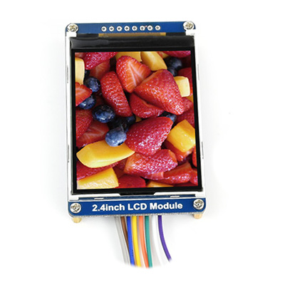
The Waveshare LCD modules are available in different sizes and resolutions. Nearly all displays comes with a special LCD controller wired over SPI up to the board by free wiring.
Supported Modules
Hardware
Features and Resources |
Printed Circuit Board |
3V3/~25㎃ or 5V/~15㎃ LCD 3 1 1
Design Data |
|
Positions
|
|---|
Outputs:
Connections:
|
Data Sheets
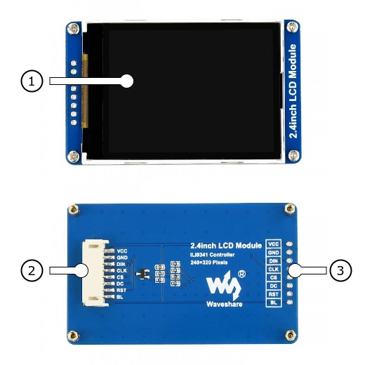
Pinouts
Pin Mapping |
Pinout |
Default Zephyr Peripheral Mapping
Devicetree compatible |
|
Requirements
This shields can be used with any board which provides a configuration either for Arduino or Arduino Nano connectors or for a special connector set and defines node aliases for SPI and GPIO interfaces (see Shields for more details).
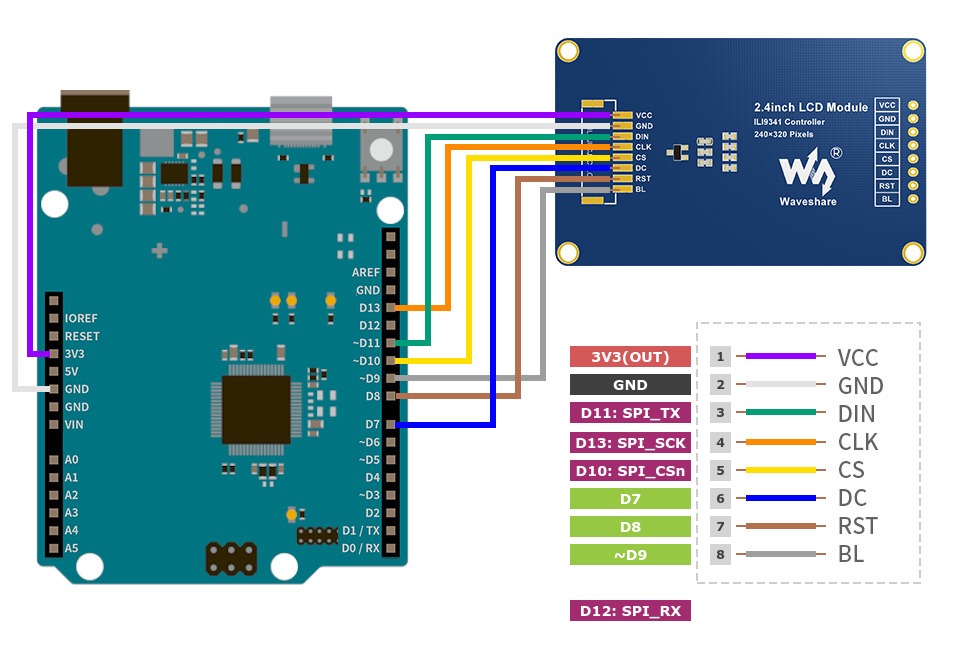
Pin Assignments
Arduino Connector Pin |
Shield Function (LCD Module) |
|---|---|
D9 |
LCD Backlight Enable |
D8 |
ILI9341 Reset |
D7 |
ILI9341 DC (Data/Command) |
D10 |
ILI9341 SPI CSn |
D11 |
SPI COPI (Serial Data Input) |
D12 |
SPI CIPO (Serial Data Out) |
D13 |
SPI SCK (Serial Clock Input) |
The Grove System [5] requires special Devicetree setup for free wiring.
Cytron Maker Pi RP2040
Grove Data Line |
Shield Function (LCD Module) |
|---|---|
D7 |
LCD Backlight Enable |
D28 (ADC2 as GPIO) |
ILI9341 Reset |
D6 |
ILI9341 DC (Data/Command) |
D5 |
ILI9341 SPI CSn |
D3 |
SPI MOSI (Serial Data Input) |
D4 |
SPI MISO (Serial Data Out) |
D2 |
SPI SCK (Serial Clock Input) |
Utilization
This shields can be used with any development board, shield, or snippet that
provides a Devicetree node with either the arduino-nano-header-r3
or the seeed,grove-laced-if property for the compatibility.
In particular, the &arduino_nano_spi or &grove_spi
bus and some GPIO signals of &arduino_nano_header or
&grove_gpio must be free for communication with the LCD on the
modules. On Devicetree level, the shields also providing the special node label
&board_spi_lcd for this purpose.
Programming
Using the Display driver API with chosen display. That is:
chosen { zephyr,display = &lcd_panel; };lcd_panel: &ili9341_240x320 {};If the shield is connected to a board which has Arduino Nano
connector, set -DSHIELD=waveshare_2_4_lcd when you
invoke west build. For example:
Using west:
west build -b cytron_maker_nano_rp2040 -p -S usb-console --shield waveshare_2_4_lcd -d build/waveshare_2_4_lcd-display_test zephyr/samples/drivers/display
west flash -r uf2 -d build/waveshare_2_4_lcd-display_test
Using CMake and ninja:
# Use cmake to configure a Ninja-based buildsystem:
cmake -Bbuild/waveshare_2_4_lcd-display_test -GNinja -DBOARD=cytron_maker_nano_rp2040 -DSHIELD="waveshare_2_4_lcd" zephyr/samples/drivers/display

# Now run the build tool on the generated build system:
ninja -Cbuild/waveshare_2_4_lcd-display_test flash
If the shield is connected to a board which has
Grove System [5] compatiple connectors, set
-DSHIELD=waveshare_2_4_lcd when you invoke
west build and use one of supported boards with
special Devicetree setup for free wiring. For example:
Using west:
west build -b cytron_maker_pi_rp2040 -p -S usb-console --shield waveshare_2_4_lcd -d build/waveshare_2_4_lcd-display_test zephyr/samples/drivers/display
west flash -r uf2 -d build/waveshare_2_4_lcd-display_test
Using CMake and ninja:
# Use cmake to configure a Ninja-based buildsystem:
cmake -Bbuild/waveshare_2_4_lcd-display_test -GNinja -DBOARD=cytron_maker_pi_rp2040 -DSHIELD="waveshare_2_4_lcd" zephyr/samples/drivers/display

# Now run the build tool on the generated build system:
ninja -Cbuild/waveshare_2_4_lcd-display_test flash

|
|---|
TOP LEFT, TOP RIGHT, BOTTOM RIGHT |
Using the LVGL module on top of the Display driver API with chosen display. That is:
chosen { zephyr,display = &lcd_panel; };lcd_panel: &ili9341_240x320 {};If the shield is connected to a board which has Arduino Nano
connector, set -DSHIELD=waveshare_2_4_lcd when you
invoke west build. For example:
Using west:
west build -b cytron_maker_nano_rp2040 -p -S usb-console --shield waveshare_2_4_lcd -d build/waveshare_2_4_lcd-lvgl_basic zephyr/samples/subsys/display/lvgl
west flash -r uf2 -d build/waveshare_2_4_lcd-lvgl_basic
Using CMake and ninja:
# Use cmake to configure a Ninja-based buildsystem:
cmake -Bbuild/waveshare_2_4_lcd-lvgl_basic -GNinja -DBOARD=cytron_maker_nano_rp2040 -DSHIELD="waveshare_2_4_lcd" zephyr/samples/subsys/display/lvgl

# Now run the build tool on the generated build system:
ninja -Cbuild/waveshare_2_4_lcd-lvgl_basic flash
If the shield is connected to a board which has
Grove System [5] compatiple connectors, set
-DSHIELD=waveshare_2_4_lcd when you invoke
west build and use one of supported boards with
special Devicetree setup for free wiring. For example:
Using west:
west build -b cytron_maker_pi_rp2040 -p -S usb-console --shield waveshare_2_4_lcd -d build/waveshare_2_4_lcd-lvgl_basic zephyr/samples/subsys/display/lvgl
west flash -r uf2 -d build/waveshare_2_4_lcd-lvgl_basic
Using CMake and ninja:
# Use cmake to configure a Ninja-based buildsystem:
cmake -Bbuild/waveshare_2_4_lcd-lvgl_basic -GNinja -DBOARD=cytron_maker_pi_rp2040 -DSHIELD="waveshare_2_4_lcd" zephyr/samples/subsys/display/lvgl

# Now run the build tool on the generated build system:
ninja -Cbuild/waveshare_2_4_lcd-lvgl_basic flash