INFINEON PSoC6 WiFi-BT Pioneer Kit
Overview
The PSoC 6 WiFi-BT Pioneer Kit (CY8CKIT-062-WiFi-BT) is a low-cost hardware platform that enables design and debug of the PSoC 62 MCU and the Murata LBEE5KL1DX Module (CYW4343W WiFi + Bluetooth Combo Chip).
The PSoC 6 WiFi-BT Pioneer Kit features the PSoC 62 MCU: a dual-core MCU, with a 150-MHz Arm Cortex-M4 as the primary application processor and a 100-MHz Arm Cortex-M0+ that supports low-power operations, 1MB of Flash, 288KB of SRAM, 104 GPIO, 7 programmable analog blocks, 56 programmable digital blocks, Full-Speed USB, a serial memory interface, a PDM-PCM digital microphone interface, and industry-leading capacitive-sensing with CapSense.
The PSoC 6 WiFi-BT Pioneer board offers compatibility with Arduino shields.
The Cortex-M0+ is a primary core on the board’s SoC. It starts first and enables the CM4 core.
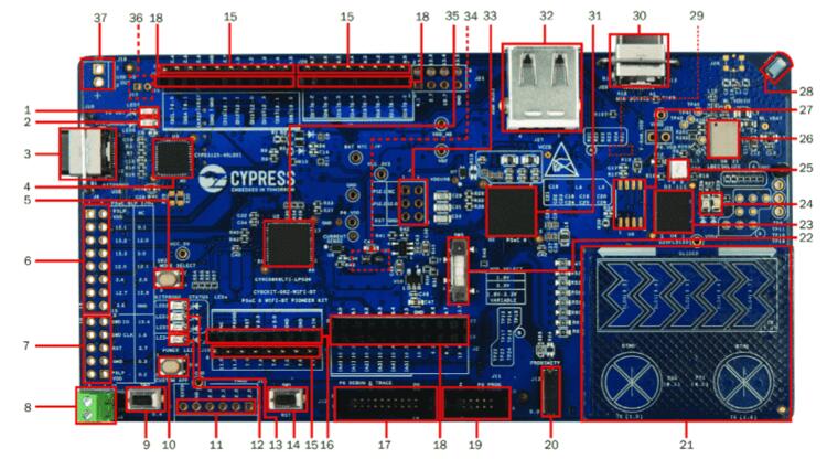
USB PD output voltage availability indicator (LED7)
Battery charging indicator (LED6)
KitProg2 USB Type-C connector (J10)
Cypress EZ-PD™ CCG3 Type-C Port Controller with PD (CYPD3125-40LQXI, U3)
KitProg2 programming mode selection button (SW3)
KitProg2 I/O header (J6)1
KitProg2 programming/custom application header (J7)1
External power supply connector (J9)
PSoC 6 user button (SW2)
KitProg2 application selection button (SW4)
Digilent® Pmod™ compatible I/O header (J14)1
Power LED (LED4)
KitProg2 status LEDs (LED1, LED2, and LED3)
PSoC 6 reset button (SW1)
PSoC 6 I/O header (J18, J19 and J20)
Arduino™ Uno R3 compatible power header (J1)
PSoC 6 debug and trace header (J12)
Arduino Uno R3 compatible PSoC 6 I/O header (J2, J3 and J4)
PSoC 6 program and debug header (J11)
CapSense proximity header (J13)
CapSense slider and buttons
PSoC 6 VDD selection switch (SW5)
Cypress 512-Mbit serial NOR Flash memory (S25-FL512S, U4)
PSoC 6 user LEDs (LED8 and LED9)
RGB LED (LED5)
WiFi/BT module (LBEE5KL 1DX, U6)
Cypress serial Ferroelectric RAM (U5)1
WiFi-BT Antenna
VBACKUP and PMIC control selection switch (SW7)2
PSoC 6 USB device Type-C connector (J28)
Cypress PSoC 6 (CY8C6247BZI-D54, U1)
PSoC 6 USB Host Type-A connector (J27)
Arduino Uno R3 compatible ICSP header (J5)1
PSoC 6 power monitoring jumper (J8)2
KitProg2 (PSoC 5LP) programmer and debugger(CY8C5868LTI-LP039, U2)
Battery connector (J15)1,2
USB PD output voltage (9V/12V) connector (J16)
Hardware
For more information about the PSoC 62 MCU SoC and CY8CKIT-062-WiFi-BT board:
Supported Features
The board configuration supports the following hardware features:
Interface |
Controller |
Driver/Component |
|---|---|---|
NVIC |
on-chip |
nested vectored interrupt controller |
SYSTICK |
on-chip |
system clock |
PINCTRL |
on-chip |
pin control |
UART |
on-chip |
serial port-polling; serial port-interrupt |
The default configuration can be found in the Kconfig boards/cypress/cy8ckit_062_wifi_bt/cy8ckit_062_wifi_bt_cy8c6247_m0_defconfig.
System Clock
The PSoC 62 MCU SoC is configured to use the internal IMO+FLL as a source for the system clock. CM0+ works at 50MHz, CM4 - at 100MHz. Other sources for the system clock are provided in the SOC, depending on your system requirements.
Serial Port
The PSoC 62 MCU SoC has 9 SCB blocks 8 of each can be configured as UART interfaces for serial communication. At the moment UART5 on SCB5 and UART6 on SCB6 are configured. SCB5 is connected to the onboard KitProg2’s USB-UART Bridge, SCB6 to P12_0, P12_1 pins on the J3 of the Arduino Uno R3 compatible PSoC6 I/O header.
OpenOCD Installation
To get the OpenOCD package, it is required that you
Download the software ModusToolbox 3.1. https://softwaretools.infineon.com/tools/com.ifx.tb.tool.modustoolbox
Once downloaded add the path to access the Scripts folder provided by ModusToolbox export PATH=$PATH:/path/to/ModusToolbox/tools_3.1/openocd/scripts
Add the OpenOCD executable file’s path to west flash/debug.
Flash using: west flash –openocd path/to/infineon/openocd/bin/openocd
Debug using: west debug –openocd path/to/infineon/openocd/bin/openocd
Programming and Debugging
The CY8CKIT-062-WiFi-BT includes an onboard programmer/debugger (KitProg2) with mass storage programming to provide debugging, flash programming, and serial communication over USB. There are also PSoC 6 program and debug headers J11 and J12 that can be used with Segger J-Link. A watchdog timer is enabled by default. To disable it call Cy_WDT_Unlock() and Cy_WDT_Disable().
Only the CM0+ core starts by default after the MCU reset. In order to have CM4 core working FW for both cores should be written into Flash. CM0+ FW should starts the CM4 core at one point using Cy_SysEnableCM4(CM4_START_ADDRESS); call. CM4_START_ADDRESS is 0x10060000 in the current configuration. The CM0+/CM4 Flash/SRAM areas are defined in dts/arm/cypress/psoc6.dtsi.
Build the project for CM0+
west build -b cy8ckit_062_wifi_bt/cy8c6247/m0
Switch the DevKit into CMSIS-DAP mode using SW3 (LED2 should blink) and flash the board:
$<openocd_path>\bin\openocd -c "source [find interface/cmsis-dap.cfg]" \
   -c "transport select swd" -c "source [find target/psoc6.cfg]" \
   -c "if [catch {program {<zephyr_path>\samples\hello_world\build\zephyr\zephyr.elf}} ] \
      { echo {** Program operation failed **} } \
      else { echo {** Program operation completed successfully **} }" \
   -c "reset_config srst_only;reset run;psoc6.dap dpreg 0x04 0x00;shutdown"
Switch the DevKit back using SW3. Open a serial terminal (minicom, putty, etc.) and connect to the board with the following settings:
Speed: 115200
Data: 8 bits
Parity: None
Stop bits: 1
Reset the board and the following message will appear on the corresponding serial port:
***** Booting Zephyr OS zephyr-v1.13.0-1877-g9d14874db1 *****
Hello World! cy8ckit_062_wifi_bt