Raspberry Pi Pico TEST Shields
This simple shields are well suited for teaching and training to learn how to access GPIO, PWM or ADC signals and how to use the associated Zephyr APIs. As a demo board you can test if all pins of the Pico are in good condition. As an expansion board, this module contains LEDs, buttons, and a basic ADC function to get you started. It is a simple expansion board for Raspberry Pi Pico beginners.
Supported Shields
Hardware
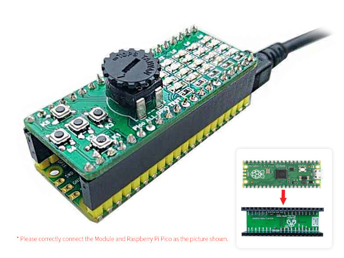
The Spotpear Pico ALL GPIO TEST [1] shield is one of the simplest boards for testing all I/O signal lines of a Raspberry Pi Pico by GPIO or PWM functions. There is also one additional ADC channel for testing purposes directly connected to a simple high-resistance potentiometer.
Features and Resources |
Printed Circuit Board |
3.3V/100㎃ UP DOWN LEFT RIGHT ENTER 20 RED 25 16 1
Design Data |
|
Positions
|
|---|
Inputs:
Outputs:
|
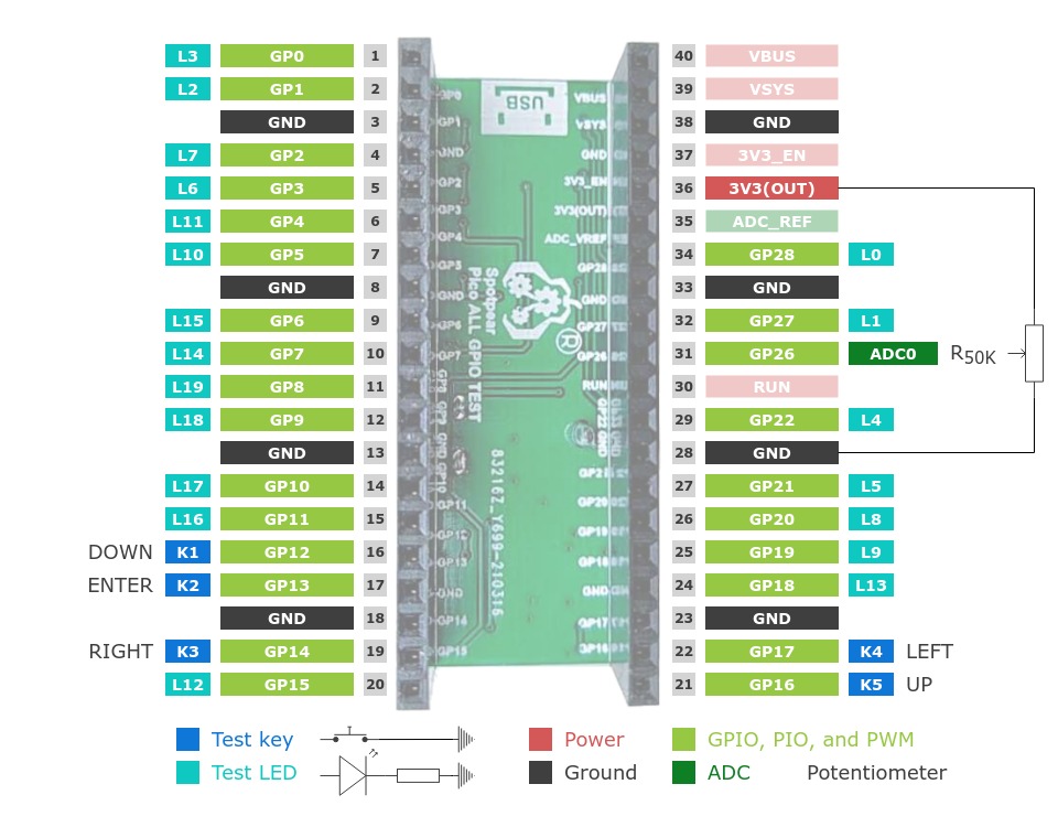
Pinouts
Pin Mapping |
Pinout |
Default Zephyr Peripheral Mapping
Devicetree compatible
|
|
Utilization
This shields can only be used with a development board, shield, or snippet that
provides a configuration for the serial console over USB device, because the
default serial device node &rpipico_serial (a.k.a.
&pico_serial) will be disable completely and can’t be used anymore
for serial communication such as logging or shell access. The same applies also
to the other buses such as I2C or SPI.
Programming
Use the USB Console Snippet (usb-console) and set -DSHIELD=spotpear_pico_test
when you invoke west build. For example:
Using west:
west build -b rpi_pico -p -S usb-console --shield "spotpear_pico_test" -d build/spotpear_pico_test-helloshell bridle/samples/helloshell
west flash -r uf2 -d build/spotpear_pico_test-helloshell
Using CMake and ninja:
# Use cmake to configure a Ninja-based buildsystem:
cmake -Bbuild/spotpear_pico_test-helloshell -GNinja -DBOARD=rpi_pico -DSHIELD=""spotpear_pico_test"" bridle/samples/helloshell

# Now run the build tool on the generated build system:
ninja -Cbuild/spotpear_pico_test-helloshell flash
Simple test execution on target
(text in bold is a command input)
uart:~$ hello -h
hello - say hello
uart:~$ hello
Hello from shell.

uart:~$ hwinfo devid
Length: 8
ID: 0x8c998be1de969148

uart:~$ kernel version
Zephyr version 3.7.2

uart:~$ bridle version
Bridle version 3.7.2

uart:~$ bridle version long
Bridle version 3.7.2.0

uart:~$ bridle info
Zephyr: 3.7.2
Bridle: 3.7.2-dev

uart:~$ device list
devices:
- clock-controller@40008000 (READY)
  DT node labels: clocks
- reset-controller@4000c000 (READY)
  DT node labels: reset
- snippet_cdc_acm_console_uart (READY)
  DT node labels: snippet_cdc_acm_console_uart
- timer@40054000 (READY)
  DT node labels: timer
- gpio@40014000 (READY)
  DT node labels: gpio0
- adc@4004c000 (READY)
  DT node labels: adc
- flash-controller@18000000 (READY)
  DT node labels: ssi
- pwm@40050000 (READY)
  DT node labels: pwm
- vreg@40064000 (READY)
  DT node labels: vreg
- rtc@4005c000 (READY)
  DT node labels: rtc
- pwm_leds (READY)
  DT node labels: pwm_leds

uart:~$ history
[  0] history
[  1] device list
[  2] bridle info
[  3] bridle version long
[  4] bridle version
[  5] kernel version
[  6] hwinfo devid
[  7] hello
[  8] hello -h
Note
PWM LED conflicts with GPIO!
Operations with the test LEDs in PWM mode will fail when ever the corresponding GPIO line was configured as digital output. This condition is irreversible at runtime within the shell and requires a system reset.
Operate with the test LED L0 at PWM12:
uart:~$ led on pwm_leds 0
pwm_leds: turning on LED 0

uart:~$ led set_brightness pwm_leds 0 10
pwm_leds: setting LED 0 brightness to 10

uart:~$ led set_brightness pwm_leds 0 50
pwm_leds: setting LED 0 brightness to 50

uart:~$ led set_brightness pwm_leds 0 100
pwm_leds: setting LED 0 brightness to 100

uart:~$ led off pwm_leds 0
pwm_leds: turning off LED 0
Note
PWM conflicts with GPIO!
Operations with the test LEDs in PWM mode will fail when ever the corresponding GPIO line was configured as digital output. This condition is irreversible at runtime within the shell and requires a system reset.
Operate with the test LED L3 at PWM0:
uart:~$ pwm usec pwm@40050000 0 20000 20000
uart:~$ pwm usec pwm@40050000 0 20000 19000
uart:~$ pwm usec pwm@40050000 0 20000 18000
uart:~$ pwm usec pwm@40050000 0 20000 17000
uart:~$ pwm usec pwm@40050000 0 20000 16000
uart:~$ pwm usec pwm@40050000 0 20000 15000
uart:~$ pwm usec pwm@40050000 0 20000 10000
uart:~$ pwm usec pwm@40050000 0 20000 5000
uart:~$ pwm usec pwm@40050000 0 20000 2500
uart:~$ pwm usec pwm@40050000 0 20000 500
uart:~$ pwm usec pwm@40050000 0 20000 0
Operate with the test LED L5 at GP21:
uart:~$ gpio get gpio@40014000 21
0

uart:~$ gpio conf gpio@40014000 21 oh0
uart:~$ gpio set gpio@40014000 21 1
uart:~$ gpio set gpio@40014000 21 0

uart:~$ gpio blink gpio@40014000 21
Hit any key to exit
Operate with the ENTER test key K2 at GP13:
uart:~$ gpio get gpio@40014000 13
0

uart:~$ gpio conf gpio@40014000 13 iul
uart:~$ gpio get gpio@40014000 13
0
uart:~$ gpio get gpio@40014000 13
1
uart:~$ gpio get gpio@40014000 13
0
Operate with the on-shield potentiometer Rₚ on ADC_CH0:
uart:~$ adc adc@4004c000 resolution 12
uart:~$ adc adc@4004c000 channel id 0

uart:~$ adc adc@4004c000 read 0
read: 13

uart:~$ adc adc@4004c000 read 0
read: 1896

uart:~$ adc adc@4004c000 read 0
read: 4095
Using west:
west build -b rpi_pico/rp2040/w -p -S usb-console --shield "spotpear_pico_test" -d build/spotpear_pico_test-helloshell bridle/samples/helloshell
west flash -r uf2 -d build/spotpear_pico_test-helloshell
Using CMake and ninja:
# Use cmake to configure a Ninja-based buildsystem:
cmake -Bbuild/spotpear_pico_test-helloshell -GNinja -DBOARD=rpi_pico/rp2040/w -DSHIELD=""spotpear_pico_test"" bridle/samples/helloshell

# Now run the build tool on the generated build system:
ninja -Cbuild/spotpear_pico_test-helloshell flash
Simple test execution on target
(text in bold is a command input)
uart:~$ hello -h
hello - say hello
uart:~$ hello
Hello from shell.

uart:~$ hwinfo devid
Length: 8
ID: 0x8c998be1de969148

uart:~$ kernel version
Zephyr version 3.7.2

uart:~$ bridle version
Bridle version 3.7.2

uart:~$ bridle version long
Bridle version 3.7.2.0

uart:~$ bridle info
Zephyr: 3.7.2
Bridle: 3.7.2-dev

uart:~$ device list
devices:
- clock-controller@40008000 (READY)
  DT node labels: clocks
- reset-controller@4000c000 (READY)
  DT node labels: reset
- snippet_cdc_acm_console_uart (READY)
  DT node labels: snippet_cdc_acm_console_uart
- timer@40054000 (READY)
  DT node labels: timer
- gpio@40014000 (READY)
  DT node labels: gpio0
- adc@4004c000 (READY)
  DT node labels: adc
- flash-controller@18000000 (READY)
  DT node labels: ssi
- pwm@40050000 (READY)
  DT node labels: pwm
- vreg@40064000 (READY)
  DT node labels: vreg
- rtc@4005c000 (READY)
  DT node labels: rtc
- pwm_leds (READY)
  DT node labels: pwm_leds

uart:~$ history
[  0] history
[  1] device list
[  2] bridle info
[  3] bridle version long
[  4] bridle version
[  5] kernel version
[  6] hwinfo devid
[  7] hello
[  8] hello -h
Note
PWM LED conflicts with GPIO!
Operations with the test LEDs in PWM mode will fail when ever the corresponding GPIO line was configured as digital output. This condition is irreversible at runtime within the shell and requires a system reset.
Operate with the test LED L0 at PWM12:
uart:~$ led on pwm_leds 0
pwm_leds: turning on LED 0

uart:~$ led set_brightness pwm_leds 0 10
pwm_leds: setting LED 0 brightness to 10

uart:~$ led set_brightness pwm_leds 0 50
pwm_leds: setting LED 0 brightness to 50

uart:~$ led set_brightness pwm_leds 0 100
pwm_leds: setting LED 0 brightness to 100

uart:~$ led off pwm_leds 0
pwm_leds: turning off LED 0
Note
PWM conflicts with GPIO!
Operations with the test LEDs in PWM mode will fail when ever the corresponding GPIO line was configured as digital output. This condition is irreversible at runtime within the shell and requires a system reset.
Operate with the test LED L3 at PWM0:
uart:~$ pwm usec pwm@40050000 0 20000 20000
uart:~$ pwm usec pwm@40050000 0 20000 19000
uart:~$ pwm usec pwm@40050000 0 20000 18000
uart:~$ pwm usec pwm@40050000 0 20000 17000
uart:~$ pwm usec pwm@40050000 0 20000 16000
uart:~$ pwm usec pwm@40050000 0 20000 15000
uart:~$ pwm usec pwm@40050000 0 20000 10000
uart:~$ pwm usec pwm@40050000 0 20000 5000
uart:~$ pwm usec pwm@40050000 0 20000 2500
uart:~$ pwm usec pwm@40050000 0 20000 500
uart:~$ pwm usec pwm@40050000 0 20000 0
Operate with the test LED L5 at GP21:
uart:~$ gpio get gpio@40014000 21
0

uart:~$ gpio conf gpio@40014000 21 oh0
uart:~$ gpio set gpio@40014000 21 1
uart:~$ gpio set gpio@40014000 21 0

uart:~$ gpio blink gpio@40014000 21
Hit any key to exit
Operate with the ENTER test key K2 at GP13:
uart:~$ gpio get gpio@40014000 13
0

uart:~$ gpio conf gpio@40014000 13 iul
uart:~$ gpio get gpio@40014000 13
0
uart:~$ gpio get gpio@40014000 13
1
uart:~$ gpio get gpio@40014000 13
0
Operate with the on-shield potentiometer Rₚ on ADC_CH0:
uart:~$ adc adc@4004c000 resolution 12
uart:~$ adc adc@4004c000 channel id 0

uart:~$ adc adc@4004c000 read 0
read: 13

uart:~$ adc adc@4004c000 read 0
read: 1896

uart:~$ adc adc@4004c000 read 0
read: 4095
on standard 4㎆ revision
Using west:
west build -b waveshare_rp2040_plus -p -S usb-console --shield "spotpear_pico_test" -d build/spotpear_pico_test-helloshell bridle/samples/helloshell
west flash -r uf2 -d build/spotpear_pico_test-helloshell
Using CMake and ninja:
# Use cmake to configure a Ninja-based buildsystem:
cmake -Bbuild/spotpear_pico_test-helloshell -GNinja -DBOARD=waveshare_rp2040_plus -DSHIELD=""spotpear_pico_test"" bridle/samples/helloshell

# Now run the build tool on the generated build system:
ninja -Cbuild/spotpear_pico_test-helloshell flash
on extended 16㎆ revision
Using west:
west build -b waveshare_rp2040_plus@16mb -p -S usb-console --shield "spotpear_pico_test" -d build/spotpear_pico_test-helloshell bridle/samples/helloshell
west flash -r uf2 -d build/spotpear_pico_test-helloshell
Using CMake and ninja:
# Use cmake to configure a Ninja-based buildsystem:
cmake -Bbuild/spotpear_pico_test-helloshell -GNinja -DBOARD=waveshare_rp2040_plus@16mb -DSHIELD=""spotpear_pico_test"" bridle/samples/helloshell

# Now run the build tool on the generated build system:
ninja -Cbuild/spotpear_pico_test-helloshell flash
Simple test execution on target
(text in bold is a command input)
uart:~$ hello -h
hello - say hello
uart:~$ hello
Hello from shell.

uart:~$ hwinfo devid
Length: 8
ID: 0x8c998be1de969148

uart:~$ kernel version
Zephyr version 3.7.2

uart:~$ bridle version
Bridle version 3.7.2

uart:~$ bridle version long
Bridle version 3.7.2.0

uart:~$ bridle info
Zephyr: 3.7.2
Bridle: 3.7.2-dev

uart:~$ device list
devices:
- clock-controller@40008000 (READY)
  DT node labels: clocks
- reset-controller@4000c000 (READY)
  DT node labels: reset
- snippet_cdc_acm_console_uart (READY)
  DT node labels: snippet_cdc_acm_console_uart
- timer@40054000 (READY)
  DT node labels: timer
- gpio@40014000 (READY)
  DT node labels: gpio0
- adc@4004c000 (READY)
  DT node labels: adc
- flash-controller@18000000 (READY)
  DT node labels: ssi
- pwm@40050000 (READY)
  DT node labels: pwm
- vreg@40064000 (READY)
  DT node labels: vreg
- rtc@4005c000 (READY)
  DT node labels: rtc
- pwm_leds (READY)
  DT node labels: pwm_leds

uart:~$ history
[  0] history
[  1] device list
[  2] bridle info
[  3] bridle version long
[  4] bridle version
[  5] kernel version
[  6] hwinfo devid
[  7] hello
[  8] hello -h
Note
PWM LED conflicts with GPIO!
Operations with the test LEDs in PWM mode will fail when ever the corresponding GPIO line was configured as digital output. This condition is irreversible at runtime within the shell and requires a system reset.
Operate with the test LED L0 at PWM12:
uart:~$ led on pwm_leds 0
pwm_leds: turning on LED 0

uart:~$ led set_brightness pwm_leds 0 10
pwm_leds: setting LED 0 brightness to 10

uart:~$ led set_brightness pwm_leds 0 50
pwm_leds: setting LED 0 brightness to 50

uart:~$ led set_brightness pwm_leds 0 100
pwm_leds: setting LED 0 brightness to 100

uart:~$ led off pwm_leds 0
pwm_leds: turning off LED 0
Note
PWM conflicts with GPIO!
Operations with the test LEDs in PWM mode will fail when ever the corresponding GPIO line was configured as digital output. This condition is irreversible at runtime within the shell and requires a system reset.
Operate with the test LED L3 at PWM0:
uart:~$ pwm usec pwm@40050000 0 20000 20000
uart:~$ pwm usec pwm@40050000 0 20000 19000
uart:~$ pwm usec pwm@40050000 0 20000 18000
uart:~$ pwm usec pwm@40050000 0 20000 17000
uart:~$ pwm usec pwm@40050000 0 20000 16000
uart:~$ pwm usec pwm@40050000 0 20000 15000
uart:~$ pwm usec pwm@40050000 0 20000 10000
uart:~$ pwm usec pwm@40050000 0 20000 5000
uart:~$ pwm usec pwm@40050000 0 20000 2500
uart:~$ pwm usec pwm@40050000 0 20000 500
uart:~$ pwm usec pwm@40050000 0 20000 0
Operate with the test LED L5 at GP21:
uart:~$ gpio get gpio@40014000 21
0

uart:~$ gpio conf gpio@40014000 21 oh0
uart:~$ gpio set gpio@40014000 21 1
uart:~$ gpio set gpio@40014000 21 0

uart:~$ gpio blink gpio@40014000 21
Hit any key to exit
Operate with the ENTER test key K2 at GP13:
uart:~$ gpio get gpio@40014000 13
0

uart:~$ gpio conf gpio@40014000 13 iul
uart:~$ gpio get gpio@40014000 13
0
uart:~$ gpio get gpio@40014000 13
1
uart:~$ gpio get gpio@40014000 13
0
Operate with the on-shield potentiometer Rₚ on ADC_CH0:
uart:~$ adc adc@4004c000 resolution 12
uart:~$ adc adc@4004c000 channel id 0

uart:~$ adc adc@4004c000 read 0
read: 13

uart:~$ adc adc@4004c000 read 0
read: 1896

uart:~$ adc adc@4004c000 read 0
read: 4095
Using west:
west build -b waveshare_rp2040_lcd_0_96 -p -S usb-console --shield "spotpear_pico_test" -d build/spotpear_pico_test-helloshell bridle/samples/helloshell
west flash -r uf2 -d build/spotpear_pico_test-helloshell
Using CMake and ninja:
# Use cmake to configure a Ninja-based buildsystem:
cmake -Bbuild/spotpear_pico_test-helloshell -GNinja -DBOARD=waveshare_rp2040_lcd_0_96 -DSHIELD=""spotpear_pico_test"" bridle/samples/helloshell

# Now run the build tool on the generated build system:
ninja -Cbuild/spotpear_pico_test-helloshell flash
Simple test execution on target
(text in bold is a command input)
uart:~$ hello -h
hello - say hello
uart:~$ hello
Hello from shell.

uart:~$ hwinfo devid
Length: 8
ID: 0x8c998be1de969148

uart:~$ kernel version
Zephyr version 3.7.2

uart:~$ bridle version
Bridle version 3.7.2

uart:~$ bridle version long
Bridle version 3.7.2.0

uart:~$ bridle info
Zephyr: 3.7.2
Bridle: 3.7.2-dev

uart:~$ device list
devices:
- clock-controller@40008000 (READY)
  DT node labels: clocks
- reset-controller@4000c000 (READY)
  DT node labels: reset
- snippet_cdc_acm_console_uart (READY)
  DT node labels: snippet_cdc_acm_console_uart
- timer@40054000 (READY)
  DT node labels: timer
- gpio@40014000 (READY)
  DT node labels: gpio0
- adc@4004c000 (READY)
  DT node labels: adc
- flash-controller@18000000 (READY)
  DT node labels: ssi
- pwm@40050000 (READY)
  DT node labels: pwm
- vreg@40064000 (READY)
  DT node labels: vreg
- rtc@4005c000 (READY)
  DT node labels: rtc
- pwm_leds (READY)
  DT node labels: pwm_leds

uart:~$ history
[  0] history
[  1] device list
[  2] bridle info
[  3] bridle version long
[  4] bridle version
[  5] kernel version
[  6] hwinfo devid
[  7] hello
[  8] hello -h
Note
PWM LED conflicts with GPIO!
Operations with the test LEDs in PWM mode will fail when ever the corresponding GPIO line was configured as digital output. This condition is irreversible at runtime within the shell and requires a system reset.
Operate with the test LED L0 at PWM12:
uart:~$ led on pwm_leds 0
pwm_leds: turning on LED 0

uart:~$ led set_brightness pwm_leds 0 10
pwm_leds: setting LED 0 brightness to 10

uart:~$ led set_brightness pwm_leds 0 50
pwm_leds: setting LED 0 brightness to 50

uart:~$ led set_brightness pwm_leds 0 100
pwm_leds: setting LED 0 brightness to 100

uart:~$ led off pwm_leds 0
pwm_leds: turning off LED 0
Note
PWM conflicts with GPIO!
Operations with the test LEDs in PWM mode will fail when ever the corresponding GPIO line was configured as digital output. This condition is irreversible at runtime within the shell and requires a system reset.
Operate with the test LED L3 at PWM0:
uart:~$ pwm usec pwm@40050000 0 20000 20000
uart:~$ pwm usec pwm@40050000 0 20000 19000
uart:~$ pwm usec pwm@40050000 0 20000 18000
uart:~$ pwm usec pwm@40050000 0 20000 17000
uart:~$ pwm usec pwm@40050000 0 20000 16000
uart:~$ pwm usec pwm@40050000 0 20000 15000
uart:~$ pwm usec pwm@40050000 0 20000 10000
uart:~$ pwm usec pwm@40050000 0 20000 5000
uart:~$ pwm usec pwm@40050000 0 20000 2500
uart:~$ pwm usec pwm@40050000 0 20000 500
uart:~$ pwm usec pwm@40050000 0 20000 0
Operate with the test LED L5 at GP21:
uart:~$ gpio get gpio@40014000 21
0

uart:~$ gpio conf gpio@40014000 21 oh0
uart:~$ gpio set gpio@40014000 21 1
uart:~$ gpio set gpio@40014000 21 0

uart:~$ gpio blink gpio@40014000 21
Hit any key to exit
Operate with the ENTER test key K2 at GP13:
uart:~$ gpio get gpio@40014000 13
0

uart:~$ gpio conf gpio@40014000 13 iul
uart:~$ gpio get gpio@40014000 13
0
uart:~$ gpio get gpio@40014000 13
1
uart:~$ gpio get gpio@40014000 13
0
Operate with the on-shield potentiometer Rₚ on ADC_CH0:
uart:~$ adc adc@4004c000 resolution 12
uart:~$ adc adc@4004c000 channel id 0

uart:~$ adc adc@4004c000 read 0
read: 13

uart:~$ adc adc@4004c000 read 0
read: 1896

uart:~$ adc adc@4004c000 read 0
read: 4095
More Samples
Input dump
Prints all input events as defined by the shield’s Devicetree. See also Zephyr sample: Input dump.
Print the input events related to the five on-shield test keys using the Input subsystem API. That are:
zephyr,code = <INPUT_KEY_DOWN>;zephyr,code = <INPUT_KEY_ENTER>;zephyr,code = <INPUT_KEY_RIGHT>;zephyr,code = <INPUT_KEY_LEFT>;zephyr,code = <INPUT_KEY_UP>;Devicetree compatible
zephyr,lvgl-keypad-inputwith devicetree relationlvgl_keypad: lvgl-keypad { input = <&gpio_keys>; };K1 :input-codes = <INPUT_KEY_DOWN>;:lvgl-codes = <LV_KEY_DOWN>;K2 :input-codes = <INPUT_KEY_ENTER>;:lvgl-codes = <LV_KEY_ENTER>;K3 :input-codes = <INPUT_KEY_RIGHT>;:lvgl-codes = <LV_KEY_RIGHT>;K4 :input-codes = <INPUT_KEY_LEFT>;:lvgl-codes = <LV_KEY_LEFT>;K5 :input-codes = <INPUT_KEY_UP>;:lvgl-codes = <LV_KEY_UP>;
west build -b rpi_pico -p -S usb-console --shield "spotpear_pico_test" -d build/spotpear_pico_test-input_dump zephyr/samples/subsys/input/input_dump
west flash -r uf2 -d build/spotpear_pico_test-input_dump
west build -b rpi_pico/rp2040/w -p -S usb-console --shield "spotpear_pico_test" -d build/spotpear_pico_test-input_dump zephyr/samples/subsys/input/input_dump
west flash -r uf2 -d build/spotpear_pico_test-input_dump
on standard 4㎆ revision
west build -b waveshare_rp2040_plus -p -S usb-console --shield "spotpear_pico_test" -d build/spotpear_pico_test-input_dump zephyr/samples/subsys/input/input_dump
west flash -r uf2 -d build/spotpear_pico_test-input_dump
on extended 16㎆ revision
west build -b waveshare_rp2040_plus@16mb -p -S usb-console --shield "spotpear_pico_test" -d build/spotpear_pico_test-input_dump zephyr/samples/subsys/input/input_dump
west flash -r uf2 -d build/spotpear_pico_test-input_dump
west build -b waveshare_rp2040_lcd_0_96 -p -S usb-console --shield "spotpear_pico_test" -d build/spotpear_pico_test-input_dump zephyr/samples/subsys/input/input_dump
west flash -r uf2 -d build/spotpear_pico_test-input_dump
Simple test execution on target
***** delaying boot 4000ms (per build configuration) *****
W: BUS RESET
W: BUS RESET
*** Booting Zephyr OS build v3.7.2… (delayed boot 4000ms) ***
Input sample started
I: input event: dev=gpio_keys        SYN type= 1 code=108 value=1
I: input event: dev=gpio_keys        SYN type= 1 code=108 value=0
I: input event: dev=gpio_keys        SYN type= 1 code= 28 value=1
I: input event: dev=gpio_keys        SYN type= 1 code= 28 value=0
I: input event: dev=gpio_keys        SYN type= 1 code=106 value=1
I: input event: dev=gpio_keys        SYN type= 1 code=106 value=0
I: input event: dev=gpio_keys        SYN type= 1 code=105 value=1
I: input event: dev=gpio_keys        SYN type= 1 code=105 value=0
I: input event: dev=gpio_keys        SYN type= 1 code=103 value=1
I: input event: dev=gpio_keys        SYN type= 1 code=103 value=0
Analog-to-Digital Converter (ADC)
Read analog inputs from ADC channels as defined by the shield’s Devicetree. See also Zephyr sample: Analog-to-Digital Converter (ADC) with devicetree.
Read and print the analog input value from the one on-shield high-resistance potentiometer using the ADC driver API. That are:
zephyr,user { io-channels = <&adc 0>; };west build -b rpi_pico -p -S usb-console --shield "spotpear_pico_test" -d build/spotpear_pico_test-drivers_adc zephyr/samples/drivers/adc/adc_dt
west flash -r uf2 -d build/spotpear_pico_test-drivers_adc
west build -b rpi_pico/rp2040/w -p -S usb-console --shield "spotpear_pico_test" -d build/spotpear_pico_test-drivers_adc zephyr/samples/drivers/adc/adc_dt
west flash -r uf2 -d build/spotpear_pico_test-drivers_adc
on standard 4㎆ revision
west build -b waveshare_rp2040_plus -p -S usb-console --shield "spotpear_pico_test" -d build/spotpear_pico_test-drivers_adc zephyr/samples/drivers/adc/adc_dt
west flash -r uf2 -d build/spotpear_pico_test-drivers_adc
on extended 16㎆ revision
west build -b waveshare_rp2040_plus@16mb -p -S usb-console --shield "spotpear_pico_test" -d build/spotpear_pico_test-drivers_adc zephyr/samples/drivers/adc/adc_dt
west flash -r uf2 -d build/spotpear_pico_test-drivers_adc
west build -b waveshare_rp2040_lcd_0_96 -p -S usb-console --shield "spotpear_pico_test" -d build/spotpear_pico_test-drivers_adc zephyr/samples/drivers/adc/adc_dt
west flash -r uf2 -d build/spotpear_pico_test-drivers_adc
Simple test execution on target
***** delaying boot 4000ms (per build configuration) *****
[00:00:00.287,000] <wrn> udc_rpi: BUS RESET
[00:00:00.368,000] <wrn> udc_rpi: BUS RESET
*** Booting Zephyr OS build v3.7.2… (delayed boot 4000ms) ***
ADC reading[0]:
- adc@4004c000, channel 0: 25 = 20 mV
ADC reading[1]:
- adc@4004c000, channel 0: 171 = 137 mV
ADC reading[2]:
- adc@4004c000, channel 0: 979 = 788 mV
ADC reading[3]:
- adc@4004c000, channel 0: 1818 = 1464 mV
ADC reading[4]:
- adc@4004c000, channel 0: 2521 = 2031 mV
ADC reading[5]:
- adc@4004c000, channel 0: 3152 = 2539 mV
ADC reading[6]:
- adc@4004c000, channel 0: 4019 = 3237 mV
ADC reading[7]:
- adc@4004c000, channel 0: 4095 = 3299 mV
Light-Emitting Diode (LED) by PWM
Control PWM LEDs as defined by the shield’s Devicetree. See also Zephyr sample: LED PWM.
For each of the twenty on-shield LEDs attached to the first
pwm-leds device instance found in Devicetree the same
standard test pattern (described in the original sample documentation)
is executed using the LED driver API. That are:
&pwm_leds { pl0: pl0 { pwms = <&pwm 12 /* … */>; }; };&pwm_leds { pl1: pl1 { pwms = <&pwm 11 /* … */>; }; };&pwm_leds { pl2: pl2 { pwms = <&pwm 1 /* … */>; }; };&pwm_leds { pl3: pl3 { pwms = <&pwm 0 /* … */>; }; };&pwm_leds { pl4: pl4 { pwms = <&pwm 6 /* … */>; }; };&pwm_leds { pl5: pl5 { pwms = <&pwm 5 /* … */>; }; };&pwm_leds { pl6: pl6 { pwms = <&pwm 3 /* … */>; }; };&pwm_leds { pl7: pl7 { pwms = <&pwm 2 /* … */>; }; };&pwm_leds { pl8: pl8 { pwms = <&pwm 4 /* … */>; }; };&pwm_leds { pl9: pl9 { pwms = <&pwm 3 /* … */>; }; };&pwm_leds { pl10: pl10 { pwms = <&pwm 5 /* … */>; }; };&pwm_leds { pl11: pl11 { pwms = <&pwm 4 /* … */>; }; };&pwm_leds { pl12: pl12 { pwms = <&pwm 15 /* … */>; }; };&pwm_leds { pl13: pl13 { pwms = <&pwm 2 /* … */>; }; };&pwm_leds { pl14: pl14 { pwms = <&pwm 7 /* … */>; }; };&pwm_leds { pl15: pl15 { pwms = <&pwm 6 /* … */>; }; };&pwm_leds { pl16: pl16 { pwms = <&pwm 11 /* … */>; }; };&pwm_leds { pl17: pl17 { pwms = <&pwm 10 /* … */>; }; };&pwm_leds { pl18: pl18 { pwms = <&pwm 9 /* … */>; }; };&pwm_leds { pl19: pl19 { pwms = <&pwm 8 /* … */>; }; };west build -b rpi_pico -p -S usb-console --shield "spotpear_pico_test" -d build/spotpear_pico_test-drivers_led_pwm zephyr/samples/drivers/led_pwm
west flash -r uf2 -d build/spotpear_pico_test-drivers_led_pwm
west build -b rpi_pico/rp2040/w -p -S usb-console --shield "spotpear_pico_test" -d build/spotpear_pico_test-drivers_led_pwm zephyr/samples/drivers/led_pwm
west flash -r uf2 -d build/spotpear_pico_test-drivers_led_pwm
on standard 4㎆ revision
west build -b waveshare_rp2040_plus -p -S usb-console --shield "spotpear_pico_test" -d build/spotpear_pico_test-drivers_led_pwm zephyr/samples/drivers/led_pwm
west flash -r uf2 -d build/spotpear_pico_test-drivers_led_pwm
on extended 16㎆ revision
west build -b waveshare_rp2040_plus@16mb -p -S usb-console --shield "spotpear_pico_test" -d build/spotpear_pico_test-drivers_led_pwm zephyr/samples/drivers/led_pwm
west flash -r uf2 -d build/spotpear_pico_test-drivers_led_pwm
west build -b waveshare_rp2040_lcd_0_96 -p -S usb-console --shield "spotpear_pico_test" -d build/spotpear_pico_test-drivers_led_pwm zephyr/samples/drivers/led_pwm
west flash -r uf2 -d build/spotpear_pico_test-drivers_led_pwm
Simple test execution on target
***** delaying boot 4000ms (per build configuration) *****
[00:00:00.181,000] <wrn> udc_rpi: BUS RESET
[00:00:00.266,000] <wrn> udc_rpi: BUS RESET
*** Booting Zephyr OS build v3.7.2… (delayed boot 4000ms) ***
[00:00:04.003,000] <inf> main: Testing LED 0 - L0: Test LED 0
[00:00:04.004,000] <inf> main:   Turned on
[00:00:05.005,000] <inf> main:   Turned off
[00:00:06.005,000] <inf> main:   Increasing brightness gradually
[00:00:08.026,000] <err> main: err=-22
[00:00:08.026,000] <inf> main: Testing LED 1 - L1: Test LED 1
[00:00:08.027,000] <inf> main:   Turned on
[00:00:09.027,000] <inf> main:   Turned off
[00:00:10.028,000] <inf> main:   Increasing brightness gradually
[00:00:12.049,000] <err> main: err=-22
[00:00:12.049,000] <inf> main: Testing LED 2 - L2: Test LED 2
[00:00:12.049,000] <inf> main:   Turned on
[00:00:13.050,000] <inf> main:   Turned off
[00:00:14.050,000] <inf> main:   Increasing brightness gradually
[00:00:16.071,000] <err> main: err=-22
[00:00:16.071,000] <inf> main: Testing LED 3 - L3: Test LED 3
[00:00:16.072,000] <inf> main:   Turned on
[00:00:17.072,000] <inf> main:   Turned off
[00:00:18.073,000] <inf> main:   Increasing brightness gradually
[00:00:20.094,000] <err> main: err=-22
[00:00:20.094,000] <inf> main: Testing LED 4 - L4: Test LED 4
[00:00:20.094,000] <inf> main:   Turned on
[00:00:21.095,000] <inf> main:   Turned off
[00:00:22.095,000] <inf> main:   Increasing brightness gradually
[00:00:24.116,000] <err> main: err=-22
[00:00:24.117,000] <inf> main: Testing LED 5 - L5: Test LED 5
[00:00:24.117,000] <inf> main:   Turned on
[00:00:25.118,000] <inf> main:   Turned off
[00:00:26.118,000] <inf> main:   Increasing brightness gradually
[00:00:28.139,000] <err> main: err=-22
[00:00:28.139,000] <inf> main: Testing LED 6 - L6: Test LED 6
[00:00:28.140,000] <inf> main:   Turned on
[00:00:29.140,000] <inf> main:   Turned off
[00:00:30.141,000] <inf> main:   Increasing brightness gradually
[00:00:32.162,000] <err> main: err=-22
[00:00:32.162,000] <inf> main: Testing LED 7 - L7: Test LED 7
[00:00:32.162,000] <inf> main:   Turned on
[00:00:33.163,000] <inf> main:   Turned off
[00:00:34.163,000] <inf> main:   Increasing brightness gradually
[00:00:36.184,000] <err> main: err=-22
[00:00:36.184,000] <inf> main: Testing LED 8 - L8: Test LED 8
[00:00:36.185,000] <inf> main:   Turned on
[00:00:37.185,000] <inf> main:   Turned off
[00:00:38.186,000] <inf> main:   Increasing brightness gradually
[00:00:40.207,000] <err> main: err=-22
[00:00:40.207,000] <inf> main: Testing LED 9 - L9: Test LED 9
[00:00:40.207,000] <inf> main:   Turned on
[00:00:41.208,000] <inf> main:   Turned off
[00:00:42.208,000] <inf> main:   Increasing brightness gradually
[00:00:44.229,000] <err> main: err=-22
[00:00:44.230,000] <inf> main: Testing LED 10 - L10: Test LED 10
[00:00:44.230,000] <inf> main:   Turned on
[00:00:45.231,000] <inf> main:   Turned off
[00:00:46.231,000] <inf> main:   Increasing brightness gradually
[00:00:48.252,000] <err> main: err=-22
[00:00:48.252,000] <inf> main: Testing LED 11 - L11: Test LED 11
[00:00:48.253,000] <inf> main:   Turned on
[00:00:49.253,000] <inf> main:   Turned off
[00:00:50.254,000] <inf> main:   Increasing brightness gradually
[00:00:52.275,000] <err> main: err=-22
[00:00:52.275,000] <inf> main: Testing LED 12 - L12: Test LED 12
[00:00:52.275,000] <inf> main:   Turned on
[00:00:53.276,000] <inf> main:   Turned off
[00:00:54.276,000] <inf> main:   Increasing brightness gradually
[00:00:56.297,000] <err> main: err=-22
[00:00:56.298,000] <inf> main: Testing LED 13 - L13: Test LED 13
[00:00:56.298,000] <inf> main:   Turned on
[00:00:57.298,000] <inf> main:   Turned off
[00:00:58.299,000] <inf> main:   Increasing brightness gradually
[00:01:00.320,000] <err> main: err=-22
[00:01:00.320,000] <inf> main: Testing LED 14 - L14: Test LED 14
[00:01:00.321,000] <inf> main:   Turned on
[00:01:01.321,000] <inf> main:   Turned off
[00:01:02.322,000] <inf> main:   Increasing brightness gradually
[00:01:04.342,000] <err> main: err=-22
[00:01:04.343,000] <inf> main: Testing LED 15 - L15: Test LED 15
[00:01:04.343,000] <inf> main:   Turned on
[00:01:05.344,000] <inf> main:   Turned off
[00:01:06.344,000] <inf> main:   Increasing brightness gradually
[00:01:08.365,000] <err> main: err=-22
[00:01:08.365,000] <inf> main: Testing LED 16 - L16: Test LED 16
[00:01:08.366,000] <inf> main:   Turned on
[00:01:09.366,000] <inf> main:   Turned off
[00:01:10.367,000] <inf> main:   Increasing brightness gradually
[00:01:12.388,000] <err> main: err=-22
[00:01:12.388,000] <inf> main: Testing LED 17 - L17: Test LED 17
[00:01:12.388,000] <inf> main:   Turned on
[00:01:13.389,000] <inf> main:   Turned off
[00:01:14.389,000] <inf> main:   Increasing brightness gradually
[00:01:16.410,000] <err> main: err=-22
[00:01:16.411,000] <inf> main: Testing LED 18 - L18: Test LED 18
[00:01:16.411,000] <inf> main:   Turned on
[00:01:17.412,000] <inf> main:   Turned off
[00:01:18.412,000] <inf> main:   Increasing brightness gradually
[00:01:20.433,000] <err> main: err=-22
[00:01:20.433,000] <inf> main: Testing LED 19 - L19: Test LED 19
[00:01:20.434,000] <inf> main:   Turned on
[00:01:21.434,000] <inf> main:   Turned off
[00:01:22.435,000] <inf> main:   Increasing brightness gradually
[00:01:24.456,000] <err> main: err=-22