Raspberry Pi Pico Breadboard Shields
This is a collection of different shields with a breadboard area specifically designed for use with a Raspberry Pi Pico (W) for rapid prototyping. Ranging from very simple setups, just to reach the individual signals, to providing already more complex components such as digital inputs and outputs (buttons, LEDs or buzzer), joysticks (digital or analog), displays with or without touchscreen, multi-color (RGB) LEDs, or TF/SD card slots.
Supported Shields
Hardware
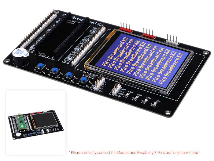
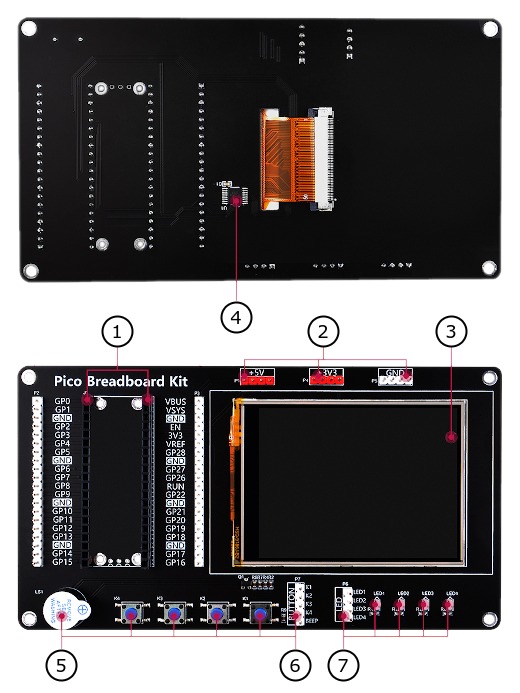
The GeeekPi Pico Breadboard Kit (EP-0164) [1] shield comes with the built-in controller ILI9341 [20] inside the LCD, which is an LCD controller with 240 × RGB × 320 pixels, while the pixels of this 2.8-inch LCD itself is 240 (H) RGB × 320 (V). There are two types of horizontal and vertical screens, so the internal RAM of the LCD is not fully used. The LCD supports 16-bit, and 18-bit, input color formats per pixel, namely RGB565, and RGB666, three color formats. This integration uses the RGB565 color format, which is also a commonly used RGB format. The LCD uses a four-wire SPI communication interface.
Additional there are a resistive Touch Screen (TS) with the TS controller XPT2046 [32].
Features and Resources |
Printed Circuit Board |
5V/40㎃ 0 1 2 3 0 1 2 3 PIEZO LCD/TS 5 (14) (5) 2 1
Design Data |
|
Defective Hardware
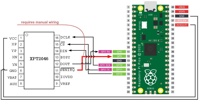
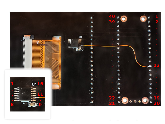
Apart from the fact that the LCD and TSC are connected via unusual pins to the RP2040 and thus the on-chip SPI controllers cannot be used for chip select signal operation to the LCD or TSC, the final interrupt provided by the TSC was not connected. This means that the touch screen of this shield cannot be used out-of-the-box. The TSC will only work with a hardware correction (see figures below). To do this, the /PENIRQ signal from pin 11 of the XPT2046 (U1) must be connected as TP_IRQ signal with GP9 to pin 12 of the Raspberry Pi Pico (W) header (J1) as digital input.
Wiring Diagram |
Printed Circuit Board |
|
|
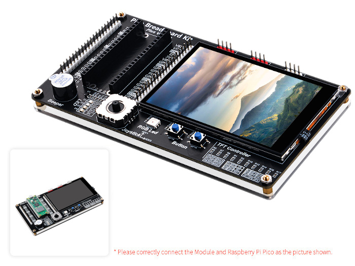
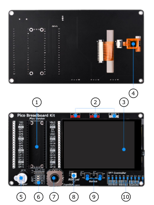
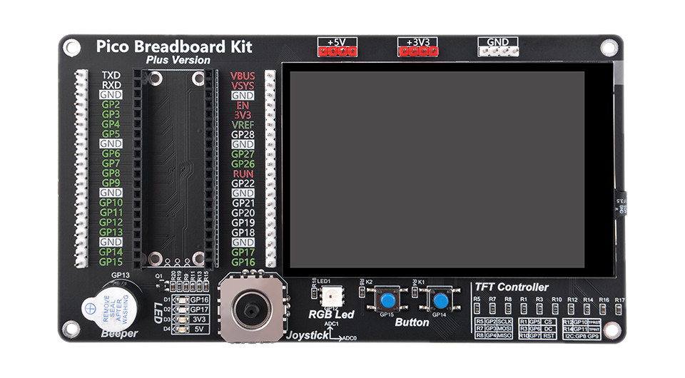
The GeeekPi Pico Breadboard Kit Plus (EP-0172) [5] shield comes with the built-in controller ST7796S [24] inside the LCD, which is an LCD controller with 320 × RGB × 480 pixels, while the pixels of this 3.5-inch LCD itself is 320 (H) RGB × 480 (V). There are two types of horizontal and vertical screens, so the internal RAM of the LCD is not fully used. The LCD supports 16-bit, 18-bit, and 24-bit input color formats per pixel, namely RGB565, RGB666, and RGB888 three color formats. This integration uses the RGB565 color format, which is also a commonly used RGB format. The LCD uses a four-wire SPI communication interface.
Additional there is a capasitive Touch Screen (TS) with the 5-point TS controller GT911 [26] and a standard RGB LED WS2812B [14].
Features and Resources |
Printed Circuit Board |
5V/40㎃ 0 1 analog: UP|DOWN|LEFT|RIGHT 0 1 RGB PIEZO LCD/TS 11 3 2 1 1 1
Design Data |
|
Positions
|
|---|
|
Data Sheets
|
|---|
|
Data Sheets
Pinouts
Pin Mapping |
Pinout |
Default Zephyr Peripheral Mapping
|
|
Pin Mapping |
Pinout |
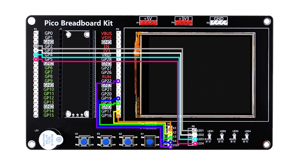
Our advice for connecting the User Buttons and LEDs
To be able to use the User Buttons and LEDs, they must be individually connected to freely available GPIO lines. For this purpose, GP0 to GP5, GP16 to GP22 and also the analog inputs on GP26 to GP28 can be used. The Piezo buzzer must also be connected individually. We recommend the following possible connections, as they are also specified by the shield by default:
This leaves enough options for using the analog inputs and / or the remaining UART or I2C controllers.
Devicetree compatible |
|
Pin Mapping |
Pinout |
Default Zephyr Peripheral Mapping
Devicetree compatible |
|
Utilization
This shields can be used with any development board, shield, or snippet that
provides a Devicetree node with the raspberrypi,pico-header-r3
property for the compatibility. In particular, one SPI bus and some GPIO
signals on this edge connector must be free for communication with the
components on the breadboard shields. The shields also provide the special
Devicetree labels &rpipico_spi_lcd and &lcd_panel for the special
purpose of a on-shield LCD.
For shields with touchscreen support, additional GPIO signals and one I2C bus
on the edge connector must also be free for communication with the touchscreen
controller on the shield. Then the shields also provide the special Devicetree
labels &rpipico_spi_tsc and &tsc_panel for this purpose.
For shields with TF/microSD card slot, even more GPIO signals on the edge
connector must be free for communication with the card on the shield over
SDHC/SPI. Then the shields also provide the special Devicetree labels
&rpipico_spi_sdc and &sdhc_spi for this purpose. In case of
the SDHC/SDIO mode up to seven additional GPIO signals must be free for
communication with the card over a 4-bit SDHC/SDIO interface. But this is
not yet supported and may need changes on the shield hardware.
Programming
Set -DSHIELD=geeekpi_pico_bb and use optional the
USB Console Snippet (usb-console) when you invoke west build.
For example:
Using west:
west build -b rpi_pico -p -S usb-console --shield "geeekpi_pico_bb" -d build/geeekpi_pico_bb-helloshell bridle/samples/helloshell
west flash -r uf2 -d build/geeekpi_pico_bb-helloshell
Using CMake and ninja:
# Use cmake to configure a Ninja-based buildsystem:
cmake -Bbuild/geeekpi_pico_bb-helloshell -GNinja -DBOARD=rpi_pico -DSHIELD=""geeekpi_pico_bb"" bridle/samples/helloshell

# Now run the build tool on the generated build system:
ninja -Cbuild/geeekpi_pico_bb-helloshell flash
Simple test execution on target
(text in bold is a command input)
uart:~$ hello -h
hello - say hello
uart:~$ hello
Hello from shell.
uart:~$ hwinfo devid
Length: 8
ID: 0x8c998be1de969148

uart:~$ kernel version
Zephyr version 4.0.0

uart:~$ bridle version
Bridle version 4.0.0

uart:~$ bridle version long
Bridle version 4.0.0.0

uart:~$ bridle info
Zephyr: 4.0.0
Bridle: 4.0.0-dev
uart:~$ device list
devices:
- clock-controller@40008000 (READY)
  DT node labels: clocks
- reset-controller@4000c000 (READY)
  DT node labels: reset
- snippet_cdc_acm_console_uart (READY)
  DT node labels: snippet_cdc_acm_console_uart
- uart@40034000 (READY)
  DT node labels: uart0 pico_serial rpipico_serial
- timer@40054000 (READY)
  DT node labels: timer
- gpio@40014000 (READY)
  DT node labels: gpio0
- adc@4004c000 (READY)
  DT node labels: adc pico_adc
- flash-controller@18000000 (READY)
  DT node labels: ssi
- pwm@40050000 (READY)
  DT node labels: pwm pico_pwm rpipico_pwm
- vreg@40064000 (READY)
  DT node labels: vreg
- rtc@4005c000 (READY)
  DT node labels: rtc
- pwm_leds (READY)
  DT node labels: pwm_leds
uart:~$ history
[  0] history
[  1] device list
[  2] bridle info
[  3] bridle version long
[  4] bridle version
[  5] kernel version
[  6] hwinfo devid
[  7] hello
[  8] hello -h
Note
PWM LED conflicts with GPIO!
Operations with the user LEDs in PWM mode will fail when ever the corresponding GPIO line was configured as digital output. This condition is irreversible at runtime within the shell and requires a system reset.
Operate with the user LED 0 at PWM2:
uart:~$ led on pwm_leds 0
pwm_leds: turning on LED 0
uart:~$ led set_brightness pwm_leds 0 10
pwm_leds: setting LED 0 brightness to 10
uart:~$ led set_brightness pwm_leds 0 50
pwm_leds: setting LED 0 brightness to 50
uart:~$ led set_brightness pwm_leds 0 100
pwm_leds: setting LED 0 brightness to 100
uart:~$ led off pwm_leds 0
pwm_leds: turning off LED 0
Note
PWM conflicts with GPIO!
Operations with the user LEDs in PWM mode will fail when ever the corresponding GPIO line was configured as digital output. This condition is irreversible at runtime within the shell and requires a system reset.
Operate with the user LED 1 at PWM3:
uart:~$ pwm usec pwm@40050000 3 20000 20000
uart:~$ pwm usec pwm@40050000 3 20000 19000
uart:~$ pwm usec pwm@40050000 3 20000 18000
uart:~$ pwm usec pwm@40050000 3 20000 17000
uart:~$ pwm usec pwm@40050000 3 20000 16000
uart:~$ pwm usec pwm@40050000 3 20000 15000
uart:~$ pwm usec pwm@40050000 3 20000 10000
uart:~$ pwm usec pwm@40050000 3 20000 5000
uart:~$ pwm usec pwm@40050000 3 20000 2500
uart:~$ pwm usec pwm@40050000 3 20000 500
uart:~$ pwm usec pwm@40050000 3 20000 0
Operate with the PIEZO buzzer at GP22 / PWM6 (PWM2CHB):
Piezo resonance: 2,500 ㎑
Piezo high frequency: 10,000 ㎑
uart:~$ pwm usec pwm@40050000 6 400 200
uart:~$ pwm usec pwm@40050000 6 100 50
Note
GPIO conflicts with PWM / PWM LED!
Operations with the user LEDs in PWM mode will fail when ever the corresponding GPIO line was configured as digital output. This condition is irreversible at runtime within the shell and requires a system reset.
Operate with the user LED 1 at GP3:
uart:~$ gpio get gpio@40014000 3
0

uart:~$ gpio conf gpio@40014000 3 oh0
uart:~$ gpio set gpio@40014000 3 1
uart:~$ gpio set gpio@40014000 3 0

uart:~$ gpio blink gpio@40014000 3
Hit any key to exit
Operate with the user key 0 at GP16:
uart:~$ gpio get gpio@40014000 16
1

uart:~$ gpio conf gpio@40014000 16 iul
uart:~$ gpio get gpio@40014000 16
0
uart:~$ gpio get gpio@40014000 16
1
uart:~$ gpio get gpio@40014000 16
0
Using west:
west build -b rpi_pico/rp2040/w -p -S usb-console --shield "geeekpi_pico_bb" -d build/geeekpi_pico_bb-helloshell bridle/samples/helloshell
west flash -r uf2 -d build/geeekpi_pico_bb-helloshell
Using CMake and ninja:
# Use cmake to configure a Ninja-based buildsystem:
cmake -Bbuild/geeekpi_pico_bb-helloshell -GNinja -DBOARD=rpi_pico/rp2040/w -DSHIELD=""geeekpi_pico_bb"" bridle/samples/helloshell

# Now run the build tool on the generated build system:
ninja -Cbuild/geeekpi_pico_bb-helloshell flash
Simple test execution on target
(text in bold is a command input)
uart:~$ hello -h
hello - say hello
uart:~$ hello
Hello from shell.
uart:~$ hwinfo devid
Length: 8
ID: 0x8c998be1de969148

uart:~$ kernel version
Zephyr version 4.0.0

uart:~$ bridle version
Bridle version 4.0.0

uart:~$ bridle version long
Bridle version 4.0.0.0

uart:~$ bridle info
Zephyr: 4.0.0
Bridle: 4.0.0-dev
uart:~$ device list
devices:
- clock-controller@40008000 (READY)
  DT node labels: clocks
- reset-controller@4000c000 (READY)
  DT node labels: reset
- snippet_cdc_acm_console_uart (READY)
  DT node labels: snippet_cdc_acm_console_uart
- uart@40034000 (READY)
  DT node labels: uart0 pico_serial rpipico_serial
- timer@40054000 (READY)
  DT node labels: timer
- gpio@40014000 (READY)
  DT node labels: gpio0
- adc@4004c000 (READY)
  DT node labels: adc pico_adc
- flash-controller@18000000 (READY)
  DT node labels: ssi
- pwm@40050000 (READY)
  DT node labels: pwm pico_pwm rpipico_pwm
- vreg@40064000 (READY)
  DT node labels: vreg
- rtc@4005c000 (READY)
  DT node labels: rtc
- pwm_leds (READY)
  DT node labels: pwm_leds
uart:~$ history
[  0] history
[  1] device list
[  2] bridle info
[  3] bridle version long
[  4] bridle version
[  5] kernel version
[  6] hwinfo devid
[  7] hello
[  8] hello -h
Note
PWM LED conflicts with GPIO!
Operations with the user LEDs in PWM mode will fail when ever the corresponding GPIO line was configured as digital output. This condition is irreversible at runtime within the shell and requires a system reset.
Operate with the user LED 0 at PWM2:
uart:~$ led on pwm_leds 0
pwm_leds: turning on LED 0
uart:~$ led set_brightness pwm_leds 0 10
pwm_leds: setting LED 0 brightness to 10
uart:~$ led set_brightness pwm_leds 0 50
pwm_leds: setting LED 0 brightness to 50
uart:~$ led set_brightness pwm_leds 0 100
pwm_leds: setting LED 0 brightness to 100
uart:~$ led off pwm_leds 0
pwm_leds: turning off LED 0
Note
PWM conflicts with GPIO!
Operations with the user LEDs in PWM mode will fail when ever the corresponding GPIO line was configured as digital output. This condition is irreversible at runtime within the shell and requires a system reset.
Operate with the user LED 1 at PWM3:
uart:~$ pwm usec pwm@40050000 3 20000 20000
uart:~$ pwm usec pwm@40050000 3 20000 19000
uart:~$ pwm usec pwm@40050000 3 20000 18000
uart:~$ pwm usec pwm@40050000 3 20000 17000
uart:~$ pwm usec pwm@40050000 3 20000 16000
uart:~$ pwm usec pwm@40050000 3 20000 15000
uart:~$ pwm usec pwm@40050000 3 20000 10000
uart:~$ pwm usec pwm@40050000 3 20000 5000
uart:~$ pwm usec pwm@40050000 3 20000 2500
uart:~$ pwm usec pwm@40050000 3 20000 500
uart:~$ pwm usec pwm@40050000 3 20000 0
Operate with the PIEZO buzzer at GP22 / PWM6 (PWM2CHB):
Piezo resonance: 2,500 ㎑
Piezo high frequency: 10,000 ㎑
uart:~$ pwm usec pwm@40050000 6 400 200
uart:~$ pwm usec pwm@40050000 6 100 50
Note
GPIO conflicts with PWM / PWM LED!
Operations with the user LEDs in PWM mode will fail when ever the corresponding GPIO line was configured as digital output. This condition is irreversible at runtime within the shell and requires a system reset.
Operate with the user LED 1 at GP3:
uart:~$ gpio get gpio@40014000 3
0

uart:~$ gpio conf gpio@40014000 3 oh0
uart:~$ gpio set gpio@40014000 3 1
uart:~$ gpio set gpio@40014000 3 0

uart:~$ gpio blink gpio@40014000 3
Hit any key to exit
Operate with the user key 0 at GP16:
uart:~$ gpio get gpio@40014000 16
1

uart:~$ gpio conf gpio@40014000 16 iul
uart:~$ gpio get gpio@40014000 16
0
uart:~$ gpio get gpio@40014000 16
1
uart:~$ gpio get gpio@40014000 16
0
on standard 4㎆ revision
Using west:
west build -b waveshare_rp2040_plus -p -S usb-console --shield "geeekpi_pico_bb" -d build/geeekpi_pico_bb-helloshell bridle/samples/helloshell
west flash -r uf2 -d build/geeekpi_pico_bb-helloshell
Using CMake and ninja:
# Use cmake to configure a Ninja-based buildsystem:
cmake -Bbuild/geeekpi_pico_bb-helloshell -GNinja -DBOARD=waveshare_rp2040_plus -DSHIELD=""geeekpi_pico_bb"" bridle/samples/helloshell

# Now run the build tool on the generated build system:
ninja -Cbuild/geeekpi_pico_bb-helloshell flash
on extended 16㎆ revision
Using west:
west build -b waveshare_rp2040_plus@16mb -p -S usb-console --shield "geeekpi_pico_bb" -d build/geeekpi_pico_bb-helloshell bridle/samples/helloshell
west flash -r uf2 -d build/geeekpi_pico_bb-helloshell
Using CMake and ninja:
# Use cmake to configure a Ninja-based buildsystem:
cmake -Bbuild/geeekpi_pico_bb-helloshell -GNinja -DBOARD=waveshare_rp2040_plus@16mb -DSHIELD=""geeekpi_pico_bb"" bridle/samples/helloshell

# Now run the build tool on the generated build system:
ninja -Cbuild/geeekpi_pico_bb-helloshell flash
Simple test execution on target
(text in bold is a command input)
uart:~$ hello -h
hello - say hello
uart:~$ hello
Hello from shell.
uart:~$ hwinfo devid
Length: 8
ID: 0x8c998be1de969148

uart:~$ kernel version
Zephyr version 4.0.0

uart:~$ bridle version
Bridle version 4.0.0

uart:~$ bridle version long
Bridle version 4.0.0.0

uart:~$ bridle info
Zephyr: 4.0.0
Bridle: 4.0.0-dev
uart:~$ device list
devices:
- clock-controller@40008000 (READY)
  DT node labels: clocks
- reset-controller@4000c000 (READY)
  DT node labels: reset
- snippet_cdc_acm_console_uart (READY)
  DT node labels: snippet_cdc_acm_console_uart
- uart@40034000 (READY)
  DT node labels: uart0 pico_serial rpipico_serial
- timer@40054000 (READY)
  DT node labels: timer
- gpio@40014000 (READY)
  DT node labels: gpio0
- adc@4004c000 (READY)
  DT node labels: adc pico_adc
- flash-controller@18000000 (READY)
  DT node labels: ssi
- pwm@40050000 (READY)
  DT node labels: pwm pico_pwm rpipico_pwm
- vreg@40064000 (READY)
  DT node labels: vreg
- rtc@4005c000 (READY)
  DT node labels: rtc
- pwm_leds (READY)
  DT node labels: pwm_leds
uart:~$ history
[  0] history
[  1] device list
[  2] bridle info
[  3] bridle version long
[  4] bridle version
[  5] kernel version
[  6] hwinfo devid
[  7] hello
[  8] hello -h
Note
PWM LED conflicts with GPIO!
Operations with the user LEDs in PWM mode will fail when ever the corresponding GPIO line was configured as digital output. This condition is irreversible at runtime within the shell and requires a system reset.
Operate with the user LED 0 at PWM2:
uart:~$ led on pwm_leds 0
pwm_leds: turning on LED 0
uart:~$ led set_brightness pwm_leds 0 10
pwm_leds: setting LED 0 brightness to 10
uart:~$ led set_brightness pwm_leds 0 50
pwm_leds: setting LED 0 brightness to 50
uart:~$ led set_brightness pwm_leds 0 100
pwm_leds: setting LED 0 brightness to 100
uart:~$ led off pwm_leds 0
pwm_leds: turning off LED 0
Note
PWM conflicts with GPIO!
Operations with the user LEDs in PWM mode will fail when ever the corresponding GPIO line was configured as digital output. This condition is irreversible at runtime within the shell and requires a system reset.
Operate with the user LED 1 at PWM3:
uart:~$ pwm usec pwm@40050000 3 20000 20000
uart:~$ pwm usec pwm@40050000 3 20000 19000
uart:~$ pwm usec pwm@40050000 3 20000 18000
uart:~$ pwm usec pwm@40050000 3 20000 17000
uart:~$ pwm usec pwm@40050000 3 20000 16000
uart:~$ pwm usec pwm@40050000 3 20000 15000
uart:~$ pwm usec pwm@40050000 3 20000 10000
uart:~$ pwm usec pwm@40050000 3 20000 5000
uart:~$ pwm usec pwm@40050000 3 20000 2500
uart:~$ pwm usec pwm@40050000 3 20000 500
uart:~$ pwm usec pwm@40050000 3 20000 0
Operate with the PIEZO buzzer at GP22 / PWM6 (PWM2CHB):
Piezo resonance: 2,500 ㎑
Piezo high frequency: 10,000 ㎑
uart:~$ pwm usec pwm@40050000 6 400 200
uart:~$ pwm usec pwm@40050000 6 100 50
Note
GPIO conflicts with PWM / PWM LED!
Operations with the user LEDs in PWM mode will fail when ever the corresponding GPIO line was configured as digital output. This condition is irreversible at runtime within the shell and requires a system reset.
Operate with the user LED 1 at GP3:
uart:~$ gpio get gpio@40014000 3
0

uart:~$ gpio conf gpio@40014000 3 oh0
uart:~$ gpio set gpio@40014000 3 1
uart:~$ gpio set gpio@40014000 3 0

uart:~$ gpio blink gpio@40014000 3
Hit any key to exit
Operate with the user key 0 at GP16:
uart:~$ gpio get gpio@40014000 16
1

uart:~$ gpio conf gpio@40014000 16 iul
uart:~$ gpio get gpio@40014000 16
0
uart:~$ gpio get gpio@40014000 16
1
uart:~$ gpio get gpio@40014000 16
0
Set -DSHIELD=geeekpi_pico_bb_plus and use optional the
USB Console Snippet (usb-console) when you invoke west build.
For example:
Using west:
west build -b rpi_pico -p -S usb-console --shield "geeekpi_pico_bb_plus" -d build/geeekpi_pico_bb_plus-helloshell bridle/samples/helloshell
west flash -r uf2 -d build/geeekpi_pico_bb_plus-helloshell
Using CMake and ninja:
# Use cmake to configure a Ninja-based buildsystem:
cmake -Bbuild/geeekpi_pico_bb_plus-helloshell -GNinja -DBOARD=rpi_pico -DSHIELD=""geeekpi_pico_bb_plus"" bridle/samples/helloshell

# Now run the build tool on the generated build system:
ninja -Cbuild/geeekpi_pico_bb_plus-helloshell flash
Simple test execution on target
(text in bold is a command input)
uart:~$ hello -h
hello - say hello
uart:~$ hello
Hello from shell.
uart:~$ hwinfo devid
Length: 8
ID: 0x8c998be1de969148

uart:~$ kernel version
Zephyr version 4.0.0

uart:~$ bridle version
Bridle version 4.0.0

uart:~$ bridle version long
Bridle version 4.0.0.0

uart:~$ bridle info
Zephyr: 4.0.0
Bridle: 4.0.0-dev
uart:~$ device list
devices:
- clock-controller@40008000 (READY)
  DT node labels: clocks
- reset-controller@4000c000 (READY)
  DT node labels: reset
- snippet_cdc_acm_console_uart (READY)
  DT node labels: snippet_cdc_acm_console_uart
- uart@40034000 (READY)
  DT node labels: uart0 pico_serial rpipico_serial
- timer@40054000 (READY)
  DT node labels: timer
- pio@50200000 (READY)
  DT node labels: ((pio_hw_t *)0x50200000u) pico_pio0 rpipico_pio
- gpio@40014000 (READY)
  DT node labels: gpio0
- adc@4004c000 (READY)
  DT node labels: adc pico_adc rpipico_adc
- flash-controller@18000000 (READY)
  DT node labels: ssi
- i2c@40044000 (READY)
  DT node labels: i2c0 pico_i2c pico_i2c0 rpipico_i2c rpipico_i2c0 rpipico_i2c_tsc
- pwm@40050000 (READY)
  DT node labels: pwm pico_pwm rpipico_pwm
- vreg@40064000 (READY)
  DT node labels: vreg
- rtc@4005c000 (READY)
  DT node labels: rtc
- pwm_leds (READY)
  DT node labels: pwm_leds
uart:~$ history
[  0] history
[  1] device list
[  2] bridle info
[  3] bridle version long
[  4] bridle version
[  5] kernel version
[  6] hwinfo devid
[  7] hello
[  8] hello -h
Note
PWM LED conflicts with GPIO!
Operations with the user LEDs in PWM mode will fail when ever the corresponding GPIO line was configured as digital output. This condition is irreversible at runtime within the shell and requires a system reset.
Operate with the user LED 0 at PWM0:
uart:~$ led on pwm_leds 0
pwm_leds: turning on LED 0
uart:~$ led set_brightness pwm_leds 0 10
pwm_leds: setting LED 0 brightness to 10
uart:~$ led set_brightness pwm_leds 0 50
pwm_leds: setting LED 0 brightness to 50
uart:~$ led set_brightness pwm_leds 0 100
pwm_leds: setting LED 0 brightness to 100
uart:~$ led off pwm_leds 0
pwm_leds: turning off LED 0
Note
PWM conflicts with GPIO!
Operations with the user LEDs in PWM mode will fail when ever the corresponding GPIO line was configured as digital output. This condition is irreversible at runtime within the shell and requires a system reset.
Operate with the user LED 1 at PWM1:
uart:~$ pwm usec pwm@40050000 1 20000 20000
uart:~$ pwm usec pwm@40050000 1 20000 19000
uart:~$ pwm usec pwm@40050000 1 20000 18000
uart:~$ pwm usec pwm@40050000 1 20000 17000
uart:~$ pwm usec pwm@40050000 1 20000 16000
uart:~$ pwm usec pwm@40050000 1 20000 15000
uart:~$ pwm usec pwm@40050000 1 20000 10000
uart:~$ pwm usec pwm@40050000 1 20000 5000
uart:~$ pwm usec pwm@40050000 1 20000 2500
uart:~$ pwm usec pwm@40050000 1 20000 500
uart:~$ pwm usec pwm@40050000 1 20000 0
Operate with the PIEZO buzzer at GP13 / PWM13 (PWM6CHB):
Piezo resonance: 2,500 ㎑
Piezo high frequency: 10,000 ㎑
uart:~$ pwm usec pwm@40050000 13 400 200
uart:~$ pwm usec pwm@40050000 13 100 50
Note
GPIO conflicts with PWM / PWM LED!
Operations with the user LEDs in PWM mode will fail when ever the corresponding GPIO line was configured as digital output. This condition is irreversible at runtime within the shell and requires a system reset.
Operate with the user LED 1 at GP17:
uart:~$ gpio get gpio@40014000 17
0

uart:~$ gpio conf gpio@40014000 17 oh0
uart:~$ gpio set gpio@40014000 17 1
uart:~$ gpio set gpio@40014000 17 0

uart:~$ gpio blink gpio@40014000 17
Hit any key to exit
Operate with the user key 0 at GP14:
uart:~$ gpio get gpio@40014000 14
1

uart:~$ gpio conf gpio@40014000 14 iul
uart:~$ gpio get gpio@40014000 14
0
uart:~$ gpio get gpio@40014000 14
1
uart:~$ gpio get gpio@40014000 14
0
Operate with the on-shield analog joystick´s X achsis on ADC_CH0:
uart:~$ adc adc@4004c000 resolution 12
uart:~$ adc adc@4004c000 channel id 0
uart:~$ adc adc@4004c000 read 0
read: 2329
uart:~$ adc adc@4004c000 read 0
read: 316
uart:~$ adc adc@4004c000 read 0
read: 4046
Using west:
west build -b rpi_pico/rp2040/w -p -S usb-console --shield "geeekpi_pico_bb_plus" -d build/geeekpi_pico_bb_plus-helloshell bridle/samples/helloshell
west flash -r uf2 -d build/geeekpi_pico_bb_plus-helloshell
Using CMake and ninja:
# Use cmake to configure a Ninja-based buildsystem:
cmake -Bbuild/geeekpi_pico_bb_plus-helloshell -GNinja -DBOARD=rpi_pico/rp2040/w -DSHIELD=""geeekpi_pico_bb_plus"" bridle/samples/helloshell

# Now run the build tool on the generated build system:
ninja -Cbuild/geeekpi_pico_bb_plus-helloshell flash
Simple test execution on target
(text in bold is a command input)
uart:~$ hello -h
hello - say hello
uart:~$ hello
Hello from shell.
uart:~$ hwinfo devid
Length: 8
ID: 0x8c998be1de969148

uart:~$ kernel version
Zephyr version 4.0.0

uart:~$ bridle version
Bridle version 4.0.0

uart:~$ bridle version long
Bridle version 4.0.0.0

uart:~$ bridle info
Zephyr: 4.0.0
Bridle: 4.0.0-dev
uart:~$ device list
devices:
- clock-controller@40008000 (READY)
  DT node labels: clocks
- reset-controller@4000c000 (READY)
  DT node labels: reset
- snippet_cdc_acm_console_uart (READY)
  DT node labels: snippet_cdc_acm_console_uart
- uart@40034000 (READY)
  DT node labels: uart0 pico_serial rpipico_serial
- timer@40054000 (READY)
  DT node labels: timer
- pio@50200000 (READY)
  DT node labels: ((pio_hw_t *)0x50200000u) pico_pio0 rpipico_pio
- gpio@40014000 (READY)
  DT node labels: gpio0
- adc@4004c000 (READY)
  DT node labels: adc pico_adc rpipico_adc
- flash-controller@18000000 (READY)
  DT node labels: ssi
- i2c@40044000 (READY)
  DT node labels: i2c0 pico_i2c pico_i2c0 rpipico_i2c rpipico_i2c0 rpipico_i2c_tsc
- pwm@40050000 (READY)
  DT node labels: pwm pico_pwm rpipico_pwm
- vreg@40064000 (READY)
  DT node labels: vreg
- rtc@4005c000 (READY)
  DT node labels: rtc
- pwm_leds (READY)
  DT node labels: pwm_leds
uart:~$ history
[  0] history
[  1] device list
[  2] bridle info
[  3] bridle version long
[  4] bridle version
[  5] kernel version
[  6] hwinfo devid
[  7] hello
[  8] hello -h
Note
PWM LED conflicts with GPIO!
Operations with the user LEDs in PWM mode will fail when ever the corresponding GPIO line was configured as digital output. This condition is irreversible at runtime within the shell and requires a system reset.
Operate with the user LED 0 at PWM0:
uart:~$ led on pwm_leds 0
pwm_leds: turning on LED 0
uart:~$ led set_brightness pwm_leds 0 10
pwm_leds: setting LED 0 brightness to 10
uart:~$ led set_brightness pwm_leds 0 50
pwm_leds: setting LED 0 brightness to 50
uart:~$ led set_brightness pwm_leds 0 100
pwm_leds: setting LED 0 brightness to 100
uart:~$ led off pwm_leds 0
pwm_leds: turning off LED 0
Note
PWM conflicts with GPIO!
Operations with the user LEDs in PWM mode will fail when ever the corresponding GPIO line was configured as digital output. This condition is irreversible at runtime within the shell and requires a system reset.
Operate with the user LED 1 at PWM1:
uart:~$ pwm usec pwm@40050000 1 20000 20000
uart:~$ pwm usec pwm@40050000 1 20000 19000
uart:~$ pwm usec pwm@40050000 1 20000 18000
uart:~$ pwm usec pwm@40050000 1 20000 17000
uart:~$ pwm usec pwm@40050000 1 20000 16000
uart:~$ pwm usec pwm@40050000 1 20000 15000
uart:~$ pwm usec pwm@40050000 1 20000 10000
uart:~$ pwm usec pwm@40050000 1 20000 5000
uart:~$ pwm usec pwm@40050000 1 20000 2500
uart:~$ pwm usec pwm@40050000 1 20000 500
uart:~$ pwm usec pwm@40050000 1 20000 0
Operate with the PIEZO buzzer at GP13 / PWM13 (PWM6CHB):
Piezo resonance: 2,500 ㎑
Piezo high frequency: 10,000 ㎑
uart:~$ pwm usec pwm@40050000 13 400 200
uart:~$ pwm usec pwm@40050000 13 100 50
Note
GPIO conflicts with PWM / PWM LED!
Operations with the user LEDs in PWM mode will fail when ever the corresponding GPIO line was configured as digital output. This condition is irreversible at runtime within the shell and requires a system reset.
Operate with the user LED 1 at GP17:
uart:~$ gpio get gpio@40014000 17
0

uart:~$ gpio conf gpio@40014000 17 oh0
uart:~$ gpio set gpio@40014000 17 1
uart:~$ gpio set gpio@40014000 17 0

uart:~$ gpio blink gpio@40014000 17
Hit any key to exit
Operate with the user key 0 at GP14:
uart:~$ gpio get gpio@40014000 14
1

uart:~$ gpio conf gpio@40014000 14 iul
uart:~$ gpio get gpio@40014000 14
0
uart:~$ gpio get gpio@40014000 14
1
uart:~$ gpio get gpio@40014000 14
0
Operate with the on-shield analog joystick´s X achsis on ADC_CH0:
uart:~$ adc adc@4004c000 resolution 12
uart:~$ adc adc@4004c000 channel id 0
uart:~$ adc adc@4004c000 read 0
read: 2329
uart:~$ adc adc@4004c000 read 0
read: 316
uart:~$ adc adc@4004c000 read 0
read: 4046
on standard 4㎆ revision
Using west:
west build -b waveshare_rp2040_plus -p -S usb-console --shield "geeekpi_pico_bb_plus" -d build/geeekpi_pico_bb_plus-helloshell bridle/samples/helloshell
west flash -r uf2 -d build/geeekpi_pico_bb_plus-helloshell
Using CMake and ninja:
# Use cmake to configure a Ninja-based buildsystem:
cmake -Bbuild/geeekpi_pico_bb_plus-helloshell -GNinja -DBOARD=waveshare_rp2040_plus -DSHIELD=""geeekpi_pico_bb_plus"" bridle/samples/helloshell

# Now run the build tool on the generated build system:
ninja -Cbuild/geeekpi_pico_bb_plus-helloshell flash
on extended 16㎆ revision
Using west:
west build -b waveshare_rp2040_plus@16mb -p -S usb-console --shield "geeekpi_pico_bb_plus" -d build/geeekpi_pico_bb_plus-helloshell bridle/samples/helloshell
west flash -r uf2 -d build/geeekpi_pico_bb_plus-helloshell
Using CMake and ninja:
# Use cmake to configure a Ninja-based buildsystem:
cmake -Bbuild/geeekpi_pico_bb_plus-helloshell -GNinja -DBOARD=waveshare_rp2040_plus@16mb -DSHIELD=""geeekpi_pico_bb_plus"" bridle/samples/helloshell

# Now run the build tool on the generated build system:
ninja -Cbuild/geeekpi_pico_bb_plus-helloshell flash
Simple test execution on target
(text in bold is a command input)
uart:~$ hello -h
hello - say hello
uart:~$ hello
Hello from shell.
uart:~$ hwinfo devid
Length: 8
ID: 0x8c998be1de969148

uart:~$ kernel version
Zephyr version 4.0.0

uart:~$ bridle version
Bridle version 4.0.0

uart:~$ bridle version long
Bridle version 4.0.0.0

uart:~$ bridle info
Zephyr: 4.0.0
Bridle: 4.0.0-dev
uart:~$ device list
devices:
- clock-controller@40008000 (READY)
  DT node labels: clocks
- reset-controller@4000c000 (READY)
  DT node labels: reset
- snippet_cdc_acm_console_uart (READY)
  DT node labels: snippet_cdc_acm_console_uart
- uart@40034000 (READY)
  DT node labels: uart0 pico_serial rpipico_serial
- timer@40054000 (READY)
  DT node labels: timer
- pio@50200000 (READY)
  DT node labels: ((pio_hw_t *)0x50200000u) pico_pio0 rpipico_pio
- gpio@40014000 (READY)
  DT node labels: gpio0
- adc@4004c000 (READY)
  DT node labels: adc pico_adc rpipico_adc
- flash-controller@18000000 (READY)
  DT node labels: ssi
- i2c@40044000 (READY)
  DT node labels: i2c0 pico_i2c pico_i2c0 rpipico_i2c rpipico_i2c0 rpipico_i2c_tsc
- pwm@40050000 (READY)
  DT node labels: pwm pico_pwm rpipico_pwm
- vreg@40064000 (READY)
  DT node labels: vreg
- rtc@4005c000 (READY)
  DT node labels: rtc
- pwm_leds (READY)
  DT node labels: pwm_leds
uart:~$ history
[  0] history
[  1] device list
[  2] bridle info
[  3] bridle version long
[  4] bridle version
[  5] kernel version
[  6] hwinfo devid
[  7] hello
[  8] hello -h
Note
PWM LED conflicts with GPIO!
Operations with the user LEDs in PWM mode will fail when ever the corresponding GPIO line was configured as digital output. This condition is irreversible at runtime within the shell and requires a system reset.
Operate with the user LED 0 at PWM0:
uart:~$ led on pwm_leds 0
pwm_leds: turning on LED 0
uart:~$ led set_brightness pwm_leds 0 10
pwm_leds: setting LED 0 brightness to 10
uart:~$ led set_brightness pwm_leds 0 50
pwm_leds: setting LED 0 brightness to 50
uart:~$ led set_brightness pwm_leds 0 100
pwm_leds: setting LED 0 brightness to 100
uart:~$ led off pwm_leds 0
pwm_leds: turning off LED 0
Note
PWM conflicts with GPIO!
Operations with the user LEDs in PWM mode will fail when ever the corresponding GPIO line was configured as digital output. This condition is irreversible at runtime within the shell and requires a system reset.
Operate with the user LED 1 at PWM1:
uart:~$ pwm usec pwm@40050000 1 20000 20000
uart:~$ pwm usec pwm@40050000 1 20000 19000
uart:~$ pwm usec pwm@40050000 1 20000 18000
uart:~$ pwm usec pwm@40050000 1 20000 17000
uart:~$ pwm usec pwm@40050000 1 20000 16000
uart:~$ pwm usec pwm@40050000 1 20000 15000
uart:~$ pwm usec pwm@40050000 1 20000 10000
uart:~$ pwm usec pwm@40050000 1 20000 5000
uart:~$ pwm usec pwm@40050000 1 20000 2500
uart:~$ pwm usec pwm@40050000 1 20000 500
uart:~$ pwm usec pwm@40050000 1 20000 0
Operate with the PIEZO buzzer at GP13 / PWM13 (PWM6CHB):
Piezo resonance: 2,500 ㎑
Piezo high frequency: 10,000 ㎑
uart:~$ pwm usec pwm@40050000 13 400 200
uart:~$ pwm usec pwm@40050000 13 100 50
Note
GPIO conflicts with PWM / PWM LED!
Operations with the user LEDs in PWM mode will fail when ever the corresponding GPIO line was configured as digital output. This condition is irreversible at runtime within the shell and requires a system reset.
Operate with the user LED 1 at GP17:
uart:~$ gpio get gpio@40014000 17
0

uart:~$ gpio conf gpio@40014000 17 oh0
uart:~$ gpio set gpio@40014000 17 1
uart:~$ gpio set gpio@40014000 17 0

uart:~$ gpio blink gpio@40014000 17
Hit any key to exit
Operate with the user key 0 at GP14:
uart:~$ gpio get gpio@40014000 14
1

uart:~$ gpio conf gpio@40014000 14 iul
uart:~$ gpio get gpio@40014000 14
0
uart:~$ gpio get gpio@40014000 14
1
uart:~$ gpio get gpio@40014000 14
0
Operate with the on-shield analog joystick´s X achsis on ADC_CH0:
uart:~$ adc adc@4004c000 resolution 12
uart:~$ adc adc@4004c000 channel id 0
uart:~$ adc adc@4004c000 read 0
read: 2329
uart:~$ adc adc@4004c000 read 0
read: 316
uart:~$ adc adc@4004c000 read 0
read: 4046
More Samples
Input dump
Prints all input events as defined by the shields Devicetree. See also Zephyr sample: Input dump.
Print the input events related to the on-shield touchscreen panel, the two user keys, and the two analog joystick achsises using the Input subsystem API. That are:
lvgl_pointer { input = &tsc_panel; };tsc_panel: &xpt2046_240x320 {};zephyr,code = <INPUT_KEY_0>;zephyr,code = <INPUT_KEY_1>;zephyr,code = <INPUT_KEY_2>;zephyr,code = <INPUT_KEY_3>;Joystick simulation by longpress codes (≥1000㎳)
short-code = <INPUT_KEY_RIGHT>;short-code = <INPUT_KEY_DOWN>;short-code = <INPUT_KEY_UP>;short-code = <INPUT_KEY_LEFT>;long-code = <INPUT_KEY_ENTER>;long-code = <INPUT_KEY_DOWN>;long-code = <INPUT_KEY_UP>;long-code = <INPUT_KEY_LEFT>;west build -b rpi_pico -p -S usb-console --shield "geeekpi_pico_bb" -d build/geeekpi_pico_bb-input_dump zephyr/samples/subsys/input/input_dump
west flash -r uf2 -d build/geeekpi_pico_bb-input_dump
west build -b rpi_pico/rp2040/w -p -S usb-console --shield "geeekpi_pico_bb" -d build/geeekpi_pico_bb-input_dump zephyr/samples/subsys/input/input_dump
west flash -r uf2 -d build/geeekpi_pico_bb-input_dump
on standard 4㎆ revision
west build -b waveshare_rp2040_plus -p -S usb-console --shield "geeekpi_pico_bb" -d build/geeekpi_pico_bb-input_dump zephyr/samples/subsys/input/input_dump
west flash -r uf2 -d build/geeekpi_pico_bb-input_dump
on extended 16㎆ revision
west build -b waveshare_rp2040_plus@16mb -p -S usb-console --shield "geeekpi_pico_bb" -d build/geeekpi_pico_bb-input_dump zephyr/samples/subsys/input/input_dump
west flash -r uf2 -d build/geeekpi_pico_bb-input_dump
Simple logging output on target
Print the input events related to the on-shield touchscreen panel, the two user keys, and the two analog joystick achsises using the Input subsystem API. That are:
lvgl_pointer { input = &tsc_panel; };tsc_panel: >911_320x480 {};zephyr,code = <INPUT_KEY_0>;zephyr,code = <INPUT_KEY_1>;zephyr,code = <INPUT_ABS_Y>;zephyr,code = <INPUT_KEY_UP>;zephyr,code = <INPUT_KEY_DOWN>;zephyr,code = <INPUT_ABS_X>;zephyr,code = <INPUT_KEY_LEFT>;zephyr,code = <INPUT_KEY_RIGHT>;west build -b rpi_pico -p -S usb-console --shield "geeekpi_pico_bb_plus" -d build/geeekpi_pico_bb_plus-input_dump zephyr/samples/subsys/input/input_dump
west flash -r uf2 -d build/geeekpi_pico_bb_plus-input_dump
west build -b rpi_pico/rp2040/w -p -S usb-console --shield "geeekpi_pico_bb_plus" -d build/geeekpi_pico_bb_plus-input_dump zephyr/samples/subsys/input/input_dump
west flash -r uf2 -d build/geeekpi_pico_bb_plus-input_dump
on standard 4㎆ revision
west build -b waveshare_rp2040_plus -p -S usb-console --shield "geeekpi_pico_bb_plus" -d build/geeekpi_pico_bb_plus-input_dump zephyr/samples/subsys/input/input_dump
west flash -r uf2 -d build/geeekpi_pico_bb_plus-input_dump
on extended 16㎆ revision
west build -b waveshare_rp2040_plus@16mb -p -S usb-console --shield "geeekpi_pico_bb_plus" -d build/geeekpi_pico_bb_plus-input_dump zephyr/samples/subsys/input/input_dump
west flash -r uf2 -d build/geeekpi_pico_bb_plus-input_dump
Simple logging output on target
Sounds from the speaker
Drives an buzzer or speaker that must defined by the shields Devicetree. See also Bridle sample: Buzzer.
Using the PWM driver API with given Piezo Buzzer. That is:
aliases { pwm-buzzer0 = &pwm_buzzer_0; };west build -b rpi_pico -p -S usb-console --shield "geeekpi_pico_bb" -d build/geeekpi_pico_bb-buzzer bridle/samples/buzzer
west flash -r uf2 -d build/geeekpi_pico_bb-buzzer
west build -b rpi_pico/rp2040/w -p -S usb-console --shield "geeekpi_pico_bb" -d build/geeekpi_pico_bb-buzzer bridle/samples/buzzer
west flash -r uf2 -d build/geeekpi_pico_bb-buzzer
on standard 4㎆ revision
west build -b waveshare_rp2040_plus -p -S usb-console --shield "geeekpi_pico_bb" -d build/geeekpi_pico_bb-buzzer bridle/samples/buzzer
west flash -r uf2 -d build/geeekpi_pico_bb-buzzer
on extended 16㎆ revision
west build -b waveshare_rp2040_plus@16mb -p -S usb-console --shield "geeekpi_pico_bb" -d build/geeekpi_pico_bb-buzzer bridle/samples/buzzer
west flash -r uf2 -d build/geeekpi_pico_bb-buzzer
Simple test execution on target
play a beep
play a funky jingle
uart:~$ buzzer beep
uart:~$ buzzer play funkytown
Using the PWM driver API with given Piezo Buzzer. That is:
aliases { pwm-buzzer0 = &pwm_buzzer_0; };west build -b rpi_pico -p -S usb-console --shield "geeekpi_pico_bb_plus" -d build/geeekpi_pico_bb_plus-buzzer bridle/samples/buzzer
west flash -r uf2 -d build/geeekpi_pico_bb_plus-buzzer
west build -b rpi_pico/rp2040/w -p -S usb-console --shield "geeekpi_pico_bb_plus" -d build/geeekpi_pico_bb_plus-buzzer bridle/samples/buzzer
west flash -r uf2 -d build/geeekpi_pico_bb_plus-buzzer
on standard 4㎆ revision
west build -b waveshare_rp2040_plus -p -S usb-console --shield "geeekpi_pico_bb_plus" -d build/geeekpi_pico_bb_plus-buzzer bridle/samples/buzzer
west flash -r uf2 -d build/geeekpi_pico_bb_plus-buzzer
on extended 16㎆ revision
west build -b waveshare_rp2040_plus@16mb -p -S usb-console --shield "geeekpi_pico_bb_plus" -d build/geeekpi_pico_bb_plus-buzzer bridle/samples/buzzer
west flash -r uf2 -d build/geeekpi_pico_bb_plus-buzzer
Simple test execution on target
play a beep
play a funky jingle
uart:~$ buzzer beep
uart:~$ buzzer play funkytown
LED color change
Drives an RGB LED that must defined by the shields Devicetree. See also Zephyr sample: PWM RGB LED.
Hint
The GeeekPi Pico Breadboard Kit doesn’t provide a TriColor ChipLED. This sample is not applicable.
Hint
The GeeekPi Pico Breadboard Kit Plus doesn’t provide a TriColor ChipLED. This sample is not applicable.
LED strip test pattern
Drives an RGB LED strip that must defined by the shields Devicetree. See also Zephyr sample: LED strip.
Hint
The GeeekPi Pico Breadboard Kit doesn’t provide a RGB LED strip. This sample is not applicable.
Using the LED driver API with given LED strip. That is:
aliases { led-strip = &led_strip; };led_strip: &ws2812_1x1 {};west build -b rpi_pico -p -S usb-console --shield "geeekpi_pico_bb_plus" -d build/geeekpi_pico_bb_plus-ledstrip_test zephyr/samples/drivers/led/led_strip
west flash -r uf2 -d build/geeekpi_pico_bb_plus-ledstrip_test
west build -b rpi_pico/rp2040/w -p -S usb-console --shield "geeekpi_pico_bb_plus" -d build/geeekpi_pico_bb_plus-ledstrip_test zephyr/samples/drivers/led/led_strip
west flash -r uf2 -d build/geeekpi_pico_bb_plus-ledstrip_test
on standard 4㎆ revision
west build -b waveshare_rp2040_plus -p -S usb-console --shield "geeekpi_pico_bb_plus" -d build/geeekpi_pico_bb_plus-ledstrip_test zephyr/samples/drivers/led/led_strip
west flash -r uf2 -d build/geeekpi_pico_bb_plus-ledstrip_test
on extended 16㎆ revision
west build -b waveshare_rp2040_plus@16mb -p -S usb-console --shield "geeekpi_pico_bb_plus" -d build/geeekpi_pico_bb_plus-ledstrip_test zephyr/samples/drivers/led/led_strip
west flash -r uf2 -d build/geeekpi_pico_bb_plus-ledstrip_test
Simple logging output on target
LCD Orientation and Bit Order Test
Draw some basic rectangles onto the display. The rectangle colors and positions are chosen so that you can check the orientation of the LCD and correct RGB bit order. See also Zephyr sample: Display.
Using the Display driver API with chosen display. That is:
chosen { zephyr,display = &lcd_panel; };lcd_panel: &ili9341_320x240 {};west build -b rpi_pico -p -S usb-console --shield "geeekpi_pico_bb" -d build/geeekpi_pico_bb-display_test zephyr/samples/drivers/display
west flash -r uf2 -d build/geeekpi_pico_bb-display_test
west build -b rpi_pico/rp2040/w -p -S usb-console --shield "geeekpi_pico_bb" -d build/geeekpi_pico_bb-display_test zephyr/samples/drivers/display
west flash -r uf2 -d build/geeekpi_pico_bb-display_test
on standard 4㎆ revision
west build -b waveshare_rp2040_plus -p -S usb-console --shield "geeekpi_pico_bb" -d build/geeekpi_pico_bb-display_test zephyr/samples/drivers/display
west flash -r uf2 -d build/geeekpi_pico_bb-display_test
on extended 16㎆ revision
west build -b waveshare_rp2040_plus@16mb -p -S usb-console --shield "geeekpi_pico_bb" -d build/geeekpi_pico_bb-display_test zephyr/samples/drivers/display
west flash -r uf2 -d build/geeekpi_pico_bb-display_test

|
|---|
TOP LEFT, TOP RIGHT, BOTTOM RIGHT |
Simple logging output on target
Using the Display driver API with chosen display. That is:
chosen { zephyr,display = &lcd_panel; };lcd_panel: &st7796s_480x320 {};west build -b rpi_pico -p -S usb-console --shield "geeekpi_pico_bb_plus" -d build/geeekpi_pico_bb_plus-display_test zephyr/samples/drivers/display
west flash -r uf2 -d build/geeekpi_pico_bb_plus-display_test
west build -b rpi_pico/rp2040/w -p -S usb-console --shield "geeekpi_pico_bb_plus" -d build/geeekpi_pico_bb_plus-display_test zephyr/samples/drivers/display
west flash -r uf2 -d build/geeekpi_pico_bb_plus-display_test
on standard 4㎆ revision
west build -b waveshare_rp2040_plus -p -S usb-console --shield "geeekpi_pico_bb_plus" -d build/geeekpi_pico_bb_plus-display_test zephyr/samples/drivers/display
west flash -r uf2 -d build/geeekpi_pico_bb_plus-display_test
on extended 16㎆ revision
west build -b waveshare_rp2040_plus@16mb -p -S usb-console --shield "geeekpi_pico_bb_plus" -d build/geeekpi_pico_bb_plus-display_test zephyr/samples/drivers/display
west flash -r uf2 -d build/geeekpi_pico_bb_plus-display_test

|
|---|
TOP LEFT, TOP RIGHT, BOTTOM RIGHT |
Simple logging output on target
LVGL Basic Sample
Displays “Hello World!” in the center of the screen and a counter at the bottom which increments every second. See also Zephyr sample: LVGL basic sample.
Using the LVGL module on top of the Display driver API and the Input subsystem API with chosen display and touchscreen panel. That is:
chosen { zephyr,display = &lcd_panel; };lcd_panel: &ili9341_320x240 {};lvgl_pointer { input = &tsc_panel; };tsc_panel: &xpt2046_240x320 {};Devicetree compatible
west build -b rpi_pico -p -S usb-console -S del-default-aliases --shield "geeekpi_pico_bb" -d build/geeekpi_pico_bb-lvgl_basic zephyr/samples/subsys/display/lvgl
west flash -r uf2 -d build/geeekpi_pico_bb-lvgl_basic
west build -b rpi_pico/rp2040/w -p -S usb-console -S del-default-aliases --shield "geeekpi_pico_bb" -d build/geeekpi_pico_bb-lvgl_basic zephyr/samples/subsys/display/lvgl
west flash -r uf2 -d build/geeekpi_pico_bb-lvgl_basic
on standard 4㎆ revision
west build -b waveshare_rp2040_plus -p -S usb-console -S del-default-aliases --shield "geeekpi_pico_bb" -d build/geeekpi_pico_bb-lvgl_basic zephyr/samples/subsys/display/lvgl
west flash -r uf2 -d build/geeekpi_pico_bb-lvgl_basic
on extended 16㎆ revision
west build -b waveshare_rp2040_plus@16mb -p -S usb-console -S del-default-aliases --shield "geeekpi_pico_bb" -d build/geeekpi_pico_bb-lvgl_basic zephyr/samples/subsys/display/lvgl
west flash -r uf2 -d build/geeekpi_pico_bb-lvgl_basic
Simple test execution on target
uart:~$ lvgl stats memory
Heap at 0x20001510 contains 2047 units in 11 buckets

  bucket#    min units        total      largest      largest
             threshold       chunks      (units)      (bytes)
  -----------------------------------------------------------
        0            1            2            1            4
        1            2            1            2           12
        6           64            1           81          644
       10         1024            1         1336        10684

11348 free bytes, 4520 allocated bytes, overhead = 512 bytes (3.1%)
Using the LVGL module on top of the Display driver API and the Input subsystem API with chosen display and touchscreen panel. That is:
chosen { zephyr,display = &lcd_panel; };lcd_panel: &st7796s_480x320 {};lvgl_pointer { input = &tsc_panel; };tsc_panel: >911_320x480 {};Devicetree compatible
west build -b rpi_pico -p -S usb-console --shield "geeekpi_pico_bb_plus" -d build/geeekpi_pico_bb_plus-lvgl_basic zephyr/samples/subsys/display/lvgl
west flash -r uf2 -d build/geeekpi_pico_bb_plus-lvgl_basic
west build -b rpi_pico/rp2040/w -p -S usb-console --shield "geeekpi_pico_bb_plus" -d build/geeekpi_pico_bb_plus-lvgl_basic zephyr/samples/subsys/display/lvgl
west flash -r uf2 -d build/geeekpi_pico_bb_plus-lvgl_basic
on standard 4㎆ revision
west build -b waveshare_rp2040_plus -p -S usb-console --shield "geeekpi_pico_bb_plus" -d build/geeekpi_pico_bb_plus-lvgl_basic zephyr/samples/subsys/display/lvgl
west flash -r uf2 -d build/geeekpi_pico_bb_plus-lvgl_basic
on extended 16㎆ revision
west build -b waveshare_rp2040_plus@16mb -p -S usb-console --shield "geeekpi_pico_bb_plus" -d build/geeekpi_pico_bb_plus-lvgl_basic zephyr/samples/subsys/display/lvgl
west flash -r uf2 -d build/geeekpi_pico_bb_plus-lvgl_basic
Simple test execution on target
uart:~$ lvgl stats memory
Heap at 0x20001970 contains 6143 units in 13 buckets

  bucket#    min units        total      largest      largest
             threshold       chunks      (units)      (bytes)
  -----------------------------------------------------------
        0            1           30            1            4
        1            2            6            3           20
        2            4            1            4           28
        3            8            2           15          116
        4           16            4           31          244
        6           64            1           81          644
       10         1024            1         1898        15180

17012 free bytes, 28564 allocated bytes, overhead = 3572 bytes (7.3%)
LVGL Widgets Demo
Shows how the widgets look like out of the box using the built-in material theme. See also Zephyr sample: LVGL demos.
Using the LVGL module on top of the Display driver API and the Input subsystem API with chosen display and touchscreen panel. That is:
chosen { zephyr,display = &lcd_panel; };lcd_panel: &ili9341_320x240 {};lvgl_pointer { input = &tsc_panel; };tsc_panel: &xpt2046_240x320 {};Devicetree compatible
west build -b rpi_pico -p -S usb-console -S del-default-aliases --shield "geeekpi_pico_bb" -d build/geeekpi_pico_bb-lvgl_demos zephyr/samples/modules/lvgl/demos -- -DCONFIG_LV_Z_DEMO_WIDGETS=y
west flash -r uf2 -d build/geeekpi_pico_bb-lvgl_demos
west build -b rpi_pico/rp2040/w -p -S usb-console -S del-default-aliases --shield "geeekpi_pico_bb" -d build/geeekpi_pico_bb-lvgl_demos zephyr/samples/modules/lvgl/demos -- -DCONFIG_LV_Z_DEMO_WIDGETS=y
west flash -r uf2 -d build/geeekpi_pico_bb-lvgl_demos
on standard 4㎆ revision
west build -b waveshare_rp2040_plus -p -S usb-console -S del-default-aliases --shield "geeekpi_pico_bb" -d build/geeekpi_pico_bb-lvgl_demos zephyr/samples/modules/lvgl/demos -- -DCONFIG_LV_Z_DEMO_WIDGETS=y
west flash -r uf2 -d build/geeekpi_pico_bb-lvgl_demos
on extended 16㎆ revision
west build -b waveshare_rp2040_plus@16mb -p -S usb-console -S del-default-aliases --shield "geeekpi_pico_bb" -d build/geeekpi_pico_bb-lvgl_demos zephyr/samples/modules/lvgl/demos -- -DCONFIG_LV_Z_DEMO_WIDGETS=y
west flash -r uf2 -d build/geeekpi_pico_bb-lvgl_demos
Note
Resistive touchscreens have low sensitivity. This example can therefore only be accessed with significant restrictions.
|
|---|
Simple test execution on target
uart:~$ lvgl stats memory
Heap at 0x20001650 contains 6143 units in 13 buckets

  bucket#    min units        total      largest      largest
             threshold       chunks      (units)      (bytes)
  -----------------------------------------------------------
        0            1           30            1            4
        1            2            7            3           20
        2            4            1            7           52
        3            8            1           15          116
        4           16            4           31          244
        6           64            1           81          644
       10         1024            1         1915        15316

17116 free bytes, 28460 allocated bytes, overhead = 3572 bytes (7.3%)
Using the LVGL module on top of the Display driver API and the Input subsystem API with chosen display and touchscreen panel. That is:
chosen { zephyr,display = &lcd_panel; };lcd_panel: &st7796s_480x320 {};lvgl_pointer { input = &tsc_panel; };tsc_panel: >911_320x480 {};Devicetree compatible
west build -b rpi_pico -p -S usb-console --shield "geeekpi_pico_bb_plus" -d build/geeekpi_pico_bb_plus-lvgl_demos zephyr/samples/modules/lvgl/demos -- -DCONFIG_LV_Z_DEMO_WIDGETS=y
west flash -r uf2 -d build/geeekpi_pico_bb_plus-lvgl_demos
west build -b rpi_pico/rp2040/w -p -S usb-console --shield "geeekpi_pico_bb_plus" -d build/geeekpi_pico_bb_plus-lvgl_demos zephyr/samples/modules/lvgl/demos -- -DCONFIG_LV_Z_DEMO_WIDGETS=y
west flash -r uf2 -d build/geeekpi_pico_bb_plus-lvgl_demos
on standard 4㎆ revision
west build -b waveshare_rp2040_plus -p -S usb-console --shield "geeekpi_pico_bb_plus" -d build/geeekpi_pico_bb_plus-lvgl_demos zephyr/samples/modules/lvgl/demos -- -DCONFIG_LV_Z_DEMO_WIDGETS=y
west flash -r uf2 -d build/geeekpi_pico_bb_plus-lvgl_demos
on extended 16㎆ revision
west build -b waveshare_rp2040_plus@16mb -p -S usb-console --shield "geeekpi_pico_bb_plus" -d build/geeekpi_pico_bb_plus-lvgl_demos zephyr/samples/modules/lvgl/demos -- -DCONFIG_LV_Z_DEMO_WIDGETS=y
west flash -r uf2 -d build/geeekpi_pico_bb_plus-lvgl_demos
|
|
|---|
Simple test execution on target
uart:~$ lvgl stats memory
Heap at 0x20001970 contains 6143 units in 13 buckets

  bucket#    min units        total      largest      largest
             threshold       chunks      (units)      (bytes)
  -----------------------------------------------------------
        0            1           30            1            4
        1            2            5            2           12
        2            4            1            7           52
        3            8            2           15          116
        4           16            4           31          244
        6           64            1           81          644
       10         1024            1         1898        15180

17016 free bytes, 28564 allocated bytes, overhead = 3568 bytes (7.3%)
TF/microSD Demonstration
This samples and test applications aren’t applicable on all boards. They will be built with activated USB-CDC/ACM console.
Hint
The GeeekPi Pico Breadboard Kit doesn’t provide a TF/microSD card slot. This sample is not applicable.
Hint
The GeeekPi Pico Breadboard Kit Plus doesn’t provide a TF/microSD card slot. This sample is not applicable.