Cytron Maker RP2040
The RP2040 SoC [68] by Raspberry Pi Ltd. is a small sized and low-cost 32-bit dual ARM Cortex-M0+ microcontroller and predestined for versatile board designs. The Cytron Maker RP2040 board series based on this microcontroller offers a wide range with different scaling factors, in size, features and interfaces for communication, input and output.
Supported Boards
Hardware
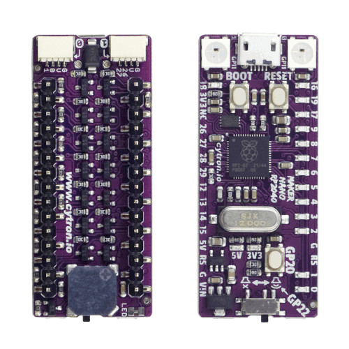
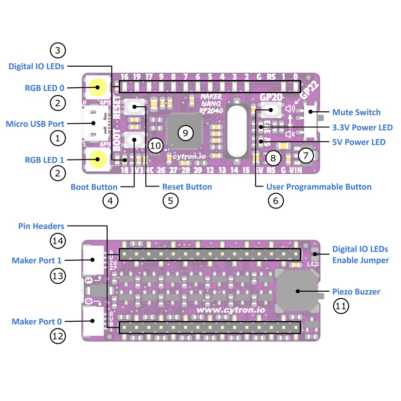
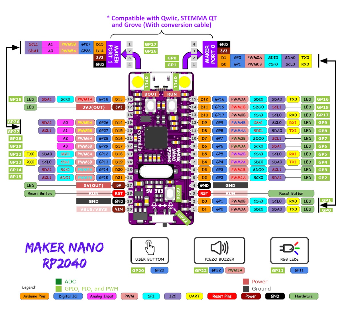
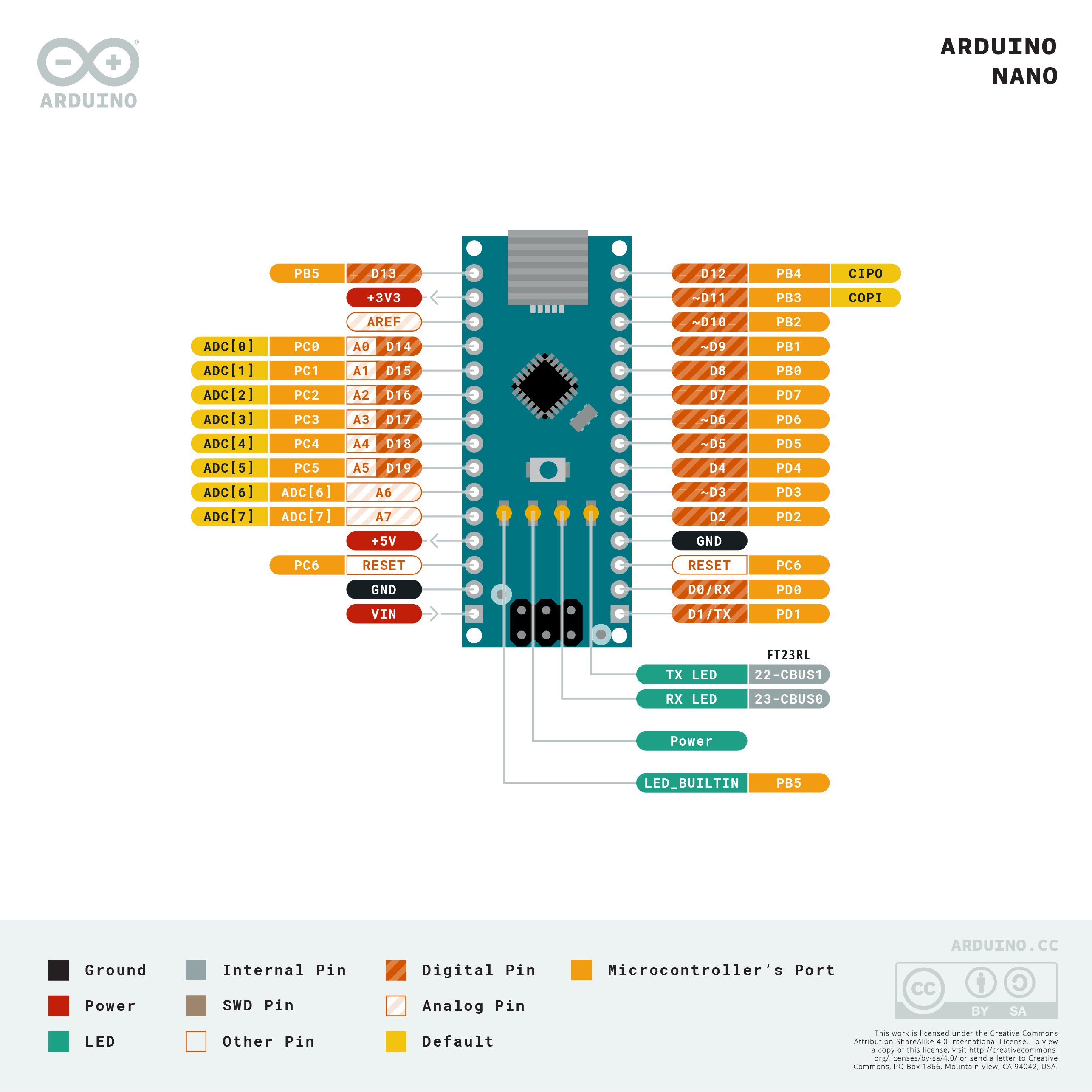
The Maker Nano RP2040 [16] is a nano sized RP2040 development board. The edge pin layout is compatible to the original Arduino Nano with ATmega328P processor but comes with significantly more on-board flash memory, with an on-board piezo buzzer, many LEDs for digital signal diagnostics, two WS2812 Neopixel RGB LEDs and two maker ports compatible with Sparkfun’s Qwiic and Adafruit’s STEMMA QT modules. By using the included conversion cables, maker ports are compatible with Seeed Studio’s Grove System [22] modules too. Main differences compared to the original Arduino Nano:
The IO voltage is only 3.3V and it’s not 5V compatible.
There are only four ADC inputs (A0 - A3) instead of eight (A0 - A7).
Features and Resources |
Printed Circuit Board |
5V/430㎃ 3.3V/500㎃ 5V/3.3V(OUT) 133㎒ 2㎆ 264㎅ USB-B UF2 SWD RST BOOT USER BLUE RGB PIEZO 22 16 3 2 1 1
Design Data
|
|
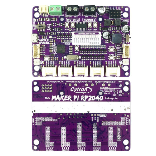
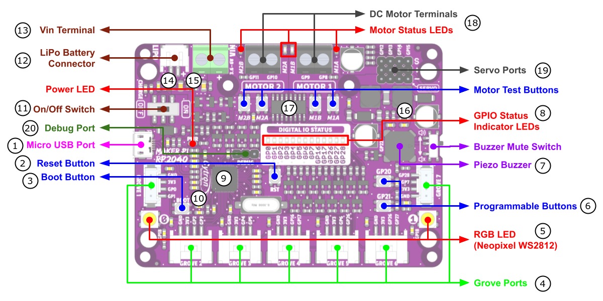
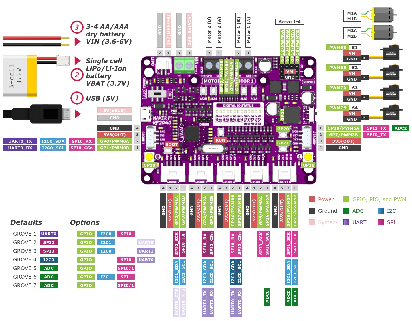
The Maker Pi RP2040 [19] is a special sized RP2040 development board designed for robot applications. This board comes with dual channel DC motor (H-bridge) driver, 4 servo motor (PWM) ports and 7 Grove System [22] connectors, ready for robot or motion control projects. The DC motor driver on-board is able to control 2 brushed DC motors or 1 bipolar/unipolar stepper motor rated from 3.6V to 6V, providing up to 1A current per channel. The built-in quick test buttons and motor output LEDs allow functional test of the motor driver in a quick and convenient way, without the need of writing any code. Vmotor for both DC and servo motors depends on the input voltage supplied to the board. It too has lots of LEDs useful for troubleshooting, is able to make quite some noise with the on-board piezo buzzer and comes with push buttons ready to detect your touch. There are three ways to supply power to the board: via USB (5V) socket, with a single cell LiPo/Li-Ion battery or through the VIN (3.6-6V) terminals. Power supply from all these power sources can all be controlled with the power on/off switch on-board.
Features and Resources |
Printed Circuit Board |
5V/500㎃ 3.3V/300㎃ 3.6-6V/1A(Vmotor/Vbat) Vmotor/3.3V(OUT) 133㎒ 2㎆ 264㎅ USB-B LiPo/Fe UF2 SWD RST BOOT USER BLUE RGB PIEZO DC Motor Servo Motor 13 8 3 2 1 1
Design Data |
|
Positions
|
|---|
|
Data Sheets
|
|---|
|
Data Sheets
Pinouts
The peripherals of the RP2040 SoC [68] can be routed to various pins on the board. The configuration of these routes can be modified through DTS. Please refer to the datasheet to see the possible routings for each peripheral. The default assignments for the various Cytron Maker RP2040 boards are defined below separately in a single tab.
External pin mapping on the Maker Nano RP2040 is identical to the original Raspberry Pi Pico board, but note that there are only analog channels A0 - A3 connected to an ADC and the analog channels A4 - A7 are simple digital signal lines. Also all IO voltage levels are limited to 3.3V only.
Pin Mapping |
Pinout |
Default Zephyr Peripheral Mapping (Arduino Nano R3)
Default Zephyr Peripheral Mapping (Maker Port 0)
Default Zephyr Peripheral Mapping (Maker Port 1)
Default Zephyr On-Board Mapping
Devicetree compatible |
|
External pin mapping on the Maker Pi RP2040 is not identical to any other standard edge connector, except the 7 Grove System [22] connectors. Note that only analog channel A0 - A2 are connected to the outside. GPIO line 29 will be used on-board as analog channel A3 for VM/2 voltage monitoring per default.
Pin Mapping |
Pinout |
Default Zephyr Peripheral Mapping (Grove 1)
Default Zephyr Peripheral Mapping (Grove 2)
Default Zephyr Peripheral Mapping (Grove 3)
Default Zephyr Peripheral Mapping (Grove 4)
Default Zephyr Peripheral Mapping (Grove 5)
Default Zephyr Peripheral Mapping (Grove 6)
Default Zephyr Peripheral Mapping (Grove 7)
Default Zephyr On-Board Mapping
Devicetree compatible |
|
Supported Features
Similar to the Raspberry Pi Pico the Cytron Maker RP2040 board configuration supports the following hardware features:
Peripheral |
Kconfig option |
Devicetree compatible |
Zephyr API |
|---|---|---|---|
PINCTRL |
|||
GPIO |
|||
UART |
|||
UDC (USB Device Controller) |
|||
I2C |
|||
SPI |
|||
PWM |
|||
ADC |
|||
Temperature (Sensor) |
|||
RTC |
|||
Timer (Counter) |
|||
Watchdog Timer (WDT) |
|||
Flash |
|||
PIO |
N/A |
||
UART (PIO) |
|||
SPI (PIO) |
|||
DMA |
|||
HWINFO |
N/A |
||
VREG |
|||
RESET |
|||
CLOCK |
|||
NVIC |
N/A |
Nested Vector Interrupts Controller |
|
SYSTICK |
N/A |
Other hardware features are not currently supported by Zephyr. The default configuration can be found in the different Kconfig files:
Board Configurations
The Cytron Maker RP2040 boards can be configured for the following different use cases.
west build -b cytron_maker_nano_rp2040
Use the serial port UART0 on edge header as Zephyr console and for the shell.
west build -b cytron_maker_nano_rp2040 -S usb-console
Use the native USB device port with CDC-ACM as Zephyr console and for the shell.
west build -b cytron_maker_pi_rp2040
Use the serial port UART0 on edge header as Zephyr console and for the shell.
west build -b cytron_maker_pi_rp2040 -S usb-console
Use the native USB device port with CDC-ACM as Zephyr console and for the shell.
Connections and IOs
The Cytron Marktplace [15] has detailed information about board connections. Download the different schematics or datasheets as linked above per board for more details. The pinout diagrams can also be found there.
Laced Grove Signal Interface
Both the Maker Nano RP2040 and the Maker Pi RP2040 offer the option of
connecting hardware modules via a variety of Grove connectors.
These are provided by a specific interface for general signal mapping, the
Laced Grove Signal Interface.
Following mappings are well known:
grove_gpios: GPIO mapping
grove_pwms: PWM mapping
In addition to the Arduino Nano R3 header, there are also
2 Grove connectors (Qwiic/STEMMA QT).
This is the GPIO signal line mapping from the Arduino Nano R3 [5]
header bindet with arduino-nano-header-r3 to the set
of Grove connectors provided as Laced Grove Signal Interface.
This list must not be stable!
phandle index to shield –> |
Signal : Meaning |
|
|---|---|---|
|
D0: UART-RX (GP1:UART0/LED) |
<&grove_d1_header 0 …>↳
<&arduino_nano_header 0 …>↳
<&gpio0 1 …> |
|
D1: UART-TX (GP0:UART0/LED) |
<&grove_d1_header 1 …>↳
<&arduino_nano_header 1 …>↳
<&gpio0 0 …> |
|
D2: DIO2 (GP2:LED) |
not wired |
|
D3: DIO3/PWM3 (GP3:PWM1CHB/LED) |
not wired |
|
D4: DIO4 (GP4:LED) |
not wired |
|
D5: DIO5/PWM5 (GP5:PWM2CHB/LED) |
not wired |
|
D6: DIO6/PWM6 (GP6:PWM3CHA/LED) |
not wired |
|
D7: DIO7 (GP7:LED) |
not wired |
|
D8: DIO8 (GP8:LED) |
not wired |
|
D9: DIO9/PWM9 (GP9:PWM4CHB/LED/BL) |
not wired |
|
D10: SPI-CS (GP17:SPI0/PWM0CHB/LED) |
not wired |
|
D11: SPI-COPI (GP19:SPI0/PWM1CHB/LED) |
not wired |
|
D12: SPI-CIPO (GP16:SPI0/LED) |
not wired |
|
D13: SPI-CLK (GP18:SPI0/LED) |
not wired |
|
A0/D14: I2C-SDA (GP26:I2C1) |
<&grove_d27_header 1 …>,↳
<&arduino_header 14 …>↳
<&gpio0 26 …> |
|
A1/D15: I2C-SCL (GP27:I2C1) |
<&grove_d27_header 0 …>↳
<&arduino_header 15 …>↳
<&gpio0 27 …> |
|
A2/D16: ADC2 (GP28:ADC) |
not wired |
|
A3/D17: ADC3 (GP29:ADC) |
not wired |
|
A4/D18: I2C-SDA (GP12:I2C0) |
not wired |
|
A5/D19: I2C-SCL (GP13:I2C0) |
not wired |
|
A6: ADC6 (GP14) |
not wired, digital only |
|
A7: ADC7 (GP15) |
not wired, digital only |
|
||
|
||
|
||
|
||
|
||
|
||
|
||
|
||
|
||
|
The corresponding mapping is always board or SOC specific.
In addition to the PWM signal line mapping, the valid
references to the PWM function units in the SOC or on the
board are therefore also defined as Grove PWM Labels.
The following table reflects the currently supported mapping
for cytron_maker_nano_rp2040, but this list will be
growing up with further development and maintenance.
This list must not be complete or stable!
Grove PWM Label |
phandle index to shield –> |
Signal : Meaning |
|
|---|---|---|---|
|
|
D0: UART-RX |
|
|
|
D1: UART-TX |
|
|
D2: DIO2 |
not wired (PWM1CHA) |
|
|
D3: DIO3/PWM3 |
not wired (PWM1CHB) |
|
|
D4: DIO4 |
not wired (PWM2CHA) |
|
|
D5: DIO5/PWM5 |
not wired (PWM2CHB) |
|
|
D6: DIO6/PWM6 |
not wired (PWM3CHA) |
|
|
D7: DIO7 |
not wired (PWM3CHB) |
|
|
D8: DIO8 |
not wired (PWM4CHA) |
|
|
D9: DIO9/PWM9 |
not wired (PWM4CHB) |
|
|
D10: SPI-CS |
not wired (PWM0CHB) |
|
|
D11: SPI-COPI |
not wired (PWM1CHB) |
|
|
D12: SPI-CIPO |
not wired (PWM0CHA) |
|
|
D13: SPI-CLK |
not wired (PWM1CHA) |
|
|
|
A0/D14: I2C-SDA |
|
|
|
A1/D15: I2C-SCL |
|
|
A2/D16: ADC2 |
not wired (PWM6CHA) |
|
|
A3/D17: ADC3 |
not wired (PWM6CHB) |
|
|
A4/D18: I2C-SDA |
not wired (PWM6CHA) |
|
|
A5/D19: I2C-SCL |
not wired (PWM6CHB) |
|
|
A6: ADC6 |
not wired (PWM7CHA) |
|
|
A7: ADC7 |
not wired (PWM7CHB) |
|
|
|||
|
|||
|
|||
|
|||
|
|||
|
|||
|
|||
|
|||
|
|||
|
In addition to the on-board hader for DC and servo motors, there are also
7 Grove connectors (Qwiic/STEMMA QT).
This is the GPIO signal line mapping from the RP2040 SOC [68]
to the set of Grove connectors provided as Laced Grove Signal Interface.
This list must not be stable!
phandle index to shield –> |
Signal : Meaning |
|
|---|---|---|
|
GP0: UART-TX (UART0/PWM0CHA/LED) |
<&grove_d1_header 1 …>↳
<&gpio0 0 …> |
|
GP1: UART-RX (UART0/PWM0CHB/LED) |
<&grove_d1_header 0 …>↳
<&gpio0 1 …> |
|
GP2: SPI-CLK (SPI0/PWM1CHA/LED) |
<&grove_d3_header 1 …>↳
<&gpio0 2 …> |
|
GP3: SPI-MOSI (SPI0/PWM1CHB/LED) |
<&grove_d3_header 0 …>↳
<&gpio0 3 …> |
|
GP4: SPI-MISO (SPI0/PWM2CHA/LED) |
<&grove_d5_header 1 …>↳
<&gpio0 4 …> |
|
GP5: SPI-CS (SPI0/PWM2CHB/LED) |
<&grove_d5_header 0 …>↳
<&gpio0 5 …> |
|
GP6: DIO6 (PWM3CHA/LED) |
<&grove_d26_header 1 …>↳
<&gpio0 6 …> |
|
GP7: DIO7 (PWM3CHB/LED/BL) |
<&grove_d28_header 1 …>↳
<&gpio0 7 …> |
|
GP8: M1A (PWM4CHA) |
not wired (DC Motor 1A) |
|
GP9: M1B (PWM4CHB) |
not wired (DC Motor 1B) |
|
GP10: M2A (PWM5CHA) |
not wired (DC Motor 2A) |
|
GP11: M2B (PWM5CHB) |
not wired (DC Motor 2B) |
|
GP12: SM1 (PWM6CHA) |
not wired (Servo Motor 1) |
|
GP13: SM2 (PWM6CHB) |
not wired (Servo Motor 2) |
|
GP14: SM3 (PWM7CHA) |
not wired (Servo Motor 3) |
|
GP15: SM4 (PWM7CHB) |
not wired (Servo Motor 4) |
|
GP16: I2C-SDA (I2C0/PWM0CHA/LED) |
<&grove_d17_header 1 …>↳
<&gpio0 16 …> |
|
GP17: I2C-SCL (I2C0/PWM0CHB/LED) |
<&grove_d17_header 0 …>↳
<&gpio0 17 …> |
|
GP18: WS2812 (PWM1CHA) |
not wired (RGB LED) |
|
GP19 |
not wired |
|
GP20: B1 (PWM2CHA) |
not wired (Button 1) |
|
GP21: B2 (PWM2CHB) |
not wired (Button 2) |
|
GP22: BZ (PWM3CHA) |
not wired (Buzzer) |
|
GP23 |
not wired |
|
GP24 |
not wired |
|
GP25 |
not wired |
|
GP26: ADC0/DIO26 (ADC/PWM5CHA/LED) |
<&grove_d26_header 0 …>,↳
<&grove_d27_header 1 …>↳
<&gpio0 26 …> |
|
GP27: ADC1/DIO27 (ADC/PWM5CHB/LED) |
<&grove_d27_header 0 …>↳
<&gpio0 27 …> |
|
GP28: ADC2/DIO28 (ADC/PWM6CHA/LED) |
<&grove_d28_header 0 …>↳
<&gpio0 28 …> |
|
GP29: ADC3 (ADC/PWM6CHB) |
not wired (ADC3 @ VMotor/2) |
|
||
|
The corresponding mapping is always board or SOC specific.
In addition to the PWM signal line mapping, the valid
references to the PWM function units in the SOC or on the
board are therefore also defined as Grove PWM Labels.
The following table reflects the currently supported mapping
for cytron_maker_nano_rp2040, but this list will be
growing up with further development and maintenance.
This list must not be complete or stable!
Grove PWM Label |
phandle index to shield –> |
Signal : Meaning |
|
|---|---|---|---|
|
|
GP0: UART-TX |
|
|
|
GP1: UART-RX |
|
|
|
GP2: SPI-CLK |
|
|
|
GP3: SPI-MOSI |
|
|
|
GP4: SPI-MISO |
|
|
|
GP5: SPI-CS |
|
|
|
GP6: GPIO |
|
|
|
GP7: GPIO (LED/BL) |
|
|
GP8: M1A |
not wired (PWM4CHA) |
|
|
GP9: M1B |
not wired (PWM4CHB) |
|
|
GP10: M2A |
not wired (PWM5CHA) |
|
|
GP11: M2B |
not wired (PWM5CHB) |
|
|
GP12: SM1 |
not wired (PWM6CHA) |
|
|
GP13: SM2 |
not wired (PWM6CHB) |
|
|
GP14: SM3 |
not wired (PWM7CHA) |
|
|
GP15: SM4 |
not wired (PWM7CHB) |
|
|
|
GP16: I2C-SDA |
|
|
|
GP17: I2C-SCL |
|
|
GP18: WS2812 |
not wired (PWM1CHA) |
|
|
GP19 |
not wired (PWM1CHB) |
|
|
GP20: B1 |
not wired (PWM2CHA) |
|
|
GP21: B2 |
not wired (PWM2CHB) |
|
|
GP22: BZ |
not wired (PWM3CHA) |
|
|
GP23 |
not wired (PWM3CHB) |
|
|
GP24 |
not wired (PWM4CHA) |
|
|
GP25 |
not wired (PWM4CHB) |
|
|
|
GP26: ADC0 |
|
|
|
GP27: ADC1 |
|
|
|
GP28: ADC2 |
|
|
GP29: ADC3 |
not wired (PWM6CHB) |
|
|
|||
|
System Clock
The RP2040 [68] MCU is configured to use the 12㎒ external crystal with the on-chip PLL generating the 125㎒ system clock. The internal AHB and APB units are set up in the same way as the upstream Raspberry Pi Pico C/C++ SDK [7] libraries.
GPIO (PWM) Ports
The RP2040 [68] MCU has 1 GPIO cell which covers all I/O pads and
8 PWM function unit each with 2 channels beside a dedicated Timer unit. On
the Maker Nano RP2040, almost all 16 PWM channels are available on the edge
connectors, although some channels are occupied by special signals if their
function is enabled. On Maker Pi RP2040 the channels PWM4 A to PWM5 B are
reserved for the on-board DC motor H-bridge driver and also PWM5 A to PWM7 B
for driving servo motors. The PWM3 channel A will be used for the on-board
Piezo buzzer on the two boards Maker Nano RP2040 and Maker Pi RP2040.
But the PWM operation is not enable by default. Only if
CONFIG_PWM_RPI_PICO is enabled then the first user LED or
Piezo buzzer is driven by PWM instead of by GPIO.
ADC/TS Ports
The RP2040 [68] MCU has 1 ADC with 4 channels and an additional
fifth channel for the on-chip temperature sensor (TS). The ADC channels 0-3
are available on the Arduino Nano R3 header, channel 0-1 also on one of the
two Qwiic / STEMMA QT compatiple connectors on Maker Nano RP2040, but this
is not the default pin operation. On Maker Pi RP2040 only the ADC channel
0-2 are available on three of the four Grove compatiple connectors, ADC
channel 3 will be used for internal on-board voltage monitoring.
The external voltage reference ADC_VREF is directly connected to the 3.3V power supply.
SPI Port
The RP2040 [68] MCU has 2 SPIs. The serial bus SPI0 is connect to
external devices over GP19 (MOSI), GP16 (MISO), GP18 (SCK), and GP17 (CSn)
on the Arduino Nano R3 header of Maker Nano RP2040 or over GP3 (MOSI),
GP4 (MISO), GP2 (SCK), and GP5 (CSn) by two Grove compatiple connectors on
the Maker Pi RP2040. SPI1 is not available in any default setup.
I2C Port
The RP2040 [68] MCU has 2 I2Cs. The serial bus I2C0 and I2C1 are
connect to external devices over GP12 (I2C0_SDA), GP13 (I2C0_SCL),
GP26 (I2C1_SDA), and GP27 (I2C1_SCL) on the Arduino Nano R3 header of
Maker Nano RP2040 or over GP16 (I2C0_SDA), GP17 (I2C0_SCL) by default or
alternatively over GP4 (I2C0_SDA), GP5 (I2C0_SCL), GP2 (I2C1_SDA) and
GP3 (I2C1_SCL) on the Grove compatiple connectors on the Maker Pi RP2040.
Serial Port
The RP2040 [68] MCU has 2 UARTs. One of the UARTs (UART0) is connected to external devices over GP0 (TX) and GP1 (RX) on both the Maker Nano RP2040 and the Maker Pi RP2040 header in same manner and is the Zephyr console.
USB Device Port
The RP2040 [68] MCU has a (native) USB device port that can be used to communicate with a host PC. See the USB device support sample applications for more, such as the USB CDC-ACM sample which sets up a virtual serial port that echos characters back to the host PC. As an alternative to the default Zephyr console on serial port the Bridle USB Console Snippet (usb-console) can be used to enable CDC ACM and switch the console to USB:
USB device idVendor=2e8a, idProduct=000a, bcdDevice= 4.01
USB device strings: Mfr=1, Product=2, SerialNumber=3
Product: Maker Nano RP2040 (CDC ACM)
Manufacturer: Cytron (Raspberry Pi)
SerialNumber: BF002B12140C620C
USB device idVendor=2e8a, idProduct=000a, bcdDevice= 4.01 USB device strings: Mfr=1, Product=2, SerialNumber=3 Product: Maker Pi RP2040 (CDC ACM) Manufacturer: Cytron (Raspberry Pi) SerialNumber: BF002B12140C620C
To integrate specific USB device functions that do not follow a USB standard class, the following alternate identifier numbers are available for the various Cytron Maker RP2040 and RP2350 boards according to the Raspberry Pi USB product ID list [4]:
RP2040
0x1000:0x100F:0x1071:Maker UNO RP2040
0x1074:EDU PICO
0x107E:EDU PICO
0x1093:IRIV IO Controller
RP2350
0x1096:MOTION 2350 Pro
Programmable I/O (PIO)
The RP2040 SoC [68] comes with two PIO periherals. These are two simple co-processors that are designed for I/O operations. The PIOs run a custom instruction set, generated from a custom assembly language. PIO programs are assembled using pioasm, a tool provided by Raspberry Pi. Further information can be found in the Raspberry Pi Pico C/C++ SDK [7] document, section with title “Using PIOASM, the PIO Assembler”.
Zephyr does not (currently) assemble PIO programs. Rather, they should be manually assembled and embedded in source code. An example of how this is done can be found at drivers/serial/uart_rpi_pico_pio.c or drivers/spi/spi_rpi_pico_pio.c.
Programming and Debugging
Flashing
Using UF2
If you don’t have an SWD adapter, you can flash the Cytron Maker RP2040 boards
with a UF2 file. By default, building an app for this board will generate a
build/zephyr/zephyr.uf2 file. If the board is powered on with the
BOOTSEL button pressed, it will appear on the host as a mass
storage device:
USB device idVendor=2e8a, idProduct=0003, bcdDevice= 1.00
USB device strings: Mfr=1, Product=2, SerialNumber=0
Product: RP2 Boot
Manufacturer: Raspberry Pi
SerialNumber: E0C9125B0D9B
The UF2 file should be drag-and-dropped or copied on command line to the device, which will then flash the Cytron Maker RP2040 board.
Each RP2040 SoC [68] ships the UF2 compatible [1] bootloader pico-bootrom [9], a native support in silicon. The full source for the RP2040 bootrom at pico-bootrom [9] includes versions 1, 2 and 3 of the bootrom, which correspond to the B0, B1 and B2 silicon revisions, respectively.
Note that every time you build a program for the RP2040, the Pico SDK selects
an appropriate second stage bootloader based on what kind of external QSPI
Flash type the board configuration you are building for was giving. There
are several versions of boot2 [8] for different flash chips, and each one is
exactly 256 bytes of code which is put right at the start of the eventual
program binary. On Zephyr the boot2 versions are part of the
Raspberry Pi Pico HAL [14] module. Possible selections:
CONFIG_RP2_FLASH_AT25SF128A:CONFIG_RP2_FLASH_GENERIC_03H:CONFIG_RP2_FLASH_IS25LP080:CONFIG_RP2_FLASH_W25Q080:CONFIG_RP2_FLASH_W25X10CL:
All Cytron Maker RP2040 boards set this option to CONFIG_RP2_FLASH_W25Q080.
Further information can be found in the RP2040 Datasheet [69], sections with
title “Bootrom” and “Processor Controlled Boot Sequence”
or Brian Starkey’s Blog article Pico serial bootloader [13]
Using SEGGER JLink
You can flash the Cytron Maker RP2040 boards with a SEGGER JLink debug probe as described in Building, Flashing and Debugging.
Here is an example of building and flashing the Blinky application.
west build -b cytron_maker_pi_rp2040 -p -d build/cytron_maker_rp2040 zephyr/samples/basic/blinky
west flash -r jlink -d build/cytron_maker_rp2040
Using OpenOCD
To use PicoProbe [10] or Raspberry Pi Debug Probe [11], you must configure
udev. Create a file in /etc/udev.rules.d with any name,
and write the line below:
ATTRS{idVendor}=="2e8a", ATTRS{idProduct}=="0004", MODE="660", GROUP="plugdev", TAG+="uaccess"
ATTRS{idVendor}=="2e8a", ATTRS{idProduct}=="000c", MODE="660", GROUP="plugdev", TAG+="uaccess"
This example is valid for the case that the user joins to plugdev
groups.
The Maker Pi RP2040 has an SWD interface that can be used to program and debug the on board RP2040. This interface can be utilized by OpenOCD. To use it with the RP2040, OpenOCD version 0.12.0 or later is needed. If you are using a Debian based system (including RaspberryPi OS, Ubuntu, and more), using the pico_setup.sh [12] script is a convenient way to set up the forked version of OpenOCD. Depending on the interface used (such as JLink), you might need to checkout to a branch that supports this interface, before proceeding. Build and install OpenOCD as described in the README.
Here is an example of building and flashing the Blinky application.
west build -b cytron_maker_pi_rp2040 -p -d build/cytron_maker_rp2040 zephyr/samples/basic/blinky -- \
-DOPENOCD=/usr/local/bin/openocd \
-DOPENOCD_DEFAULT_PATH=/usr/local/share/openocd/scripts \
-DCYTRON_RP2040_DEBUG_ADAPTER=picoprobe
west flash -r openocd -d build/cytron_maker_rp2040
Set the environment variables OPENOCD to
/usr/local/bin/openocd and OPENOCD_DEFAULT_PATH to
/usr/local/share/openocd/scripts. This should work with the OpenOCD
that was installed with the default configuration. This configuration also
works with an environment that is set up by the pico_setup.sh [12] script.
CYTRON_RP2040_DEBUG_ADAPTER specifies what debug adapter is
used for debugging. If CYTRON_RP2040_DEBUG_ADAPTER was not
assigned, cmsis-dap is used by default. The other supported adapters
are picoprobe, raspberrypi-swd, jlink and
blackmagicprobe. How to connect picoprobe and
raspberrypi-swd is described in Getting Started Guide with Raspberry
Pi Pico [6]. Any other SWD debug adapter maybe also work with this configuration.
The value of CYTRON_RP2040_DEBUG_ADAPTER is cached, so it can
be omitted from west flash and west debug if it was
previously set while running west build.
CYTRON_RP2040_DEBUG_ADAPTER is used in an argument to OpenOCD as
"source [find interface/${CYTRON_RP2040_DEBUG_ADAPTER}.cfg]". Thus,
CYTRON_RP2040_DEBUG_ADAPTER needs to be assigned the file name of
the debug adapter.
You can also flash the board with the following command that directly calls OpenOCD (assuming a SEGGER JLink adapter is used):
$ openocd -f interface/jlink.cfg    \
          -c 'transport select swd' \
          -f target/rp2040.cfg      \
          -c "adapter speed 2000"   \
          -c 'targets rp2040.core0' \
          -c 'program path/to/zephyr.elf verify reset exit'
Debugging
The SWD interface can also be used to debug the board. To achieve this, you can either use SEGGER JLink or OpenOCD.
Using SEGGER JLink
Use a SEGGER JLink debug probe and follow the instruction in Building, Flashing and Debugging.
Using OpenOCD
Install OpenOCD as described for flashing the board.
Here is an example for debugging the Blinky application.
west build -b cytron_maker_pi_rp2040 -p -d build/cytron_maker_rp2040 zephyr/samples/basic/blinky -- \
-DOPENOCD=/usr/local/bin/openocd \
-DOPENOCD_DEFAULT_PATH=/usr/local/share/openocd/scripts \
-DCYTRON_RP2040_DEBUG_ADAPTER=raspberrypi-swd
west debug -d build/cytron_maker_rp2040
As with flashing, you can specify the debug adapter by specifying CYTRON_RP2040_DEBUG_ADAPTER at west build time. No needs to specify it at west debug time.
You can also debug with OpenOCD and gdb launching from command-line. Run the following command:
$ openocd -f interface/jlink.cfg    \
          -c 'transport select swd' \
          -f target/rp2040.cfg      \
          -c "adapter speed 2000"   \
          -c 'targets rp2040.core0'
On another terminal, run:
$ gdb-multiarch
Inside gdb, run:
(gdb) tar ext :3333
(gdb) file path/to/zephyr.elf
You can then start debugging the board.
More Samples
LED Blinky and Fade
WS2812 LED Test Pattern by PIO
See also Zephyr sample: LED strip.
west build -b cytron_maker_nano_rp2040 -p -d build/cytron_maker_rp2040 zephyr/samples/drivers/led/led_strip
west flash -r uf2 -d build/cytron_maker_rp2040
Blue User LED Blinky by GPIO
See also Zephyr sample: Blinky.
west build -b cytron_maker_nano_rp2040 -p -d build/cytron_maker_rp2040 zephyr/samples/basic/blinky
west flash -r uf2 -d build/cytron_maker_rp2040
Blue User LED Blinky by PWM
See also Zephyr sample: PWM Blinky.
west build -b cytron_maker_nano_rp2040 -p -d build/cytron_maker_rp2040 zephyr/samples/basic/blinky_pwm
west flash -r uf2 -d build/cytron_maker_rp2040
Blue User LED Fade by PWM
See also Zephyr sample: Fade LED.
west build -b cytron_maker_nano_rp2040 -p -d build/cytron_maker_rp2040 zephyr/samples/basic/fade_led
west flash -r uf2 -d build/cytron_maker_rp2040
Blue User LED On/Off by GPIO Button
See also Zephyr sample: Button.
west build -b cytron_maker_nano_rp2040 -p -d build/cytron_maker_rp2040 zephyr/samples/basic/button
west flash -r uf2 -d build/cytron_maker_rp2040
WS2812 LED Test Pattern by PIO
See also Zephyr sample: LED strip.
west build -b cytron_maker_pi_rp2040 -p -d build/cytron_maker_rp2040 zephyr/samples/drivers/led/led_strip
west flash -r uf2 -d build/cytron_maker_rp2040
Blue User LED Blinky by GPIO
See also Zephyr sample: Blinky.
west build -b cytron_maker_pi_rp2040 -p -d build/cytron_maker_rp2040 zephyr/samples/basic/blinky
west flash -r uf2 -d build/cytron_maker_rp2040
Blue User LED Blinky by PWM
See also Zephyr sample: PWM Blinky.
west build -b cytron_maker_pi_rp2040 -p -d build/cytron_maker_rp2040 zephyr/samples/basic/blinky_pwm
west flash -r uf2 -d build/cytron_maker_rp2040
Blue User LED Fade by PWM
See also Zephyr sample: Fade LED.
west build -b cytron_maker_pi_rp2040 -p -d build/cytron_maker_rp2040 zephyr/samples/basic/fade_led
west flash -r uf2 -d build/cytron_maker_rp2040
Blue User LED On/Off by GPIO Button
See also Zephyr sample: Button.
west build -b cytron_maker_pi_rp2040 -p -d build/cytron_maker_rp2040 zephyr/samples/basic/button
west flash -r uf2 -d build/cytron_maker_rp2040
Hello Shell with USB-CDC/ACM Console
Hello Shell
west build -b cytron_maker_nano_rp2040 -p -S usb-console -d build/cytron_maker_rp2040 bridle/samples/helloshell
west flash -r uf2 -d build/cytron_maker_rp2040
Simple test execution on target
(text in bold is a command input)
uart:~$ hello -h
hello - say hello
uart:~$ hello
Hello from shell.
uart:~$ hwinfo devid
Length: 8
ID: 0xe4629c9593563629

uart:~$ kernel version
Zephyr version 4.1.0

uart:~$ bridle version
Bridle version 4.1.0

uart:~$ bridle version long
Bridle version 4.1.0.0

uart:~$ bridle info
Zephyr: 4.1.0
Bridle: 4.1.0
uart:~$ device list
devices:
- clock-controller@40008000 (READY)
  DT node labels: clocks
- reset-controller@4000c000 (READY)
  DT node labels: reset
- snippet_cdc_acm_console_uart (READY)
  DT node labels: snippet_cdc_acm_console_uart
- uart@40034000 (READY)
  DT node labels: uart0 arduino_nano_serial grove_serial
- timer@40054000 (READY)
  DT node labels: timer
- gpio@40014000 (READY)
  DT node labels: gpio0
- adc@4004c000 (READY)
  DT node labels: adc
- flash-controller@18000000 (READY)
  DT node labels: ssi
- i2c@40048000 (READY)
  DT node labels: i2c1 grove_i2c
- i2c@40044000 (READY)
  DT node labels: i2c0 arduino_nano_i2c
- pwm@40050000 (READY)
  DT node labels: pwm grove_pwm_d0 grove_pwm_d1 grove_pwm_d14 grove_pwm_d15
- vreg@40064000 (READY)
  DT node labels: vreg
- pwm_leds (READY)
  DT node labels: pwm_leds
- dietemp (READY)
  DT node labels: die_temp
uart:~$ history
[  0] history
[  1] device list
[  2] bridle info
[  3] bridle version long
[  4] bridle version
[  5] kernel version
[  6] hwinfo devid
[  7] hello
[  8] hello -h
Operate with the on-chip voltage regulator unit:
uart:~$ regulator vlist vreg@40064000
0.800 V
0.850 V
0.900 V
0.950 V
1.000 V
1.050 V
1.100 V
1.150 V
1.200 V
1.250 V
1.300 V
Trigger a power-of/on sequence:
uart:~$ hwinfo reset_cause
reset caused by:
- pin

uart:~$ regulator disable vreg@40064000
*** Booting Zephyr OS build v4.1.0… (delayed boot 4000ms) ***
Hello World! I'm THE SHELL from cytron_maker_nano_rp2040
uart:~$ hwinfo reset_cause
reset caused by:
- power-on reset
Note
PWM LED conflicts with GPIO!
Operations with the blue user LED in PWM mode will fail when ever the corresponding GPIO line 9 was configured as digital output. This condition is irreversible at runtime within the shell and requires a system reset.
Operate with the blue user LED PWM_LED at GP9 / PWM9 (PWM4CHB):
uart:~$ led on pwm_leds 0
pwm_leds: turning on LED 0
uart:~$ led set_brightness pwm_leds 0 10
pwm_leds: setting LED 0 brightness to 10
uart:~$ led set_brightness pwm_leds 0 50
pwm_leds: setting LED 0 brightness to 50
uart:~$ led set_brightness pwm_leds 0 100
pwm_leds: setting LED 0 brightness to 100
uart:~$ led off pwm_leds 0
pwm_leds: turning off LED 0
Note
PWM conflicts with GPIO!
Operations with the blue user LED in PWM mode will fail when ever the corresponding GPIO line 9 was configured as digital output. This condition is irreversible at runtime within the shell and requires a system reset.
Operate with the blue user LED PWM_LED at GP9 / PWM9 (PWM4CHB):
uart:~$ pwm usec pwm@40050000 9 20000 20000
uart:~$ pwm usec pwm@40050000 9 20000 19000
uart:~$ pwm usec pwm@40050000 9 20000 18000
uart:~$ pwm usec pwm@40050000 9 20000 17000
uart:~$ pwm usec pwm@40050000 9 20000 16000
uart:~$ pwm usec pwm@40050000 9 20000 15000
uart:~$ pwm usec pwm@40050000 9 20000 10000
uart:~$ pwm usec pwm@40050000 9 20000 5000
uart:~$ pwm usec pwm@40050000 9 20000 2500
uart:~$ pwm usec pwm@40050000 9 20000 500
uart:~$ pwm usec pwm@40050000 9 20000 0
Operate with the PIEZO buzzer at GP22 / PWM6 (PWM3CHA):
concert pitch: 440 ㎐
Piezo middle frequency: 1,000 ㎑
Piezo resonance: 2,730 ㎑
Piezo high frequency: 10,000 ㎑
higher frequencies: 11 ㎑, 12 ㎑, 13 ㎑, 14 ㎑, 15 ㎑
uart:~$ pwm usec pwm@40050000 6 2273 1136
uart:~$ pwm usec pwm@40050000 6 2000 1000
uart:~$ pwm usec pwm@40050000 6 366 183
uart:~$ pwm usec pwm@40050000 6 100 50
uart:~$ pwm usec pwm@40050000 6 90 45
uart:~$ pwm usec pwm@40050000 6 83 41
uart:~$ pwm usec pwm@40050000 6 77 39
uart:~$ pwm usec pwm@40050000 6 71 36
uart:~$ pwm usec pwm@40050000 6 66 33
Operate with the blue user LED LED at GP9:
uart:~$ gpio get gpio@40014000 9
0

uart:~$ gpio conf gpio@40014000 9 oh0

uart:~$ gpio set gpio@40014000 9 1
uart:~$ gpio set gpio@40014000 9 0

uart:~$ gpio blink gpio@40014000 9
Hit any key to exit
Operate with the user button BTN1 at GP20:
uart:~$ gpio get gpio@40014000 20
1

uart:~$ gpio conf gpio@40014000 20 il
uart:~$ gpio get gpio@40014000 20
0
uart:~$ gpio get gpio@40014000 20
1
uart:~$ gpio get gpio@40014000 20
0
Operate with the channels:
ADC2, pulled up to 3V3
ADC3, pulled down to GND
on-chip temperature sensor on channel ADC4
uart:~$ adc adc@4004c000 resolution 12
uart:~$ adc adc@4004c000 channel id 2
uart:~$ adc adc@4004c000 channel id 3
uart:~$ adc adc@4004c000 channel id 4
uart:~$ adc adc@4004c000 read 2
read: 4081
uart:~$ adc adc@4004c000 read 3
read: 11
uart:~$ adc adc@4004c000 read 4
read: 746
Operate with the on-chip timer unit:
uart:~$ timer oneshot timer@40054000 0 1000000
timer@40054000: Alarm triggered
uart:~$ flash read flash-controller@18000000 1a31c 40
0001A31C: 63 79 74 72 6f 6e 5f 6d  61 6b 65 72 5f 6e 61 6e |cytron_m aker_nan|
0001A32C: 6f 5f 72 70 32 30 34 30  00 48 65 6c 6c 6f 20 57 |o_rp2040 .Hello W|
0001A33C: 6f 72 6c 64 21 20 49 27  6d 20 54 48 45 20 53 48 |orld! I' m THE SH|
0001A34C: 45 4c 4c 20 66 72 6f 6d  20 25 73 0a 00 28 75 6e |ELL from  %s..(un|
Erase, Write and Verify
uart:~$ flash read flash-controller@18000000 e0000 40
000E0000: ff ff ff ff ff ff ff ff  ff ff ff ff ff ff ff ff |........ ........|
000E0010: ff ff ff ff ff ff ff ff  ff ff ff ff ff ff ff ff |........ ........|
000E0020: ff ff ff ff ff ff ff ff  ff ff ff ff ff ff ff ff |........ ........|
000E0030: ff ff ff ff ff ff ff ff  ff ff ff ff ff ff ff ff |........ ........|

uart:~$ flash test flash-controller@18000000 e0000 1000 2
Erase OK.
Write OK.
Verified OK.
Erase OK.
Write OK.
Verified OK.
Erase-Write-Verify test done.
uart:~$ flash read flash-controller@18000000 e0000 40
000E0000: 00 01 02 03 04 05 06 07  08 09 0a 0b 0c 0d 0e 0f |........ ........|
000E0010: 10 11 12 13 14 15 16 17  18 19 1a 1b 1c 1d 1e 1f |........ ........|
000E0020: 20 21 22 23 24 25 26 27  28 29 2a 2b 2c 2d 2e 2f | !"#$%&' ()*+,-./|
000E0030: 30 31 32 33 34 35 36 37  38 39 3a 3b 3c 3d 3e 3f |01234567 89:;<=>?|

uart:~$ flash page_info e0000
Page for address 0xe0000:
start offset: 0xe0000
size: 4096
index: 224
uart:~$ flash erase flash-controller@18000000 e0000 1000
Erase success.

uart:~$ flash read flash-controller@18000000 e0000 40
000E0000: ff ff ff ff ff ff ff ff  ff ff ff ff ff ff ff ff |........ ........|
000E0010: ff ff ff ff ff ff ff ff  ff ff ff ff ff ff ff ff |........ ........|
000E0020: ff ff ff ff ff ff ff ff  ff ff ff ff ff ff ff ff |........ ........|
000E0030: ff ff ff ff ff ff ff ff  ff ff ff ff ff ff ff ff |........ ........|
The Maker Nano RP2040 has no on-board I2C devices. For this example the Grove Temperature and Barometer Sensor – BMP280 [27] was connected to I2C0.
uart:~$ i2c scan i2c@40044000
     0  1  2  3  4  5  6  7  8  9  a  b  c  d  e  f
00:             -- -- -- -- -- -- -- -- -- -- -- --
10: -- -- -- -- -- -- -- -- -- -- -- -- -- -- -- --
20: -- -- -- -- -- -- -- -- -- -- -- -- -- -- -- --
30: -- -- -- -- -- -- -- -- -- -- -- -- -- -- -- --
40: -- -- -- -- -- -- -- -- -- -- -- -- -- -- -- --
50: -- -- -- -- -- -- -- -- -- -- -- -- -- -- -- --
60: -- -- -- -- -- -- -- -- -- -- -- -- -- -- -- --
70: -- -- -- -- -- -- -- 77
1 devices found on i2c@40044000
The I2C address 0x77 is a Bosch BMP280 Air Pressure Sensor and their
Chip-ID can read from register 0xd0. The Chip-ID must be 0x58:
uart:~$ i2c read_byte i2c@40044000 77 d0
Output: 0x58
uart:~$ sensor info
device name: dietemp, vendor: Raspberry Pi Foundation, model: pico-temp, friendly name: (null)
on-chip temperature sensor
uart:~$ sensor get dietemp
channel type=12(die_temp) index=0 shift=5 num_samples=1 value=140591584104ns (27.581056)
Hello Shell
west build -b cytron_maker_pi_rp2040 -p -S usb-console -d build/cytron_maker_rp2040 bridle/samples/helloshell
west flash -r uf2 -d build/cytron_maker_rp2040
Simple test execution on target
(text in bold is a command input)
uart:~$ hello -h
hello - say hello
uart:~$ hello
Hello from shell.
uart:~$ hwinfo devid
Length: 8
ID: 0xe4629c9593563629

uart:~$ kernel version
Zephyr version 4.1.0

uart:~$ bridle version
Bridle version 4.1.0

uart:~$ bridle version long
Bridle version 4.1.0.0

uart:~$ bridle info
Zephyr: 4.1.0
Bridle: 4.1.0
uart:~$ device list
devices:
- clock-controller@40008000 (READY)
  DT node labels: clocks
- reset-controller@4000c000 (READY)
  DT node labels: reset
- snippet_cdc_acm_console_uart (READY)
  DT node labels: snippet_cdc_acm_console_uart
- uart@40034000 (READY)
  DT node labels: uart0 grove_serial
- timer@40054000 (READY)
  DT node labels: timer
- pio@50200000 (READY)
  DT node labels: ((pio_hw_t *)0x50200000u)
- gpio@40014000 (READY)
  DT node labels: gpio0
- adc@4004c000 (READY)
  DT node labels: adc
- flash-controller@18000000 (READY)
  DT node labels: ssi
- i2c@40044000 (READY)
  DT node labels: i2c0 grove_i2c
- pwm@40050000 (READY)
  DT node labels: pwm grove_pwm_d0 grove_pwm_d1 grove_pwm_d2 grove_pwm_d3 grove_pwm_d4 grove_pwm_d5 grove_pwm_d6 grove_pwm_d7 grove_pwm_d16 grove_pwm_d17 grove_pwm_d26 grove_pwm_d27 grove_pwm_d28
- vreg@40064000 (READY)
  DT node labels: vreg
- pwm_leds (READY)
  DT node labels: pwm_leds
- dietemp (READY)
  DT node labels: die_temp
uart:~$ history
[  0] history
[  1] device list
[  2] bridle info
[  3] bridle version long
[  4] bridle version
[  5] kernel version
[  6] hwinfo devid
[  7] hello
[  8] hello -h
Operate with the on-chip voltage regulator unit:
uart:~$ regulator vlist vreg@40064000
0.800 V
0.850 V
0.900 V
0.950 V
1.000 V
1.050 V
1.100 V
1.150 V
1.200 V
1.250 V
1.300 V
Trigger a power-of/on sequence:
uart:~$ hwinfo reset_cause
reset caused by:
- pin

uart:~$ regulator disable vreg@40064000
*** Booting Zephyr OS build v4.1.0… (delayed boot 4000ms) ***
Hello World! I'm THE SHELL from cytron_maker_pi_rp2040
uart:~$ hwinfo reset_cause
reset caused by:
- power-on reset
Note
PWM LED conflicts with GPIO!
Operations with the blue user LED in PWM mode will fail when ever the corresponding GPIO line 7 was configured as digital output. This condition is irreversible at runtime within the shell and requires a system reset.
Operate with the blue user LED PWM_LED at GP7 / PWM7 (PWM3CHB):
uart:~$ led on pwm_leds 0
pwm_leds: turning on LED 0
uart:~$ led set_brightness pwm_leds 0 10
pwm_leds: setting LED 0 brightness to 10
uart:~$ led set_brightness pwm_leds 0 50
pwm_leds: setting LED 0 brightness to 50
uart:~$ led set_brightness pwm_leds 0 100
pwm_leds: setting LED 0 brightness to 100
uart:~$ led off pwm_leds 0
pwm_leds: turning off LED 0
Note
PWM conflicts with GPIO!
Operations with the blue user LED in PWM mode will fail when ever the corresponding GPIO line 7 was configured as digital output. This condition is irreversible at runtime within the shell and requires a system reset.
Operate with the blue user LED PWM_LED at GP7 / PWM7 (PWM3CHB):
uart:~$ pwm usec pwm@40050000 7 20000 20000
uart:~$ pwm usec pwm@40050000 7 20000 19000
uart:~$ pwm usec pwm@40050000 7 20000 18000
uart:~$ pwm usec pwm@40050000 7 20000 17000
uart:~$ pwm usec pwm@40050000 7 20000 16000
uart:~$ pwm usec pwm@40050000 7 20000 15000
uart:~$ pwm usec pwm@40050000 7 20000 10000
uart:~$ pwm usec pwm@40050000 7 20000 5000
uart:~$ pwm usec pwm@40050000 7 20000 2500
uart:~$ pwm usec pwm@40050000 7 20000 500
uart:~$ pwm usec pwm@40050000 7 20000 0
Operate with the PIEZO buzzer at GP22 / PWM6 (PWM3CHA):
concert pitch: 440 ㎐
Piezo middle frequency: 1,000 ㎑
Piezo resonance: 2,730 ㎑
Piezo high frequency: 10,000 ㎑
higher frequencies: 11 ㎑, 12 ㎑, 13 ㎑, 14 ㎑, 15 ㎑
uart:~$ pwm usec pwm@40050000 6 2273 1136
uart:~$ pwm usec pwm@40050000 6 2000 1000
uart:~$ pwm usec pwm@40050000 6 366 183
uart:~$ pwm usec pwm@40050000 6 100 50
uart:~$ pwm usec pwm@40050000 6 90 45
uart:~$ pwm usec pwm@40050000 6 83 41
uart:~$ pwm usec pwm@40050000 6 77 39
uart:~$ pwm usec pwm@40050000 6 71 36
uart:~$ pwm usec pwm@40050000 6 66 33
Operate with the SERVO motor (≈11 ㎳/° duty cycle, 50 ㎐ period) at GP12 / PWM12 (PWM6CHA):
on 0.500 ㎳ ≲ -90°
on 1.500 ㎳ ≅ 0°
on 2.500 ㎳ ≳ +90°
uart:~$ pwm usec pwm@40050000 12 20000 500
uart:~$ pwm usec pwm@40050000 12 20000 1500
uart:~$ pwm usec pwm@40050000 12 20000 2500
Operate with the blue user LED LED at GP7:
uart:~$ gpio get gpio@40014000 7
0

uart:~$ gpio conf gpio@40014000 7 oh0

uart:~$ gpio set gpio@40014000 7 1
uart:~$ gpio set gpio@40014000 7 0

uart:~$ gpio blink gpio@40014000 7
Hit any key to exit
Operate with the user button BTN1 at GP20:
uart:~$ gpio get gpio@40014000 20
1

uart:~$ gpio conf gpio@40014000 20 il
uart:~$ gpio get gpio@40014000 20
0
uart:~$ gpio get gpio@40014000 20
1
uart:~$ gpio get gpio@40014000 20
0
Operate with the channels:
ADC0, pulled up to 3V3
ADC1, pulled down to GND
ADC3, on-board VM/2 voltage monitoring
on-chip temperature sensor on channel ADC4
uart:~$ adc adc@4004c000 resolution 12
uart:~$ adc adc@4004c000 channel id 0
uart:~$ adc adc@4004c000 channel id 1
uart:~$ adc adc@4004c000 channel id 3
uart:~$ adc adc@4004c000 channel id 4
uart:~$ adc adc@4004c000 read 0
read: 4095
uart:~$ adc adc@4004c000 read 1
read: 4
uart:~$ adc adc@4004c000 read 3
read: 2984
uart:~$ adc adc@4004c000 read 4
read: 742
Operate with the on-chip timer unit:
uart:~$ timer oneshot timer@40054000 0 1000000
timer@40054000: Alarm triggered
uart:~$ flash read flash-controller@18000000 1a358 40
0001A358: 63 79 74 72 6f 6e 5f 6d  61 6b 65 72 5f 70 69 5f |cytron_m aker_pi_|
0001A368: 72 70 32 30 34 30 00 48  65 6c 6c 6f 20 57 6f 72 |rp2040.H ello Wor|
0001A378: 6c 64 21 20 49 27 6d 20  54 48 45 20 53 48 45 4c |ld! I'm  THE SHEL|
0001A388: 4c 20 66 72 6f 6d 20 25  73 0a 00 28 75 6e 73 69 |L from % s..(unsi|
Erase, Write and Verify
uart:~$ flash read flash-controller@18000000 e0000 40
000E0000: ff ff ff ff ff ff ff ff  ff ff ff ff ff ff ff ff |........ ........|
000E0010: ff ff ff ff ff ff ff ff  ff ff ff ff ff ff ff ff |........ ........|
000E0020: ff ff ff ff ff ff ff ff  ff ff ff ff ff ff ff ff |........ ........|
000E0030: ff ff ff ff ff ff ff ff  ff ff ff ff ff ff ff ff |........ ........|

uart:~$ flash test flash-controller@18000000 e0000 1000 2
Erase OK.
Write OK.
Verified OK.
Erase OK.
Write OK.
Verified OK.
Erase-Write-Verify test done.
uart:~$ flash read flash-controller@18000000 e0000 40
000E0000: 00 01 02 03 04 05 06 07  08 09 0a 0b 0c 0d 0e 0f |........ ........|
000E0010: 10 11 12 13 14 15 16 17  18 19 1a 1b 1c 1d 1e 1f |........ ........|
000E0020: 20 21 22 23 24 25 26 27  28 29 2a 2b 2c 2d 2e 2f | !"#$%&' ()*+,-./|
000E0030: 30 31 32 33 34 35 36 37  38 39 3a 3b 3c 3d 3e 3f |01234567 89:;<=>?|

uart:~$ flash page_info e0000
Page for address 0xe0000:
start offset: 0xe0000
size: 4096
index: 224
uart:~$ flash erase flash-controller@18000000 e0000 1000
Erase success.

uart:~$ flash read flash-controller@18000000 e0000 40
000E0000: ff ff ff ff ff ff ff ff  ff ff ff ff ff ff ff ff |........ ........|
000E0010: ff ff ff ff ff ff ff ff  ff ff ff ff ff ff ff ff |........ ........|
000E0020: ff ff ff ff ff ff ff ff  ff ff ff ff ff ff ff ff |........ ........|
000E0030: ff ff ff ff ff ff ff ff  ff ff ff ff ff ff ff ff |........ ........|
The Maker Pi RP2040 has no on-board I2C devices. For this example the Grove Temperature and Barometer Sensor – BMP280 [27] was connected.
uart:~$ i2c scan i2c@40044000
     0  1  2  3  4  5  6  7  8  9  a  b  c  d  e  f
00:             -- -- -- -- -- -- -- -- -- -- -- --
10: -- -- -- -- -- -- -- -- -- -- -- -- -- -- -- --
20: -- -- -- -- -- -- -- -- -- -- -- -- -- -- -- --
30: -- -- -- -- -- -- -- -- -- -- -- -- -- -- -- --
40: -- -- -- -- -- -- -- -- -- -- -- -- -- -- -- --
50: -- -- -- -- -- -- -- -- -- -- -- -- -- -- -- --
60: -- -- -- -- -- -- -- -- -- -- -- -- -- -- -- --
70: -- -- -- -- -- -- -- 77
1 devices found on i2c@40044000
The I2C address 0x77 is a Bosch BMP280 Air Pressure Sensor and their
Chip-ID can read from register 0xd0. The Chip-ID must be 0x58:
uart:~$ i2c read_byte i2c@40044000 77 d0
Output: 0x58
uart:~$ sensor info
device name: dietemp, vendor: Raspberry Pi Foundation, model: pico-temp, friendly name: (null)
on-chip temperature sensor
uart:~$ sensor get dietemp
channel type=12(die_temp) index=0 shift=5 num_samples=1 value=56376680956ns (29.324229)
Input dump with USB-CDC/ACM Console
Prints all input events as defined by the shields Devicetree. See also Zephyr sample: Input dump.
Print the input events related to the one on-board user button using the Input subsystem API. That are:
zephyr,code = <INPUT_KEY_0>;Devicetree compatible
zephyr,lvgl-keypad-inputwith devicetree relationlvgl_keypad: lvgl-keypad { input = <&gpio_keys>; };BTN1 :input-codes = <INPUT_KEY_0>;:lvgl-codes = <LV_KEY_ENTER>;
Button Input Dump
west build -b cytron_maker_nano_rp2040 -p -S usb-console -d build/cytron_maker_rp2040 zephyr/samples/subsys/input/input_dump
west flash -r uf2 -d build/cytron_maker_rp2040
Simple logging output on target
Print the input events related to the two on-board user button using the Input subsystem API. That are:
zephyr,code = <INPUT_KEY_0>;zephyr,code = <INPUT_KEY_1>;Devicetree compatible
zephyr,lvgl-keypad-inputwith devicetree relationlvgl_keypad: lvgl-keypad { input = <&gpio_keys>; };BTN1 :input-codes = <INPUT_KEY_0>;:lvgl-codes = <LV_KEY_ENTER>;BTN2 :input-codes = <INPUT_KEY_1>;:lvgl-codes = <LV_KEY_NEXT>;
Button Input Dump
west build -b cytron_maker_pi_rp2040 -p -S usb-console -d build/cytron_maker_rp2040 zephyr/samples/subsys/input/input_dump
west flash -r uf2 -d build/cytron_maker_rp2040
Simple logging output on target
Sounds from the speaker with USB-CDC/ACM Console
Piezo Buzzer Test
The sample is prepared for the on-board PWM_BUZZER connected to the PWM channel at GP22 / PWM6 (PWM3CHA).
The PWM period is 880 ㎐, twice the concert pitch frequency of 440 ㎐.
 1/ {
 2	aliases {
 3		pwm-buzzer0 = &pwm_buzzer0;
 4	};
 5
 6	pwm_buzzers {
 7		compatible = "pwm-buzzers";
 8		status = "okay";
 9
10		pwm_buzzer0: pwm_buzzer0 {
11			pwms = <&pwm 6 PWM_HZ(880) PWM_POLARITY_NORMAL>;
12			label = "PWM_BUZZER";
13		};
14	};
15};
16
17&pwm {
18	divider-int-3 = <255>;
19};
Invoke west build and west flash:
west build -b cytron_maker_nano_rp2040 -p -S usb-console -d build/cytron_maker_rp2040 bridle/samples/buzzer
west flash -r uf2 -d build/cytron_maker_rp2040
Simple test execution on target
play a beep
play a folk song
play a chrismas song
uart:~$ buzzer beep
uart:~$ buzzer play folksong
uart:~$ buzzer play xmastime
Piezo Buzzer Test
The sample is prepared for the on-board PWM_BUZZER connected to the PWM channel at GP22 / PWM6 (PWM3CHA).
The PWM period is 880 ㎐, twice the concert pitch frequency of 440 ㎐.
 1/ {
 2	aliases {
 3		pwm-buzzer0 = &pwm_buzzer0;
 4	};
 5
 6	pwm_buzzers {
 7		compatible = "pwm-buzzers";
 8		status = "okay";
 9
10		pwm_buzzer0: pwm_buzzer0 {
11			pwms = <&pwm 6 PWM_HZ(880) PWM_POLARITY_NORMAL>;
12			label = "PWM_BUZZER";
13		};
14	};
15};
16
17&pwm {
18	divider-int-3 = <255>;
19};
Invoke west build and west flash:
west build -b cytron_maker_pi_rp2040 -p -S usb-console -d build/cytron_maker_rp2040 bridle/samples/buzzer
west flash -r uf2 -d build/cytron_maker_rp2040
Simple test execution on target
play a beep
play a folk song
play a chrismas song
uart:~$ buzzer beep
uart:~$ buzzer play folksong
uart:~$ buzzer play xmastime
Drive a motor with USB-CDC/ACM Console
Servomotor Test
See also Zephyr sample: Servomotor.
Hint
The Maker Nano RP2040 can’t drive any servo motor without additional equipment. This example is not applicable.
Servomotor Test
The sample is prepared for servomotor PWM_SERVO_0 at first on-board channel at GP12 / PWM12 (PWM6CHA).
 1/ {
 2	aliases {
 3		pwm-servo0 = &pwm_servo0;
 4		pwm-servo1 = &pwm_servo1;
 5		pwm-servo2 = &pwm_servo2;
 6		pwm-servo3 = &pwm_servo3;
 7	};
 8
 9	pwm_servo_motors {
10		compatible = "pwm-servos";
11		status = "okay";
12
13		pwm_servo0: pwm_servo_0 {
14			pwms = <&pwm 12 PWM_MSEC(20) PWM_POLARITY_NORMAL>;
15			label = "PWM_SERVO_0";
16		};
17		pwm_servo1: pwm_servo_1 {
18			pwms = <&pwm 13 PWM_MSEC(20) PWM_POLARITY_NORMAL>;
19			label = "PWM_SERVO_1";
20		};
21		pwm_servo2: pwm_servo_2 {
22			pwms = <&pwm 14 PWM_MSEC(20) PWM_POLARITY_NORMAL>;
23			label = "PWM_SERVO_2";
24		};
25		pwm_servo3: pwm_servo_3 {
26			pwms = <&pwm 15 PWM_MSEC(20) PWM_POLARITY_NORMAL>;
27			label = "PWM_SERVO_3";
28		};
29	};
30};
31
32&pwm {
33	divider-int-6 = <255>;
34	divider-int-7 = <255>;
35};
Connect a servomotor MG996R to the first on-board PWM channel for servomotors, the 4×3 pin header block at position 19. See the board positions diagram for details.
The corresponding PWM pulse widths for a range of -90° to +90° (180°) are 500 ㎲ to 2,500 ㎲ with a period of 50 ㎐. All these servomotor specific parameters are preset by the snippet PWM Servomotor Preset Snippet (pwm-servo) that have to use to get access to this dedicated PWM channel together with the original Zephyr Servomotor sample. Invoke west build and west flash with this snipped and optional mixed with others, for example:
west build -b cytron_maker_pi_rp2040 -p -S usb-console -S pwm-servo -d build/cytron_maker_rp2040 zephyr/samples/basic/servo_motor
west flash -r uf2 -d build/cytron_maker_rp2040
Display Test and Demonstration
This samples and test applications are only applicable together with the Waveshare 2.4 LCD shield. This LCD module have to connected by free wiring.
Connect the Waveshare 2.4 LCD module by free wiring to the
Arduino Nano R3 header. Following module’s pin assignments
for Arduino Nano R3.
Pin |
Pin |
||
17 |
3V3(OUT) |
1 |
VCC |
29 |
GND |
2 |
GND |
14 |
SPI0_TX : D11 |
3 |
DIN COPI ILI9341 Serial Data Input |
16 |
SPI0_SCK : D13 |
4 |
CLK SCK ILI9341 Serial Clock Input |
13 |
SPI0_CSN : D10 |
5 |
CS CSN ILI9341 Chip Select Input |
10 |
GP7 : D7 |
6 |
DC DC ILI9341 Data/Command |
11 |
GP8 : D8 |
7 |
RST RST ILI9341 Reset |
12 |
GP9 PWM9 : D9 |
8 |
BL BL BL LCD Backlight |
LCD Orientation and Bit Order Test
See also Zephyr sample: Display.
west build -b cytron_maker_nano_rp2040 -p -S usb-console --shield waveshare_2_4_lcd -d build/cytron_maker_rp2040 zephyr/samples/drivers/display
west flash -r uf2 -d build/cytron_maker_rp2040
LVGL Basic Sample
See also Zephyr sample: LVGL basic sample.
west build -b cytron_maker_nano_rp2040 -p -S usb-console --shield waveshare_2_4_lcd -d build/cytron_maker_rp2040 zephyr/samples/subsys/display/lvgl
west flash -r uf2 -d build/cytron_maker_rp2040
This sample comes with a Shell command line access to the LVGL backend on the console, here configured for a USB console:
Simple test execution on target
uart:~$ lvgl
lvgl - LVGL shell commands
Subcommands:
  stats   :Show LVGL statistics
  monkey  :LVGL monkey testing

uart:~$ lvgl stats
stats - Show LVGL statistics
Subcommands:
  memory  :Show LVGL memory statistics
           Usage: lvgl stats memory [-c]
           -c  dump chunk information

uart:~$ lvgl stats memory
Heap at 0x200010c8 contains 2047 units in 11 buckets

  bucket#    min units        total      largest      largest
             threshold       chunks      (units)      (bytes)
  -----------------------------------------------------------
        1            2            1            2           12
       10         1024            1         1550        12396

12408 free bytes, 3560 allocated bytes, overhead = 412 bytes (2.5%)
Connect the Waveshare 2.4 LCD module by free wiring to the
Grove connectors. Following module’s pin assignments for
Grove System.
Grove |
Pin |
Pin |
||
2 |
3 |
3V3(OUT) |
1 |
VCC |
2 |
4 |
GND |
2 |
GND |
2 |
1 |
SPI0_TX : D3 |
3 |
DIN MOSI ILI9341 Serial Data Input |
2 |
2 |
SPI0_SCK : D2 |
4 |
CLK SCK ILI9341 Serial Clock Input |
3 |
1 |
SPI0_CSN : D5 |
5 |
CS CSN ILI9341 Chip Select Input |
5 |
2 |
GP6 : D6 |
6 |
DC DC ILI9341 Data/Command |
7 |
1 |
GP28 : D28 (ADC2) |
7 |
RST RST ILI9341 Reset |
7 |
2 |
GP7 PWM7 : D7 |
8 |
BL BL BL LCD Backlight |
LCD Orientation and Bit Order Test
See also Zephyr sample: Display.
west build -b cytron_maker_pi_rp2040 -p -S usb-console --shield waveshare_2_4_lcd -d build/cytron_maker_rp2040 zephyr/samples/drivers/display
west flash -r uf2 -d build/cytron_maker_rp2040
LVGL Basic Sample
See also Zephyr sample: LVGL basic sample.
west build -b cytron_maker_pi_rp2040 -p -S usb-console --shield waveshare_2_4_lcd -d build/cytron_maker_rp2040 zephyr/samples/subsys/display/lvgl
west flash -r uf2 -d build/cytron_maker_rp2040
This sample comes with a Shell command line access to the LVGL backend on the console, here configured for a USB console:
Simple test execution on target
uart:~$ lvgl
lvgl - LVGL shell commands
Subcommands:
  stats   :Show LVGL statistics
  monkey  :LVGL monkey testing

uart:~$ lvgl stats
stats - Show LVGL statistics
Subcommands:
  memory  :Show LVGL memory statistics
           Usage: lvgl stats memory [-c]
           -c  dump chunk information

uart:~$ lvgl stats memory
Heap at 0x200010c8 contains 2047 units in 11 buckets

  bucket#    min units        total      largest      largest
             threshold       chunks      (units)      (bytes)
  -----------------------------------------------------------
        1            2            1            2           12
       10         1024            1         1550        12396

12408 free bytes, 3560 allocated bytes, overhead = 412 bytes (2.5%)