VccGND BluePill
The VccGND Blue Pill board is available in different versions, each with a specific microcontroller from different silicon vendors in standard package size LQFP48. It is a clone of the original hobbyist Blue Pill board solderd with either STM32F0 [24] or STM32F1 [39] microcontrollers. Partially, Zephyr upstream boards also exist. See the Links / References column below.
Architecture |
Vendor |
MCU Series / Line / Type |
Clock |
Flash |
SRAM |
Status |
Links / References |
||
|---|---|---|---|---|---|---|---|---|---|
Arm Cortex-M3 |
72㎒ |
128㎅ |
20㎅ |
✅
❗ |
VccGND Studio BluePill-STM32F1 [2] |
||||
72㎒ |
64㎅ |
20㎅ |
|||||||
Arm Cortex-M0 |
48㎒ |
128㎅ |
16㎅ |
⚠️ |
|||||
48㎒ |
64㎅ |
16㎅ |
|||||||
48㎒ |
64㎅ |
8㎅ |
|||||||
48㎒ |
64㎅ |
8㎅ |
✅ |
||||||
- ✅ :
fully supported, no known issues
STM32F103CB:
vccgnd_bluepill_stm32f103cbSTM32F103C8:
vccgnd_bluepill_stm32f103c8
- ⚠️ :
not yet completed, as the necessary hardware for development and testing is missing:
STM32F072CB:
vccgnd_bluepill_stm32f072cbSTM32F072C8:
vccgnd_bluepill_stm32f072c8STM32F051C8:
vccgnd_bluepill_stm32f051c8STM32F030C8:
vccgnd_bluepill_stm32f030c8
- ❗ :
Fakes and counterfeit microchips
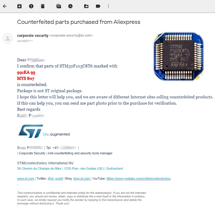
For several years now, the market has been flooded with counterfeit STM32F103 chips. The C8T6 and CBT6 variants (LQFP48) with 48 pins are the most affected. The counterfeits, usually relabeled as STM32, often contain an:
APM32F103
GD32F103
CKS32F103
HK32F103
CH32F103
CS32F103
BLM32F103
MM32F103
The following defects have been reported:
DMA controller hangs.
DMA controller triggers wrong interrupts.
OCN outputs of the timers do not work (affects PWM).
Timer 5 is missing.
I²C does not work.
USB does not work.
Debugging does not work.
Flashing only works via SWD, only via UART, or only at 115200 baud.
The chip ID can be read via firmware and mostly wrong or invalid (this is not possible with the original).
The defects mentioned only occur partially (never all together). The major problem is that you don’t know which ones you are being sold.
For more details read also:
 -- west flash: rebuilding
-- west flash: using runner pyocd
-- runners.pyocd: Flashing file: build/vccgnd_bluepill/zephyr/zephyr.hex
0001860 E Not a genuine ST Device! Abort connection. [functions]
0001905 I Loading build/vccgnd_bluepill/zephyr/zephyr.hex at 0x08000000 [load_cmd]
[==================================================] 100%
0004398 I Erased 32768 bytes (32 sectors), programmed 32768 bytes (32 pages), skipped 0 bytes (0 pages) at 12.96 kB/s [loader]
-- west flash: rebuilding
-- west flash: using runner pyocd
-- runners.pyocd: Flashing file: build/vccgnd_bluepill/zephyr/zephyr.hex
0001860 E Not a genuine ST Device! Abort connection. [functions]
0001905 I Loading build/vccgnd_bluepill/zephyr/zephyr.hex at 0x08000000 [load_cmd]
[==================================================] 100%
0004398 I Erased 32768 bytes (32 sectors), programmed 32768 bytes (32 pages), skipped 0 bytes (0 pages) at 12.96 kB/s [loader]
Supported Boards
Hardware
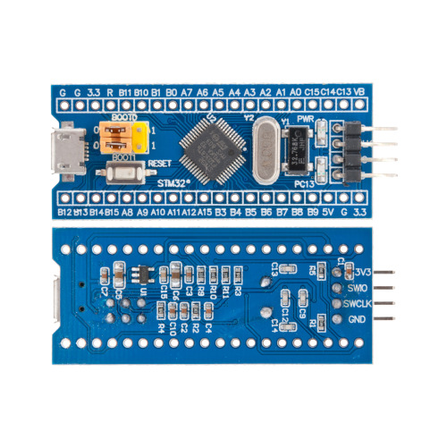
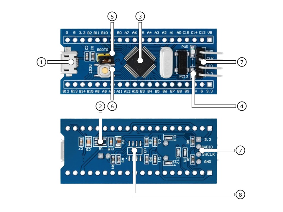
The VccGND Studio BluePill-STM32F1 [2] is available with an STM32F103 in two different configurations featuring different sizes of on-chip flash memory. It follows the general BluePill connector concept with two opposing 20-pin headers.
Features and Resources |
Printed Circuit Board |
5V/480㎃ 3.3V/300㎃ 3.3V(OUT) 72㎒ 64/128㎆ 16/20㎅ RST GREEN USB-B SWD 5 3 10 2 1 1 1
Design Data Remarks
|
|
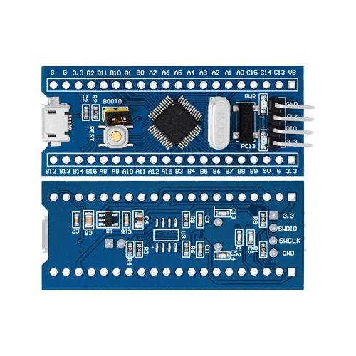
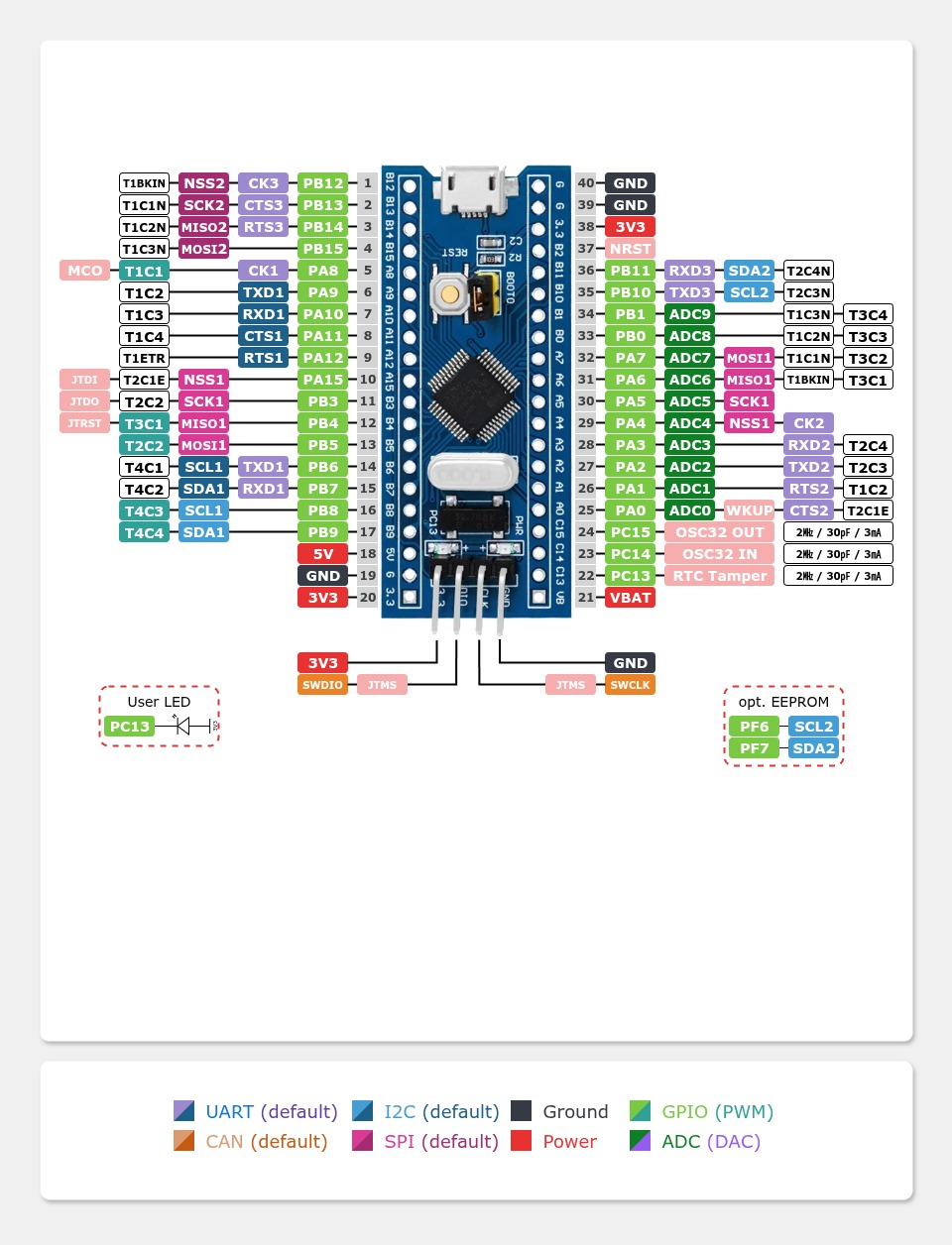
The VccGND Studio BluePill-STM32F0 [5] is available with an STM32F0 of the types F051 or F030 It follows the general BluePill connector concept with two opposing 20-pin connectors. The underlying schematic of the VccGND Studio BluePill-STM32F0 is similar to the original VccGND Studio BluePill-STM32F1 and offers with the two supported types F051 or F030 an additional EEPROM (unpopulated). This can be mounted onto the bottom of the board at position U3 as a SOP8 package. It is connected via the second I2C bus but pins PF6 and PF7 and not, as on the BluePill header, PB10 and PB11. CAN and USB is not available, but the USB-B micro connector is using for standard power supply.
Features and Resources |
Printed Circuit Board |
5V/480㎃ 3.3V/300㎃ 3.3V(OUT) 48㎒ 64㎆ 8㎅ RST RED USB-B SWD 7 5 10 2 1 1
Design Data Remarks
|
|
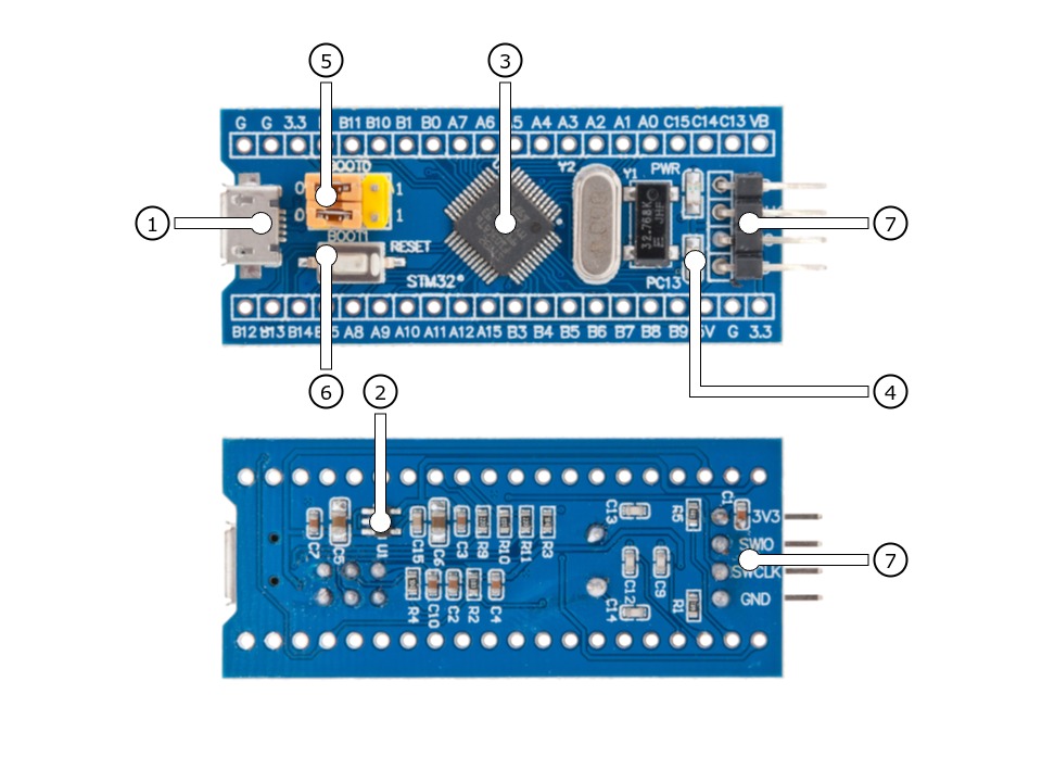
Positions
|
|---|
|
Data Sheets
|
|---|
|
Data Sheets
Pinouts
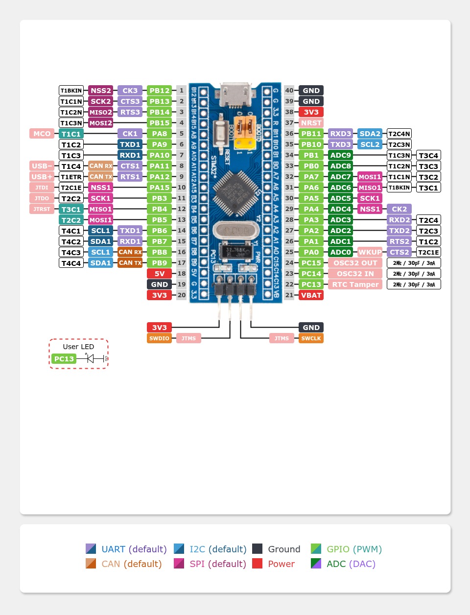
The peripherals of the different populated microcontrollers can be routed to various pins on the boards edge connectors. The configuration of these routes can be modified through DTS. Please refer to the datasheets to see the possible routings for each peripheral. The default assignment is defined below in a single table.
Pin Mapping |
Pinout |
Default Zephyr Peripheral Mapping
On-Board Mapping for SWD
On-Board Mapping for USER
Devicetree compatible |
|
Pin Mapping |
Pinout |
Default Zephyr Peripheral Mapping
On-Board Mapping for SWD
On-Board Mapping for USER
On-Board Routings for I2C EEPROM (unpopulated)
Devicetree compatible |
|
Supported Features
The VccGND BluePill board configuration supports the following Zephyr hardware features:
Peripheral |
Kconfig option |
Devicetree compatible |
Zephyr API |
|---|---|---|---|
PINCTRL |
|||
GPIO |
|||
UART |
|||
UDC (USB Device Controller) |
|||
CAN (L1: PMA / PCS, L2: DLL) |
|||
I2C |
|||
SPI |
|||
PWM |
|||
ADC |
|||
RTC |
|||
Timer (Counter) |
|||
Watchdog Timer (WDT) |
|||
Flash |
|||
DMA |
|||
HWINFO |
N/A |
||
RESET |
|||
CLOCK |
|||
NVIC |
N/A |
Nested Vector Interrupts Controller |
|
SYSTICK |
N/A |
Other hardware features are not currently supported by Zephyr. The default configuration can be found in the different Kconfig files:
Board Configurations
The VccGND BluePill boards can be configured for the following different use cases.
west build -b vccgnd_bluepill_stm32f103cb
Use the serial port USART1 on edge header as Zephyr console and for the shell.
west build -b vccgnd_bluepill_stm32f103cb -S usb-console
Use the native USB device port with CDC-ACM as Zephyr console and for the shell.
west build -b vccgnd_bluepill_stm32f103c8
Use the serial port USART1 on edge header as Zephyr console and for the shell.
west build -b vccgnd_bluepill_stm32f103c8 -S usb-console
Use the native USB device port with CDC-ACM as Zephyr console and for the shell.
west build -b vccgnd_bluepill_stm32f072cb
Use the serial port USART1 on edge header as Zephyr console and for the shell.
west build -b vccgnd_bluepill_stm32f072cb -S usb-console
Use the native USB device port with CDC-ACM as Zephyr console and for the shell.
west build -b vccgnd_bluepill_stm32f072c8
Use the serial port USART1 on edge header as Zephyr console and for the shell.
west build -b vccgnd_bluepill_stm32f072c8 -S usb-console
Use the native USB device port with CDC-ACM as Zephyr console and for the shell.
west build -b vccgnd_bluepill_stm32f051c8
Use the serial port USART1 on edge header as Zephyr console and for the shell.
west build -b vccgnd_bluepill_stm32f030c8
Use the serial port USART1 on edge header as Zephyr console and for the shell.
System and Real-Time Clock
The STM32 system clock (SYSCLK) on the VccGND BluePill boards can be driven by an internal or external oscillator, as well as the main PLL clock. By default the system clock is provided by the PLL clock with 72㎒ on STM32F1 or 48㎒ on STM32F0, which is driven by the external (on-board) 25㎒ crystal connected to the high-speed clock input.
The STM32 real-time clock (RTC) on the VccGND BluePill boards can be driven by an internal or external oscillator. By default, the real-time clock will be driven by the external (on-board) 32.768㎑ crystal connected to the low-speed clock input.
User LED
The VccGND BluePill boards feature one LED for user purposes at GPIO port C line 13 (PC13). The LED is low active.
ADC/TS Ports
The VccGND BluePill boards features an 12-bit ADC with 10 external usable channels and, when supported, some additional channels connected internaly to the on-chip temperature sensor (TS), the internal provided voltage reference source (VREF) and the external battery voltage (VBAT) when supported. The ADC channels 0-9 are available on the edge connectors.
SPI Port
The VccGND BluePill boards features one five wire SPI bus over SPI2 also available on the edge connectors and the standard pins. SPI1 is not available in any default setup.
I2C Port
The VccGND BluePill boards features two I2C buses over at I2C1 and I2C2 also available on the edge connectors and the standard pins. I2C1 is the BluePill standard bus.
CAN Port
The VccGND BluePill boards with STM32F1 and STM32F072 features one CAN controller, but without any CAN transceiver on board. The bus timing is defined by the DTS and is preset to 1000 kBit/s. The calculation was verified with the help of the CAN Bit Time Calculation Sheet [1] and can also assume smaller bit rates according to the following table. Note that the value of Prescaler, Seg 1 and Seg 2 will be calculated on demand by the Zephyr CAN Controller API together with the driver.
Bit Rate |
Sample Point at |
Prescaler |
Seg 1 ( |
Seg 2 ( |
|---|---|---|---|---|
1000 kBit/s |
88.9 % |
2 |
15 |
2 |
800 kBit/s |
88.9 % |
5 |
7 |
1 |
500 kBit/s |
88.9 % |
4 |
15 |
2 |
250 kBit/s |
88.9 % |
8 |
15 |
2 |
125 kBit/s |
88.9 % |
16 |
15 |
2 |
100 kBit/s |
88.9 % |
20 |
15 |
2 |
50 kBit/s |
88.9 % |
40 |
15 |
2 |
20 kBit/s |
88.9 % |
100 |
15 |
2 |
10 kBit/s |
88.9 % |
200 |
15 |
2 |
Bit Rate |
Sample Point at |
Prescaler |
Seg 1 ( |
Seg 2 ( |
|---|---|---|---|---|
1000 kBit/s |
87.5 % |
3 |
13 |
2 |
800 kBit/s |
86.7 % |
4 |
12 |
2 |
500 kBit/s |
87.5 % |
6 |
13 |
2 |
250 kBit/s |
87.5 % |
12 |
13 |
2 |
125 kBit/s |
87.5 % |
24 |
13 |
2 |
100 kBit/s |
87.5 % |
30 |
13 |
2 |
50 kBit/s |
87.5 % |
60 |
13 |
2 |
20 kBit/s |
87.5 % |
150 |
13 |
2 |
10 kBit/s |
87.5 % |
300 |
13 |
2 |
Serial Port
The VccGND BluePill boards feature one two wire UART (RxD/TxD) at USART1 and the standard pins (PA9/PA10) to be compatible with the STMicro on-chip bootloader for firmware downloads over UART. The Zephyr console output is assigned to this USART with the default settings of 115200/8N1 without any flow control (no XON/XOFF, no RTS/CTS).
USB Device Port
The VccGND BluePill boards with STM32F1 and STM32F072 features one (native) USB full-speed device port that can be used to communicate with a host PC. See the USB device support sample applications for more, such as the USB CDC-ACM sample which sets up a virtual serial port that echos characters back to the host PC. This boards provide the Zephyr console per default on the USB port as CDC ACM:
USB device idVendor=0483, idProduct=5740, bcdDevice= 4.02
USB device strings: Mfr=1, Product=2, SerialNumber=3
Product: BluePill STM32F103 (CDC ACM)
Manufacturer: VccGND (STMicroelectronics)
SerialNumber: 93F49F68D18508F0
USB device idVendor=0483, idProduct=5740, bcdDevice= 4.02
USB device strings: Mfr=1, Product=2, SerialNumber=3
Product: BluePill STM32F072 (CDC ACM)
Manufacturer: VccGND (STMicroelectronics)
SerialNumber: 8255970716DB9402
Programming and Debugging
Applications for the VccGND BluePill board configuration can be built and flashed in the usual Zephyr way (see Building an Application and Run an Application for more details).
Flashing
The VccGND BluePill board needs an debug tool adapter, e.g. ST-LINK/V2, SEGGER JLink, Arm CMSIS-DAP or similar.
Flashing an application
Here is an example for the Hello World application.
Run a serial host program to connect with your VccGND BluePill board:
user@host:~$ screen /dev/ttyUSBx 115200,cs8,parenb,-parodd,-cstopb,-crtscts
Build and flash the application:
west build -b vccgnd_bluepill_stm32f103c8 -p -d build/vccgnd_bluepill zephyr/samples/hello_world
west flash -r pyocd -d build/vccgnd_bluepill
You should see the following message on the console:
*** Booting Zephyr OS build v4.2.2 ***
Hello World! vccgnd_bluepill_stm32f103c8
Debugging
The SWD interface can also be used to debug the board. To achieve this, you can either use SEGGER JLink, OpenOCD or PyOCD.
You can debug an application in the usual way. Here is an example for the Hello World application:
west build -b vccgnd_bluepill_stm32f103c8 -p -d build/vccgnd_bluepill zephyr/samples/hello_world
west debug -r pyocd -d build/vccgnd_bluepill
Tests and Examples
LED Blinky with USB-CDC/ACM Console
west build -b vccgnd_bluepill_stm32f103cb -p -S usb-console -d build/vccgnd_bluepill zephyr/samples/basic/blinky
west flash -r pyocd -d build/vccgnd_bluepill
west build -b vccgnd_bluepill_stm32f103c8 -p -S usb-console -d build/vccgnd_bluepill zephyr/samples/basic/blinky
west flash -r pyocd -d build/vccgnd_bluepill
west build -b vccgnd_bluepill_stm32f072cb -p -S usb-console -d build/vccgnd_bluepill zephyr/samples/basic/blinky
west flash -r pyocd -d build/vccgnd_bluepill
west build -b vccgnd_bluepill_stm32f072c8 -p -S usb-console -d build/vccgnd_bluepill zephyr/samples/basic/blinky
west flash -r pyocd -d build/vccgnd_bluepill
Hello Shell
west build -b vccgnd_bluepill_stm32f103cb -p -d build/vccgnd_bluepill bridle/samples/helloshell -- \
-DEXTRA_CONF_FILE="prj-hwstartup.conf" -DCONFIG_STM32_ENABLE_DEBUG_SLEEP_STOP=y
west flash -r pyocd -d build/vccgnd_bluepill
memory consumption
[181/181] Linking C executable zephyr/zephyr.elf
Memory region         Used Size  Region Size  %age Used
           FLASH:       56148 B       128 KB     42.84%
             RAM:       18184 B        20 KB     88.79%
        IDT_LIST:          0 GB        32 KB      0.00%
west build -b vccgnd_bluepill_stm32f103c8 -p -d build/vccgnd_bluepill bridle/samples/helloshell -- \
-DEXTRA_CONF_FILE="prj-hwstartup.conf" -DCONFIG_STM32_ENABLE_DEBUG_SLEEP_STOP=y
west flash -r pyocd -d build/vccgnd_bluepill
memory consumption
[181/181] Linking C executable zephyr/zephyr.elf
Memory region         Used Size  Region Size  %age Used
           FLASH:       56148 B        64 KB     85.68%
             RAM:       18184 B        20 KB     88.79%
        IDT_LIST:          0 GB        32 KB      0.00%
west build -b vccgnd_bluepill_stm32f072cb -p -d build/vccgnd_bluepill bridle/samples/helloshell -- \
-DEXTRA_CONF_FILE="prj-minimal.conf" -DCONFIG_STM32_ENABLE_DEBUG_SLEEP_STOP=y \
-DCONFIG_ADC=y -DCONFIG_ADC_SHELL=y -DCONFIG_I2C=y -DCONFIG_I2C_SHELL=y
west flash -r pyocd -d build/vccgnd_bluepill
memory consumption
[159/159] Linking C executable zephyr/zephyr.elf
Memory region         Used Size  Region Size  %age Used
           FLASH:       37640 B       128 KB     28.72%
             RAM:        8912 B        16 KB     54.39%
        IDT_LIST:          0 GB        32 KB      0.00%
west build -b vccgnd_bluepill_stm32f072c8 -p -d build/vccgnd_bluepill bridle/samples/helloshell -- \
-DEXTRA_CONF_FILE="prj-minimal.conf" -DCONFIG_STM32_ENABLE_DEBUG_SLEEP_STOP=y \
-DCONFIG_ADC=y -DCONFIG_ADC_SHELL=y -DCONFIG_I2C=y -DCONFIG_I2C_SHELL=y
west flash -r pyocd -d build/vccgnd_bluepill
memory consumption
[159/159] Linking C executable zephyr/zephyr.elf
Memory region         Used Size  Region Size  %age Used
           FLASH:       37640 B        64 KB     57.43%
             RAM:        8912 B        16 KB     54.39%
        IDT_LIST:          0 GB        32 KB      0.00%
west build -b vccgnd_bluepill_stm32f051c8 -p -d build/vccgnd_bluepill bridle/samples/helloshell -- \
-DEXTRA_CONF_FILE="prj-tiny.conf" -DCONFIG_STM32_ENABLE_DEBUG_SLEEP_STOP=y \
-DCONFIG_ADC=y -DCONFIG_ADC_SHELL=y -DCONFIG_I2C=y -DCONFIG_I2C_SHELL=y
west flash -r pyocd -d build/vccgnd_bluepill
memory consumption
[159/159] Linking C executable zephyr/zephyr.elf
Memory region         Used Size  Region Size  %age Used
           FLASH:       34008 B        64 KB     51.89%
             RAM:        8112 B         8 KB     99.02%
        IDT_LIST:          0 GB        32 KB      0.00%
west build -b vccgnd_bluepill_stm32f030c8 -p -d build/vccgnd_bluepill bridle/samples/helloshell -- \
-DEXTRA_CONF_FILE="prj-tiny.conf" -DCONFIG_STM32_ENABLE_DEBUG_SLEEP_STOP=y \
-DCONFIG_ADC=y -DCONFIG_ADC_SHELL=y -DCONFIG_I2C=y -DCONFIG_I2C_SHELL=y
west flash -r pyocd -d build/vccgnd_bluepill
memory consumption
[159/159] Linking C executable zephyr/zephyr.elf
Memory region         Used Size  Region Size  %age Used
           FLASH:       33776 B        64 KB     51.54%
             RAM:        8104 B         8 KB     98.93%
        IDT_LIST:          0 GB        32 KB      0.00%