WeAct BluePill+
The WeAct Blue Pill Plus board is available in different versions, each with a specific microcontroller from different silicon vendors in standard package size LQFP48. It is a clone of the original hobbyist Blue Pill board solderd with either STM32F0 [54] or STM32F1 [55] microcontrollers. Partially, Zephyr upstream boards also exist. See the Links / References column below.
Architecture |
Vendor |
MCU Series / Line / Type |
Clock |
Flash |
SRAM |
Status |
Links / References |
||
|---|---|---|---|---|---|---|---|---|---|
Arm Cortex-M4 |
120㎒ |
256㎅ |
48㎅ |
❌ |
|||||
Arm Cortex-M3 |
72㎒ |
128㎅ |
20㎅ |
✅ |
|||||
72㎒ |
64㎅ |
20㎅ |
|||||||
96㎒ |
128㎅ |
20㎅ |
❌ |
||||||
96㎒ |
64㎅ |
20㎅ |
|||||||
108㎒ |
128㎅ |
20㎅ |
|||||||
108㎒ |
64㎅ |
20㎅ |
|||||||
72㎒ |
64㎅ |
20㎅ |
|||||||
72㎒ |
32㎅ |
10㎅ |
|||||||
RISC-V QingKe V3A |
80㎒ |
64㎅ |
20㎅ |
||||||
80㎒ |
32㎅ |
10㎅ |
|||||||
RISC-V QingKe V4B |
144㎒ |
64㎅ |
20㎅ |
⚠️ |
|||||
144㎒ |
32㎅ |
10㎅ |
|||||||
- ✅ :
fully supported, no known issues
STM32F103CB:
weact_bluepillplus_stm32f103cbSTM32F103C8:
weact_bluepillplus_stm32f103c8
- ⚠️ :
not yet completed, as full SoC driver support is missing:
CH32V203C8:
weact_bluepillplus_ch32v203c8CH32V203C6:
weact_bluepillplus_ch32v203c6
- ❌ :
not yet supported, as SoC support is missing:
GD32F303CC:
weact_bluepillplus_gd32f303ccAPM32F103CB:
weact_bluepillplus_apm32f103cbAPM32F103C8:
weact_bluepillplus_apm32f103c8GD32F103CB:
weact_bluepillplus_gd32f103cbGD32F103C8:
weact_bluepillplus_gd32f103c8CH32F103C8:
weact_bluepillplus_ch32f103c8CH32F103C6:
weact_bluepillplus_ch32f103c6CH32V103C8:
weact_bluepillplus_ch32v103c8CH32V103C6:
weact_bluepillplus_ch32v103c6
Supported Boards
Hardware
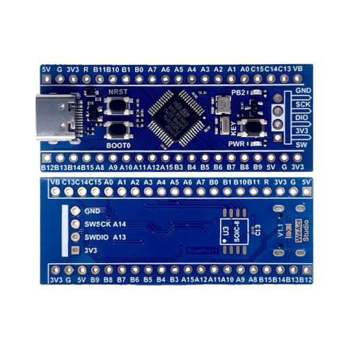
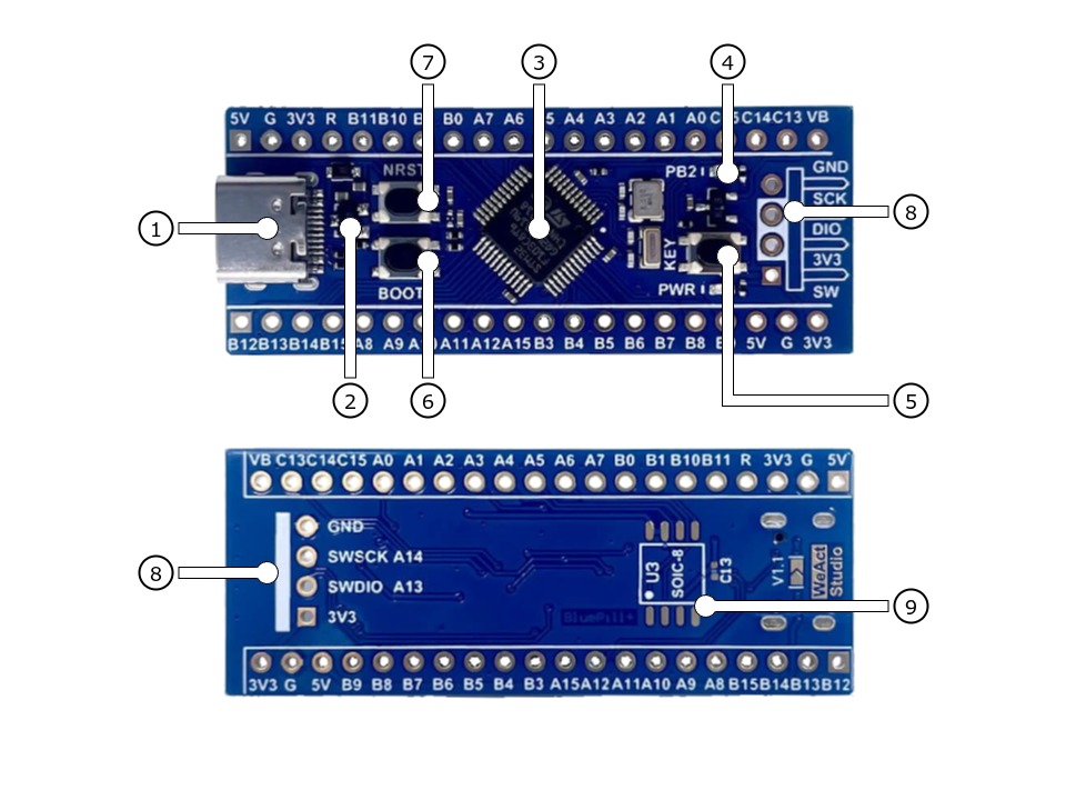
The WeAct Studio BluePill-Plus [10] is available with an STM32F103 in two different configurations featuring different sizes of on-chip flash memory. It follows the general BluePill connector concept with two opposing 20-pin headers. The underlying schematic diagram also provides an additional SPI flash (unpopulated). This can be mounted on the bottom of the board at position U3 as an SOIC8 package. It is connected via the first SPI bus, but through pins PA4 to PA7, and thus conflicts with ADC channels 4 to 7, which are located on the same pins as on the BluePill header.
Features and Resources |
Printed Circuit Board |
5V/480㎃ 3.3V/300㎃ 3.3V(OUT) 72㎒ 64/128㎆ 20㎅ RST BOOT USER BLUE USB-C SWD 5 3 10 2 1 1 1
Design Data Remarks
|
|
The WeAct Studio BluePill-Plus-CH32 [15] is available with an CH32V203 in two different configurations featuring different sizes of on-chip flash memory. It follows the general BluePill connector concept with two opposing 20-pin headers. The underlying schematic diagram also provides an additional SPI flash (unpopulated). This can be mounted on the bottom of the board at position U3 as an SOIC8 package. It is connected via the first SPI bus, but through pins PA4 to PA7, and thus conflicts with ADC channels 4 to 7, which are located on the same pins as on the BluePill header.
Features and Resources |
Printed Circuit Board |
5V/480㎃ 3.3V/300㎃ 3.3V(OUT) 144㎒ 32/64㎆ 10/20㎅ RST BOOT USER BLUE USB-C SWD 5 3 10 2 1 1 1
Design Data Remarks
|
|
Positions
|
|---|
|
Data Sheets
|
|
|---|
|
Data Sheets
Pinouts
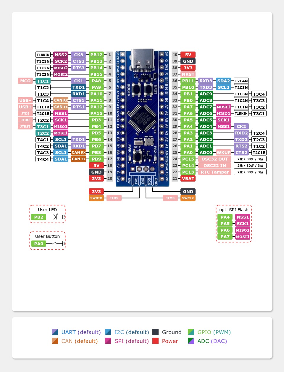
The peripherals of the different populated microcontrollers can be routed to various pins on the boards edge connectors. The configuration of these routes can be modified through DTS. Please refer to the datasheets to see the possible routings for each peripheral. The default assignment is defined below in a single table.
Pin Mapping |
Pinout |
Default Zephyr Peripheral Mapping
On-Board Mapping for SWD
On-Board Mapping for USER and USER
On-Board Routings for SPI Flash (unpopulated)
Devicetree compatible |
|
Pin Mapping |
Pinout |
Default Zephyr Peripheral Mapping
On-Board Mapping for SWD
On-Board Mapping for USER and USER
On-Board Routings for SPI Flash (unpopulated)
Devicetree compatible |
|
Supported Features
The WeAct BluePill+ board configuration supports the following Zephyr hardware features:
Peripheral |
Kconfig option |
Devicetree compatible |
Zephyr API |
|---|---|---|---|
PINCTRL |
|||
GPIO |
|||
UART |
|||
UDC (USB Device Controller) |
|||
CAN (L1: PMA / PCS, L2: DLL) |
|||
I2C |
|||
SPI |
|||
PWM |
|||
ADC |
|||
RTC |
|||
Timer (Counter) |
|||
Watchdog Timer (WDT) |
|||
Flash |
|||
DMA |
|||
HWINFO |
N/A |
||
RESET |
st,stm32f1-rcc |
||
CLOCK |
|||
NVIC |
N/A |
Nested Vector Interrupts Controller |
|
SYSTICK |
N/A |
Other hardware features are not currently supported by Zephyr. The default configuration can be found in the different Kconfig files:
Peripheral |
Kconfig option |
Devicetree compatible |
Zephyr API |
|---|---|---|---|
PINCTRL |
|||
GPIO |
|||
UART |
|||
SPI |
|||
RESET |
|||
CLOCK |
|||
NVIC (PFIC) |
N/A |
Nested Vector Interrupts Controller |
|
SYSTICK |
N/A |
Other hardware features are not currently supported by Zephyr. The default configuration can be found in the different Kconfig files:
Board Configurations
The WeAct BluePill+ boards can be configured for the following different use cases.
west build -b weact_bluepillplus_stm32f103cb -S usb-console
Use the native USB device port with CDC-ACM as Zephyr console and for the shell.
west build -b weact_bluepillplus_stm32f103cb
Use the serial port USART1 on edge header as Zephyr console and for the shell.
west build -b weact_bluepillplus_stm32f103c8 -S usb-console
Use the native USB device port with CDC-ACM as Zephyr console and for the shell.
west build -b weact_bluepillplus_stm32f103c8
Use the serial port USART1 on edge header as Zephyr console and for the shell.
west build -b weact_bluepillplus_ch32v203c8
Use the serial port USART1 on edge header as Zephyr console and for the shell.
west build -b weact_bluepillplus_ch32v203c6
Use the serial port USART1 on edge header as Zephyr console and for the shell.
System and Real-Time Clock
The STM32 system clock (SYSCLK) on the WeAct BluePill+ boards can be driven by an internal or external oscillator, as well as the main PLL clock. By default the system clock is provided by the PLL clock with 72㎒ on STM32F1 or up to 144㎒ on the other counterfeited chips, which is driven by the external (on-board) 25㎒ crystal connected to the high-speed clock input.
The STM32 real-time clock (RTC) on the WeAct BluePill+ boards can be driven by an internal or external oscillator. By default, the real-time clock will be driven by the external (on-board) 32.768㎑ crystal connected to the low-speed clock input.
User LED
The WeAct BluePill+ boards feature one LED for user purposes at GPIO port B line 2 (PB2) in parallel to the BOOT1 signal. The LED is high active.
ADC/TS Ports
The WeAct BluePill+ boards features an 12-bit ADC with 10 external usable channels and, when supported, some additional channels connected internaly to the on-chip temperature sensor (TS), the internal provided voltage reference source (VREF) and the external battery voltage (VBAT) when supported. The ADC channels 0-9 are available on the edge connectors.
SPI Port
The WeAct BluePill+ boards features one five wire SPI bus over SPI2 also available on the edge connectors and the standard pins. SPI1 is not available in any default setup.
I2C Port
The WeAct BluePill+ boards features two I2C buses over at I2C1 and I2C2 also available on the edge connectors and the standard pins. I2C1 is the BluePill standard bus.
CAN Port
The WeAct BluePill+ boards with STM32F1 features one CAN controller, but without any CAN transceiver on board. The bus timing is defined by the DTS and is preset to 1000 kBit/s. The calculation was verified with the help of the CAN Bit Time Calculation Sheet [6] and can also assume smaller bit rates according to the following table. Note that the value of Prescaler, Seg 1 and Seg 2 will be calculated on demand by the Zephyr CAN Controller API together with the driver.
Bit Rate |
Sample Point at |
Prescaler |
Seg 1 ( |
Seg 2 ( |
|---|---|---|---|---|
1000 kBit/s |
88.9 % |
2 |
15 |
2 |
800 kBit/s |
88.9 % |
5 |
7 |
1 |
500 kBit/s |
88.9 % |
4 |
15 |
2 |
250 kBit/s |
88.9 % |
8 |
15 |
2 |
125 kBit/s |
88.9 % |
16 |
15 |
2 |
100 kBit/s |
88.9 % |
20 |
15 |
2 |
50 kBit/s |
88.9 % |
40 |
15 |
2 |
20 kBit/s |
88.9 % |
100 |
15 |
2 |
10 kBit/s |
88.9 % |
200 |
15 |
2 |
Bit Rate |
Sample Point at |
Prescaler |
Seg 1 ( |
Seg 2 ( |
|---|---|---|---|---|
1000 kBit/s |
88.9 % |
|||
800 kBit/s |
88.9 % |
|||
500 kBit/s |
88.9 % |
|||
250 kBit/s |
88.9 % |
|||
125 kBit/s |
88.9 % |
|||
100 kBit/s |
88.9 % |
|||
50 kBit/s |
88.9 % |
|||
20 kBit/s |
88.9 % |
|||
10 kBit/s |
88.9 % |
Not yet completed, as full SoC driver support is missing.
Serial Port
The WeAct BluePill+ boards feature one two wire UART (RxD/TxD) at USART1 and the standard pins (PA9/PA10) to be compatible with the STMicro on-chip bootloader for firmware downloads over UART. The Zephyr console output is assigned to this USART with the default settings of 115200/8N1 without any flow control (no XON/XOFF, no RTS/CTS).
USB Device Port
The WeAct BluePill+ boards with STM32F1 features one (native) USB full-speed device port that can be used to communicate with a host PC. See the USB sample applications for more, such as the USB CDC ACM UART sample sample which sets up a virtual serial port that echos characters back to the host PC. This boards provide the Zephyr console per default on the USB port as CDC ACM:
USB device idVendor=0483, idProduct=5740, bcdDevice= 4.03
USB device strings: Mfr=1, Product=2, SerialNumber=3
Product: BluePill+ STM32F103 (CDC ACM)
Manufacturer: WeAct (STMicroelectronics)
SerialNumber: 93F49F68D18508F0
USB device idVendor=0483, idProduct=5740, bcdDevice= 4.03
USB device strings: Mfr=1, Product=2, SerialNumber=3
Product: BluePill+ CH32V203 (CDC ACM)
Manufacturer: WeAct (STMicroelectronics)
SerialNumber: 862EE3CD7085708E
Not yet completed, as full SoC driver support is missing.
Programming and Debugging
Applications for the WeAct BluePill+ board configuration can be built and flashed in the usual Zephyr way (see Building an Application and Run an Application for more details).
Flashing
The WeAct BluePill+ board needs an debug tool adapter, e.g. ST-LINK/V2, SEGGER JLink, Arm CMSIS-DAP or similar.
Flashing an application
Here is an example for the Hello World application.
Run a serial host program to connect with your WeAct BluePill+ board:
user@host:~$ screen /dev/ttyUSBx 115200,cs8,parenb,-parodd,-cstopb,-crtscts
Build and flash the application:
west build -b weact_bluepillplus_stm32f103c8 -p -d build/weact_bluepillplus zephyr/samples/hello_world
west flash -r openocd -d build/weact_bluepillplus
You should see the following message on the console:
*** Booting Zephyr OS build v4.3.0…***
Hello World! weact_bluepillplus_stm32f103c8
Debugging
The SWD interface can also be used to debug the board. To achieve this, you can either use SEGGER JLink, OpenOCD or PyOCD.
You can debug an application in the usual way. Here is an example for the Hello World application:
west build -b weact_bluepillplus_stm32f103c8 -p -d build/weact_bluepillplus zephyr/samples/hello_world
west debug -r openocd -d build/weact_bluepillplus
Tests and Examples
LED Blinky with USB-CDC/ACM Console
west build -b weact_bluepillplus_stm32f103cb -p -S "usb-console" -d build/weact_bluepillplus zephyr/samples/basic/blinky
west flash -r openocd -d build/weact_bluepillplus
memory consumption
[174/174] Linking C executable zephyr/zephyr.elf
Memory region         Used Size  Region Size  %age Used
           FLASH:       45000 B       128 KB     34.33%
             RAM:       14648 B        20 KB     71.52%
           SRAM0:          0 GB        20 KB      0.00%
        IDT_LIST:          0 GB        32 KB      0.00%
west build -b weact_bluepillplus_stm32f103c8 -p -S "usb-console" -d build/weact_bluepillplus zephyr/samples/basic/blinky
west flash -r openocd -d build/weact_bluepillplus
memory consumption
[174/174] Linking C executable zephyr/zephyr.elf
Memory region         Used Size  Region Size  %age Used
           FLASH:       45000 B        64 KB     68.66%
             RAM:       14648 B        20 KB     71.52%
           SRAM0:          0 GB        20 KB      0.00%
        IDT_LIST:          0 GB        32 KB      0.00%
Note
USB not yet supported on CH32V2, using UART Console instead!
Note: Please refer to the section Installing optional WCH-Link tools. Either minichlink or openocd with WCH-Link support is required for programming the CH32V microcontrollers.
west build -b weact_bluepillplus_ch32v203c8 -p -d build/weact_bluepillplus zephyr/samples/basic/blinky
west flash -r minichlink -d build/weact_bluepillplus
memory consumption
[126/126] Linking C executable zephyr/zephyr.elf
Memory region         Used Size  Region Size  %age Used
             ROM:       12960 B        64 KB     19.78%
             RAM:        4224 B        20 KB     20.62%
        IDT_LIST:          0 GB         4 KB      0.00%
Note: Please refer to the section Installing optional WCH-Link tools. Either minichlink or openocd with WCH-Link support is required for programming the CH32V microcontrollers.
west build -b weact_bluepillplus_ch32v203c6 -p -d build/weact_bluepillplus zephyr/samples/basic/blinky
west flash -r minichlink -d build/weact_bluepillplus
memory consumption
[126/126] Linking C executable zephyr/zephyr.elf
Memory region         Used Size  Region Size  %age Used
             ROM:       12964 B        32 KB     39.56%
             RAM:        4224 B        10 KB     41.25%
        IDT_LIST:          0 GB         4 KB      0.00%
Hello Shell
west build -b weact_bluepillplus_stm32f103cb -p -d build/weact_bluepillplus bridle/samples/helloshell -- \
-DEXTRA_CONF_FILE="prj-hwstartup.conf" -DCONFIG_STM32_ENABLE_DEBUG_SLEEP_STOP=y
west flash -r openocd -d build/weact_bluepillplus
memory consumption
[185/185] Linking C executable zephyr/zephyr.elf
Memory region         Used Size  Region Size  %age Used
           FLASH:       57264 B       128 KB     43.69%
             RAM:       16840 B        20 KB     82.23%
           SRAM0:          0 GB        20 KB      0.00%
        IDT_LIST:          0 GB        32 KB      0.00%
west build -b weact_bluepillplus_stm32f103c8 -p -d build/weact_bluepillplus bridle/samples/helloshell -- \
-DEXTRA_CONF_FILE="prj-hwstartup.conf" -DCONFIG_STM32_ENABLE_DEBUG_SLEEP_STOP=y
west flash -r openocd -d build/weact_bluepillplus
memory consumption
[185/185] Linking C executable zephyr/zephyr.elf
Memory region         Used Size  Region Size  %age Used
           FLASH:       57264 B        64 KB     87.38%
             RAM:       16840 B        20 KB     82.23%
           SRAM0:          0 GB        20 KB      0.00%
        IDT_LIST:          0 GB        32 KB      0.00%
Note: Please refer to the section Installing optional WCH-Link tools. Either minichlink or openocd with WCH-Link support is required for programming the CH32V microcontrollers.
west build -b weact_bluepillplus_ch32v203c8 -p -d build/weact_bluepillplus bridle/samples/helloshell -- \
-DEXTRA_CONF_FILE="prj-hwstartup.conf" -DCONFIG_FLASH=n -DCONFIG_FLASH_SHELL=n
west flash -r minichlink -d build/weact_bluepillplus
memory consumption
[152/152] Linking C executable zephyr/zephyr.elf
Memory region         Used Size  Region Size  %age Used
             ROM:       47528 B        64 KB     72.52%
             RAM:        8064 B        20 KB     39.38%
        IDT_LIST:          0 GB         4 KB      0.00%
Note: Please refer to the section Installing optional WCH-Link tools. Either minichlink or openocd with WCH-Link support is required for programming the CH32V microcontrollers.
west build -b weact_bluepillplus_ch32v203c6 -p -d build/weact_bluepillplus bridle/samples/helloshell -- -DEXTRA_CONF_FILE="prj-minimal.conf"
west flash -r minichlink -d build/weact_bluepillplus
memory consumption
[135/135] Linking C executable zephyr/zephyr.elf
Memory region         Used Size  Region Size  %age Used
             ROM:       22596 B        32 KB     68.96%
             RAM:        7136 B        10 KB     69.69%
        IDT_LIST:          0 GB         4 KB      0.00%