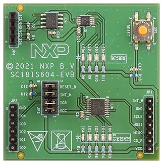
NXP SC18IS604-EVB
1 1 5 4 9 1 (RESET)
The NXP [9] SC18IS604-EVB [10] is an evaluation kit for the SC18IS604 [16] chip, an SPI to I2C bus bridge with an integrated GPIO controller. Apart from the bridge it features:
5 LED connected to the GPIO pins
1 PCA9533 [14], an 4-bit PWM controller connected to the outgoing I2C bus which controls:
4 additional dimmable LEDs
1 24LC02B [18] 256×8-bit EEPROM, also connected to the outgoing I2C bus
Note
There is currently no device driver support for the PCA9533 LED dimmer, either in Zephyr or in Bridle. Therefore, this shield will not set up the 4-bit PWM controller; the additional dimmable LEDs cannot be used by application code.
Design Data
Data Sheets
Utilization
The shield abstraction of these breakout boards is deliberately kept small. It is purely for evaluating the necessary drivers and Devicetree bindings on known integration platforms.
Since the shield does not use a standard plug-on design, it must be manually
wired to the correct signals on the host board. This wiring is represented by
an additional shield, depending on the signal routing. This shields can be
used with any development board or shield that provides a Devicetree node with
the nxp,sc18is604-evb-hif-header property in the compatibility.
That is needed for GPIO mapping of the reset and interrupt line. Users can rely
on the NXP SC18IS604-EVB Interconnection Shield or create their own interconnection
shields with the necessary mappings in them.
Programming
If the host board has an Arduino UNO R3 connector available, its signals can
be used to connect the shield. The NXP SC18IS604-EVB Interconnection Shield contains
already the required signal definitions for this configuration. To use this (or
another) connector shield, include it in the shield list for your build:
west build -b <your_board> --shield "x_nxp_sc18is604_evb;nxp_sc18is604_evb" <your-application>
Hello Shell on Nucleo F746ZG
Set --shield x_nxp_sc18is604_evb;nxp_sc18is604_evb when you invoke
west build or -DSHIELD=x_nxp_sc18is604_evb;nxp_sc18is604_evb for
cmake. For example:
west build -b nucleo_f746zg -p --shield "x_nxp_sc18is604_evb nxp_sc18is604_evb" -d build/nxp_sc18is604_evb bridle/samples/helloshell
west flash -d build/nxp_sc18is604_evb
boot logging output
Simple test execution on target
(text in bold is a command input)
uart:~$ hello -h
hello - say hello
uart:~$ hello
Hello from shell.
uart:~$ hwinfo devid
Length: 8
ID: 0x8c998be1de969148

uart:~$ kernel version
Zephyr version 4.3.0

uart:~$ bridle version
Bridle version 4.3.0

uart:~$ bridle version long
Bridle version 4.3.0.0

uart:~$ bridle info
Zephyr: 4.3.0
Bridle: 4.3.0
uart:~$ device list
devices:
- rcc@40023800 (READY)
  DT node labels: rcc
- reset-controller (READY)
  DT node labels: rctl
- interrupt-controller@40013c00 (READY)
  DT node labels: exti
- gpio@40022800 (READY)
  DT node labels: gpiok
- gpio@40022400 (READY)
  DT node labels: gpioj
- gpio@40022000 (READY)
  DT node labels: gpioi
- gpio@40021C00 (READY)
  DT node labels: gpioh
- gpio@40021800 (READY)
  DT node labels: gpiog
- gpio@40021400 (READY)
  DT node labels: gpiof
- gpio@40021000 (READY)
  DT node labels: gpioe
- gpio@40020C00 (READY)
  DT node labels: gpiod
- gpio@40020800 (READY)
  DT node labels: gpioc
- gpio@40020400 (READY)
  DT node labels: gpiob
- gpio@40020000 (READY)
  DT node labels: gpioa
- serial@40011400 (READY)
  DT node labels: usart6 arduino_serial
- serial@40004800 (READY)
  DT node labels: usart3
- adc@40012000 (READY)
  DT node labels: adc1
- dac@40007400 (READY)
  DT node labels: dac1
- flash-controller@40023c00 (READY)
  DT node labels: flash
- i2c@40005800 (READY)
  DT node labels: i2c2
- i2c@40005400 (READY)
  DT node labels: i2c1 arduino_i2c
- pwm (READY)
  DT node labels: pwm1
- spi@40013000 (READY)
  DT node labels: spi1 arduino_spi nxp_sc18is604_evb_spi
- sc18is604@0 (READY)
  DT node labels: sc18is604_0
- sc18is604-0-i2c (READY)
  DT node labels: sc18is604_0_i2c nxp_sc18is604_evb_i2c
- sc18is604-0-eeprom@50 (READY)
  DT node labels: nxp_sc18is604_evb_eeprom
- sc18is604-0-gpio (READY)
  DT node labels: sc18is604_0_gpio
- memory@40024000 (READY)
  DT node labels: backup_sram
- sc18is604-0-gpio-leds (READY)
  DT node labels: nxp_sc18is604_evb_gpio_leds
- leds (READY)
  DT node labels: leds
- dietemp (READY)
  DT node labels: die_temp
- vbat (READY)
  DT node labels: vbat
- vref (READY)
  DT node labels: vref
uart:~$ history
[  0] history
[  1] device list
[  2] bridle info
[  3] bridle version long
[  4] bridle version
[  5] kernel version
[  6] hwinfo devid
[  7] hello
[  8] hello -h
Operate with the on-shield LED D3 at IO2:
uart:~$ led on sc18is604-0-gpio-leds 2
sc18is604-0-gpio-leds: turning on LED 2
uart:~$ led off sc18is604-0-gpio-leds 2
sc18is604-0-gpio-leds: turning off LED 2
uart:~$ led set_brightness sc18is604-0-gpio-leds 2 100
sc18is604-0-gpio-leds: setting LED 2 brightness to 100
uart:~$ led set_brightness sc18is604-0-gpio-leds 2 10
sc18is604-0-gpio-leds: setting LED 2 brightness to 10
uart:~$ led set_brightness sc18is604-0-gpio-leds 2 0
sc18is604-0-gpio-leds: setting LED 2 brightness to 0
Operate with the on-shield LED D2 at IO1:
uart:~$ gpio get sc18is604-0-gpio 1
0

uart:~$ gpio conf sc18is604-0-gpio 1 ol0
uart:~$ gpio set sc18is604-0-gpio 1 1
uart:~$ gpio set sc18is604-0-gpio 1 0

uart:~$ gpio blink sc18is604-0-gpio 1
Hit any key to exit
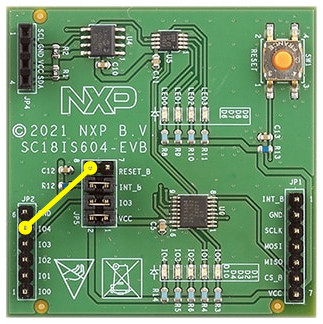
Operate with the abused on-shield RESET key SW1 at IO4 (see wiring beside):
uart:~$ gpio get sc18is604-0-gpio 4
1

uart:~$ gpio conf sc18is604-0-gpio 4 iul
uart:~$ gpio get sc18is604-0-gpio 4
0
uart:~$ gpio get sc18is604-0-gpio 4
1
uart:~$ gpio get sc18is604-0-gpio 4
0
Scan the on-shield I2C devices, the EEPROM and the 4-bit PWM controller:
uart:~$ i2c scan sc18is604-0-i2c
     0  1  2  3  4  5  6  7  8  9  a  b  c  d  e  f
00:             -- -- -- -- -- -- -- -- -- -- -- --
10: -- -- -- -- -- -- -- -- -- -- -- -- -- -- -- --
20: -- -- -- -- -- -- -- -- -- -- -- -- -- -- -- --
30: -- -- -- -- -- -- -- -- -- -- -- -- -- -- -- --
40: -- -- -- -- -- -- -- -- -- -- -- -- -- -- -- --
50: 50 51 52 53 54 55 56 57 -- -- -- -- -- -- -- --
60: -- -- 62 -- -- -- -- -- -- -- -- -- -- -- -- --
70: -- -- -- -- -- -- -- --
9 devices found on sc18is604-0-i2c
The I2C address 0x50 to 0x57 is the 256×8-bit EEPROM 24LC02B [18].
The I2C address 0x62 is the 4-bit PWM controller PCA9533 [14].
Operate with the on-shield 4-bit PWM controller on the new I2C bus, as described in the PCA9533 Datasheet [15]. Control the on-shield LED D6 at LED0:
uart:~$ i2c write_byte sc18is604-0-i2c 62 5 1
uart:~$ i2c write_byte sc18is604-0-i2c 62 5 2
uart:~$ i2c write_byte sc18is604-0-i2c 62 5 0
Operate with the on-shield 256×8-bit EEPROM (256 byte):
uart:~$ eeprom read sc18is604-0-eeprom@50 0 32
Reading 32 bytes from EEPROM, offset 0...
00000000: 11 02 03 04 23 42 ff ff  ff ff ff ff ff ff ff ff |....#B.. ........|
00000010: ff ff ff ff ff ff ff ff  ff ff ff ff ff ff ff ff |........ ........|
uart:~$ eeprom fill sc18is604-0-eeprom@50 0 256 0x5a
Writing 256 bytes of 0x5a to EEPROM...
Verifying...
Verify OK

uart:~$ eeprom read sc18is604-0-eeprom@50 0 256
Reading 256 bytes from EEPROM, offset 0...
00000000: 5a 5a 5a 5a 5a 5a 5a 5a  5a 5a 5a 5a 5a 5a 5a 5a |ZZZZZZZZ ZZZZZZZZ|
00000010: 5a 5a 5a 5a 5a 5a 5a 5a  5a 5a 5a 5a 5a 5a 5a 5a |ZZZZZZZZ ZZZZZZZZ|
00000020: 5a 5a 5a 5a 5a 5a 5a 5a  5a 5a 5a 5a 5a 5a 5a 5a |ZZZZZZZZ ZZZZZZZZ|
00000030: 5a 5a 5a 5a 5a 5a 5a 5a  5a 5a 5a 5a 5a 5a 5a 5a |ZZZZZZZZ ZZZZZZZZ|
00000040: 5a 5a 5a 5a 5a 5a 5a 5a  5a 5a 5a 5a 5a 5a 5a 5a |ZZZZZZZZ ZZZZZZZZ|
00000050: 5a 5a 5a 5a 5a 5a 5a 5a  5a 5a 5a 5a 5a 5a 5a 5a |ZZZZZZZZ ZZZZZZZZ|
00000060: 5a 5a 5a 5a 5a 5a 5a 5a  5a 5a 5a 5a 5a 5a 5a 5a |ZZZZZZZZ ZZZZZZZZ|
00000070: 5a 5a 5a 5a 5a 5a 5a 5a  5a 5a 5a 5a 5a 5a 5a 5a |ZZZZZZZZ ZZZZZZZZ|
00000080: 5a 5a 5a 5a 5a 5a 5a 5a  5a 5a 5a 5a 5a 5a 5a 5a |ZZZZZZZZ ZZZZZZZZ|
00000090: 5a 5a 5a 5a 5a 5a 5a 5a  5a 5a 5a 5a 5a 5a 5a 5a |ZZZZZZZZ ZZZZZZZZ|
000000A0: 5a 5a 5a 5a 5a 5a 5a 5a  5a 5a 5a 5a 5a 5a 5a 5a |ZZZZZZZZ ZZZZZZZZ|
000000B0: 5a 5a 5a 5a 5a 5a 5a 5a  5a 5a 5a 5a 5a 5a 5a 5a |ZZZZZZZZ ZZZZZZZZ|
000000C0: 5a 5a 5a 5a 5a 5a 5a 5a  5a 5a 5a 5a 5a 5a 5a 5a |ZZZZZZZZ ZZZZZZZZ|
000000D0: 5a 5a 5a 5a 5a 5a 5a 5a  5a 5a 5a 5a 5a 5a 5a 5a |ZZZZZZZZ ZZZZZZZZ|
000000E0: 5a 5a 5a 5a 5a 5a 5a 5a  5a 5a 5a 5a 5a 5a 5a 5a |ZZZZZZZZ ZZZZZZZZ|
000000F0: 5a 5a 5a 5a 5a 5a 5a 5a  5a 5a 5a 5a 5a 5a 5a 5a |ZZZZZZZZ ZZZZZZZZ|
uart:~$ eeprom fill sc18is604-0-eeprom@50 0 256 0xff
Writing 256 bytes of 0xff to EEPROM...
Verifying...
Verify OK

uart:~$ eeprom write sc18is604-0-eeprom@50 0 17 2 3 4 35 66
Writing 6 bytes to EEPROM...
Verifying...
Verify OK

uart:~$ eeprom read sc18is604-0-eeprom@50 0 32
Reading 32 bytes from EEPROM, offset 0...
00000000: 11 02 03 04 23 42 ff ff  ff ff ff ff ff ff ff ff |....#B.. ........|
00000010: ff ff ff ff ff ff ff ff  ff ff ff ff ff ff ff ff |........ ........|
More Samples and Tests
On-Shield LED Blinky by GPIO
See also Zephyr sample: Blinky.
west build -b nucleo_f746zg -p --shield "x_nxp_sc18is604_evb nxp_sc18is604_evb" -d build/nxp_sc18is604_evb zephyr/samples/basic/blinky
west flash -d build/nxp_sc18is604_evb
On-Shield LED Blinky by PWM
Do not use!
Not yet, because of missing PCA9533 device driver support.
See also Zephyr sample: PWM Blinky.
west build -b nucleo_f746zg -p --shield "x_nxp_sc18is604_evb nxp_sc18is604_evb" -d build/nxp_sc18is604_evb zephyr/samples/basic/blinky_pwm
west flash -d build/nxp_sc18is604_evb
On-Shield LED Fade by PWM
Do not use!
Not yet, because of missing PCA9533 device driver support.
See also Zephyr sample: Fade LED.
west build -b nucleo_f746zg -p --shield "x_nxp_sc18is604_evb nxp_sc18is604_evb" -d build/nxp_sc18is604_evb zephyr/samples/basic/fade_led
west flash -d build/nxp_sc18is604_evb
On-Shield EEPROM Read/Write
See also Zephyr sample: EEPROM.
west build -b nucleo_f746zg -p --shield "x_nxp_sc18is604_evb nxp_sc18is604_evb" -d build/nxp_sc18is604_evb zephyr/samples/drivers/eeprom
west flash -d build/nxp_sc18is604_evb