Seeeduino Cortex-M0+
Overview
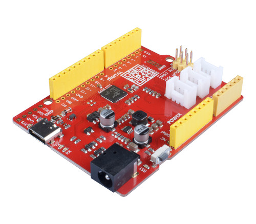
The Seeeduino Cortex-M0+ is an Arduino form factor development board based on
an Atmel SAMD21 ARM with onboard LEDs, USB-C port, and range of 14 digital I/O
(10 of which support PWM) and 6 analog I/O broken out onto Arduino UNO R3
header. It provides 3 on-board Grove connectors for I2C and UART.
Hardware
ATSAMD21G18A [10] ARM Cortex-M0+ processor at 48 MHz
32.768 kHz crystal oscillator
256 KiB flash memory and 32 KiB of RAM
3 user LEDs (blue/Rx/Tx)
One reset button
Native USB-C port (supply power and transmit data)
Arduino UNO R3headerArduino ICSP header
7~15V DC power-in jack
Supported Features
The seeeduino_cm0 board configuration supports the following
hardware features:
Interface |
Controller |
Driver/Component |
|---|---|---|
ADC |
on-chip |
Analogue to digital converter |
DAC |
on-chip |
Digital to analogue converter |
DMA |
on-chip |
Direct memory access |
Flash |
on-chip |
Can be used with LittleFS to store files |
GPIO |
on-chip |
I/O ports |
HWINFO |
on-chip |
Hardware info |
I2C |
on-chip |
Inter-Integrated Circuit |
NVIC |
on-chip |
nested vector interrupt controller |
PWM |
on-chip |
Pulse Width Modulation |
SPI |
on-chip |
Serial Peripheral Interface ports |
SYSTICK |
on-chip |
systick |
USART |
on-chip |
Serial ports |
USB |
on-chip |
USB device |
WDT |
on-chip |
Watchdog |
Other hardware features are not currently supported by Zephyr.
The default configuration can be found in the Kconfig file boards/arm/seeeduino_cm0/seeeduino_cm0_defconfig.
Board Configurations
The seeeduino_cm0 board can be configured for the following different
use cases.
west build -b seeeduino_cm0
Use the serial port SERCOM2 as Zephyr console and for the shell.
west build -b seeeduino_cm0 -S usb-console
Use the USB device port with CDC-ACM as Zephyr console and for the shell.
Connections and IOs
The Seeeduino Cortex-M0+ wiki [5] has detailed information about the board including pinouts [6] and the schematic [7].
Laced Grove Signal Interface
In addition to the Arduino UNO R3 header, there are also 3 Grove connectors.
These are provided by a specific interface for general signal mapping, the
Laced Grove Signal Interface.
Following mappings are well known:
grove_gpios: GPIO mappinggrove_pwms: PWM mapping
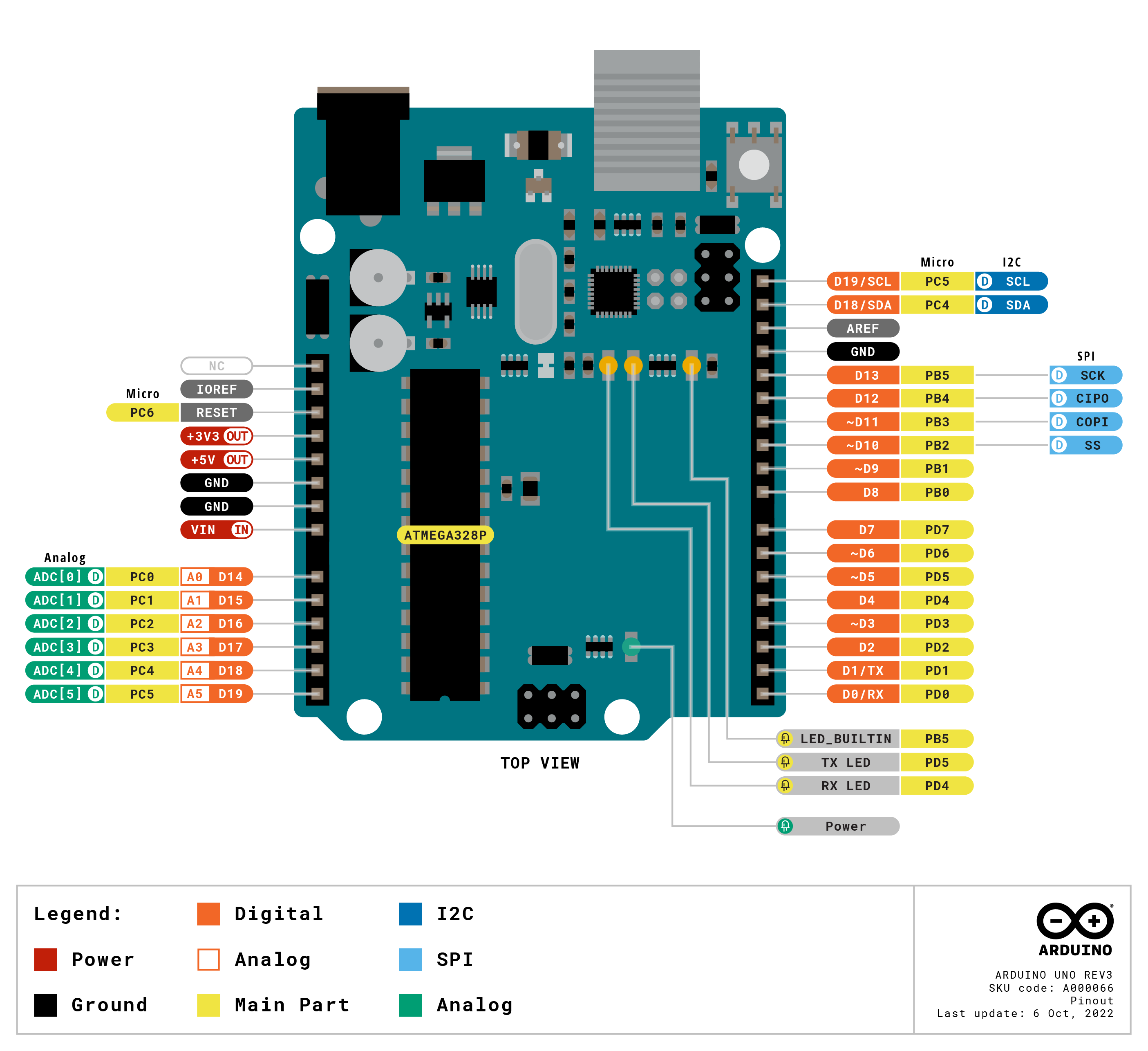
This is the GPIO signal line mapping from the Arduino Uno R3 [3]
header bindet with arduino-header-r3 to the set of
Grove connectors provided as Laced Grove Signal Interface.
phandle index to shield –> |
Signal : Meaning |
|
|---|---|---|
|
D0: UART-RX (SERCOM5) |
<&grove_uart_header 0 …>↳
|
|
D1: UART-TX (SERCOM5) |
<&grove_uart_header 1 …>↳
|
|
D2 |
not wired |
|
D3 |
not wired |
|
D4 |
not wired |
|
D5 |
not wired |
|
D6 |
not wired |
|
D7 |
not wired |
|
D8 |
not wired |
|
D9 |
not wired |
|
D10: SPI-CS |
not wired |
|
D11: SPI-MOSI |
not wired |
|
D12: SPI-MISO |
not wired |
|
D13: SPI-CLK |
not wired |
|
D14: A0 as GPIO |
not wired |
|
D15: A1 as GPIO |
not wired |
|
D16: A2 as GPIO |
not wired |
|
D17: A3 as GPIO |
not wired |
|
D18: I2C-SDA |
<&grove_i2c_header 1 …>,↳
<&arduino_header 20 …> |
|
D19: I2C-SCL |
<&grove_i2c_header 0 …>↳
<&arduino_header 21 …> |
|
D20: ADC6 as GPIO |
not wired |
|
||
|
||
|
||
|
||
|
||
|
||
|
||
|
||
|
||
|
||
|
The corresponding mapping is always board or SOC specific. In addition
to the PWM signal line mapping, the valid references to the PWM
function units in the SOC or on the board are therefore also defined
as Grove PWM Labels. The following table reflects the currently
supported mapping for seeeduino_cm0, but this list will be
growing up with further development and maintenance.
This list must not be complete!
Grove PWM Label |
phandle index to shield –> |
Signal : Meaning |
|
|---|---|---|---|
|
D0: UART-RX |
not possible |
|
|
D1: UART-TX |
not possible |
|
|
D2 |
not wired |
|
|
D3 |
not wired |
|
|
D4 |
not wired |
|
|
D5 |
not wired |
|
|
D6 |
not wired |
|
|
D7 |
not wired |
|
|
D8 |
not wired |
|
|
D9 |
not wired |
|
|
D10: SPI-CS |
not wired |
|
|
D11: SPI-MOSI |
not wired |
|
|
D12: SPI-MISO |
not wired |
|
|
D13: SPI-CLK |
not wired |
|
|
D14: A0 |
not wired |
|
|
D15: A1 |
not wired |
|
|
D16: A2 |
not wired |
|
|
D17: A3 |
not wired |
|
|
|
D18: I2C-SDA |
|
|
|
D19: I2C-SCL |
|
|
D20: ADC6 |
not wired |
|
|
|||
|
|||
|
|||
|
|||
|
|||
|
|||
|
|||
|
|||
|
|||
|
|||
|
System Clock
The SAMD21 MCU is configured to use the 32 kHz external crystal with the on-chip PLL generating the 48 MHz system clock. The internal APB and GCLK unit are set up in the same way as the upstream Arduino libraries.
GPIO (PWM) Ports
The SAMD21 MCU has 2 GPIO ports, 3 PWM able Timer/Capture-Counter (TCC) and
2 simple Timer/Counter (TC). On the Cortex-M0+, TCC2 channel 1 is available
on first user LED (blue), all other user LEDs can be controlled as GPIO.
Only if CONFIG_PWM_SAM0_TCC is enabled then the first user
LED (blue) is driven by TCC2 instead of by GPIO. All channels of TCC0 are
available on the Arduino UNO R3 header and the Grove connectors (see
above, Laced Grove Signal Interface).
ADC/DAC Ports
The SAMD21 MCU has 1 DAC and 1 ADC. On the Cortex-M0+, the DAC voltage
output (VOUT) is available on A0 of the Arduino UNO R3 header. The ADC
channels 2-5 and 10 are available on A1-A5 of the Arduino UNO R3 header.
The external voltage reference VREFA can be used optional for the DAC and
ADC on same time and is available on AREF of the Arduino UNO R3 header.
SPI Port
The SAMD21 MCU has 6 SERCOM based SPIs. On the Cortex-M0+, SERCOM1 can be put
into SPI mode and used to connect to devices over D11 (MOSI), D12 (MISO), and
D13 (SCK) of the Arduino UNO R3 header.
I2C Port
The SAMD21 MCU has 6 SERCOM based I2Cs. On the Cortex-M0+, SERCOM3 is available
on D18 (SDA) and D19 (SCL) of the Arduino UNO R3 header and on pin 1 (SCL)
and pin 2 (SDA) of the two Grove I2C connectors.
Serial Port
The SAMD21 MCU has 6 SERCOM based USARTs. On the Cortex-M0+, SERCOM2 is
available on D0 (RX) and D1 (TX) of the Arduino UNO R3 header and is the
Zephyr console. SERCOM5 is available on pin 1 (RX) and pin 2 (TX) of the Grove
UART connector and is an optional second serial port for applications.
USB Device Port
The SAMD21 MCU has a (native) USB device port that can be used to communicate with a host PC. See the USB device support samples sample applications for more, such as the USB CDC-ACM sample which sets up a virtual serial port that echos characters back to the host PC. As an alternative to the default Zephyr console on serial port the Bridle USB Console Snippet (usb-console) can be used to enable CDC ACM and switch the console to USB:
USB device idVendor=2886, idProduct=8027, bcdDevice= 3.06
USB device strings: Mfr=1, Product=2, SerialNumber=3
Product: Seeeduino Cortex-M0+ (CDC ACM)
Manufacturer: Seeed LLC
SerialNumber: 8159F378B63F73EE
Programming and Debugging
The Cortex-M0+ ships the BOSSA compatible UF2 bootloader [2] also known as Arduino Zero Bootloader [4], a modern SAM-BA [1] (Boot Assistant) replacement. The bootloader can be entered by pressing the RST button twice:
USB device idVendor=2886, idProduct=0027, bcdDevice= 2.00
USB device strings: Mfr=1, Product=2, SerialNumber=0
Product: Seeeduino_Cortex_M0+
Manufacturer: Arduino LLC
Additionally, if CONFIG_USB_CDC_ACM is enabled then the
bootloader will be entered automatically when you run west flash.
Tip
When ever you need to restore this original bootloader you should read and following the directions in Flashing the Arduino Bootloader using DAP Link [8]. There is also a backup copy of the original bootloader together with a ready to use Segger JFlash control file inside the Bridel project:
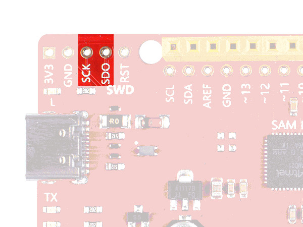
There is also a SWD header (J10, not populated) on board which have to be used with tools like Segger J-Link for programming for bootloader restore or direct programming and debugging.
Flashing
Build the Zephyr kernel and the Hello World sample application:
west build -b seeeduino_cm0 -p -d build/seeeduino_cm0 zephyr/samples/hello_world
Connect the Cortex-M0+ to your host computer using USB.
Connect a 3.3 V USB to serial adapter to the board and to the host. See the Serial Port section above for the board’s pin connections.
Run your favorite terminal program to listen for output. Under Linux the terminal should be
/dev/ttyUSB0. For example:minicom -D /dev/ttyUSB0 -oThe -o option tells minicom not to send the modem initialization string. Connection should be configured as follows:
Speed: 115200
Data: 8 bits
Parity: None
Stop bits: 1
Pressing the RST button twice quickly to enter bootloader mode.
Flash the image:
west flash -d build/seeeduino_cm0
You should see “Hello World! seeeduino_cm0” in your terminal.
Debugging
Debugging is only possible over SWD!
Do the for the debug session necessary steps as before except enter the bootloader mode and the flashing.
Connect the Segger J-Link to the SWD header (J10).
Flash the image and attach a debugger to your board:
west build -b seeeduino_cm0 -p -d build/seeeduino_cm0 zephyr/samples/hello_world -- -DBOARD_FLASH_RUNNER=openocd
west debug -d build/seeeduino_cm0
You should ends up in a debug console (e.g. a GDB session).
More Samples
LED Blinky
west build -b seeeduino_cm0 -p -d build/seeeduino_cm0 zephyr/samples/basic/blinky
west flash -d build/seeeduino_cm0
LED Fade
west build -b seeeduino_cm0 -p -d build/seeeduino_cm0 zephyr/samples/basic/fade_led
west flash -d build/seeeduino_cm0
Basic Threads
west build -b seeeduino_cm0 -p -d build/seeeduino_cm0 zephyr/samples/basic/threads
west flash -d build/seeeduino_cm0
Hello Shell with USB-CDC/ACM Console
west build -b seeeduino_cm0 -p -S usb-console -d build/seeeduino_cm0 bridle/samples/helloshell
west flash -d build/seeeduino_cm0
Simple test execution on target
(text in bold is a command input)
uart:~$ hello -h
hello - say hello
uart:~$ hello
Hello from shell.

uart:~$ hwinfo devid
Length: 16
ID: 0x17d5dcb1101244738159f378b63f73ee

uart:~$ kernel version
Zephyr version 3.6.0

uart:~$ bridle version
Bridle version 3.6.1

uart:~$ bridle version long
Bridle version 3.6.1.0

uart:~$ bridle info
Zephyr: 3.6.0
Bridle: 3.6.1

uart:~$ device list
devices:
- eic@40001800 (READY)
- gpio@41004480 (READY)
- gpio@41004400 (READY)
- snippet_cdc_acm_console_uart (READY)
- sercom@42001c00 (READY)
- sercom@42001000 (READY)
- tc@42003800 (DISABLED)
- tc@42003000 (DISABLED)
- adc@42004000 (READY)
- dac@42004800 (READY)
- nvmctrl@41004000 (READY)
- sercom@42001400 (READY)
- tcc@42002800 (READY)
- tcc@42002000 (READY)

uart:~$ history
[  0] history
[  1] device list
[  2] bridle info
[  3] bridle version long
[  4] bridle version
[  5] kernel version
[  6] hwinfo devid
[  7] hello
[  8] hello -h
Operate with the red Rx user LED:
uart:~$ gpio get gpio@41004480 3
0

uart:~$ gpio conf gpio@41004480 3 ol0

uart:~$ gpio set gpio@41004480 3 1
uart:~$ gpio set gpio@41004480 3 0

uart:~$ gpio blink gpio@41004480 3
Hit any key to exit
Operate with the blue user LED:
uart:~$ pwm usec tcc@42002800 1 20000 20000
uart:~$ pwm usec tcc@42002800 1 20000 19000
uart:~$ pwm usec tcc@42002800 1 20000 18000
uart:~$ pwm usec tcc@42002800 1 20000 17000
uart:~$ pwm usec tcc@42002800 1 20000 16000
uart:~$ pwm usec tcc@42002800 1 20000 15000
uart:~$ pwm usec tcc@42002800 1 20000 10000
uart:~$ pwm usec tcc@42002800 1 20000 5000
uart:~$ pwm usec tcc@42002800 1 20000 2500
uart:~$ pwm usec tcc@42002800 1 20000 500
uart:~$ pwm usec tcc@42002800 1 20000 0
Operate with the loop-back wire from A0 (DAC CH0 VOUT) to A1 (ADC CH2 AIN):
uart:~$ dac setup dac@42004800 0 10
uart:~$ adc adc@42004000 resolution 12
uart:~$ adc adc@42004000 acq_time 10 us
uart:~$ adc adc@42004000 channel positive 2

uart:~$ dac write_value dac@42004800 0 512
uart:~$ adc adc@42004000 read 2
read: 2035

uart:~$ dac write_value dac@42004800 0 1023
uart:~$ adc adc@42004000 read 2
read: 4068
uart:~$ flash read nvmctrl@41004000 18894 40
00018894: 73 65 65 65 64 75 69 6e  6f 5f 63 6d 30 00 48 65 |seeeduin o_cm0.He|
000188A4: 6c 6c 6f 20 57 6f 72 6c  64 21 20 49 27 6d 20 54 |llo Worl d! I'm T|
000188B4: 48 45 20 53 48 45 4c 4c  20 66 72 6f 6d 20 25 73 |HE SHELL  from %s|
000188C4: 0a 00 69 6c 6c 65 67 61  6c 20 6f 70 74 69 6f 6e |..illega l option|

uart:~$ flash read nvmctrl@41004000 3c000 40
0003C000: ff ff ff ff ff ff ff ff  ff ff ff ff ff ff ff ff |........ ........|
0003C010: ff ff ff ff ff ff ff ff  ff ff ff ff ff ff ff ff |........ ........|
0003C020: ff ff ff ff ff ff ff ff  ff ff ff ff ff ff ff ff |........ ........|
0003C030: ff ff ff ff ff ff ff ff  ff ff ff ff ff ff ff ff |........ ........|

uart:~$ flash test nvmctrl@41004000 3c000 400 2
Erase OK.
Write OK.
Verified OK.
Erase OK.
Write OK.
Verified OK.
Erase-Write-Verify test done.

uart:~$ flash read nvmctrl@41004000 3c000 40
0003C000: 00 01 02 03 04 05 06 07  08 09 0a 0b 0c 0d 0e 0f |........ ........|
0003C010: 10 11 12 13 14 15 16 17  18 19 1a 1b 1c 1d 1e 1f |........ ........|
0003C020: 20 21 22 23 24 25 26 27  28 29 2a 2b 2c 2d 2e 2f | !"#$%&' ()*+,-./|
0003C030: 30 31 32 33 34 35 36 37  38 39 3a 3b 3c 3d 3e 3f |01234567 89:;<=>?|

uart:~$ flash page_info 3c000
Page for address 0x3c000:
start offset: 0x3c000
size: 256
index: 960

uart:~$ flash erase nvmctrl@41004000 3c000 400
Erase success.

uart:~$ flash read nvmctrl@41004000 3c000 40
0003C000: ff ff ff ff ff ff ff ff  ff ff ff ff ff ff ff ff |........ ........|
0003C010: ff ff ff ff ff ff ff ff  ff ff ff ff ff ff ff ff |........ ........|
0003C020: ff ff ff ff ff ff ff ff  ff ff ff ff ff ff ff ff |........ ........|
0003C030: ff ff ff ff ff ff ff ff  ff ff ff ff ff ff ff ff |........ ........|
The Cortex-M0+ has no on-board I2C devices. For this example the Grove Temperature and Barometer Sensor – BMP280 [11] was connected.
uart:~$ log enable none i2c_sam0

uart:~$ i2c scan sercom@42001400
     0  1  2  3  4  5  6  7  8  9  a  b  c  d  e  f
00:             -- -- -- -- -- -- -- -- -- -- -- --
10: -- -- -- -- -- -- -- -- -- -- -- -- -- -- -- --
20: -- -- -- -- -- -- -- -- -- -- -- -- -- -- -- --
30: -- -- -- -- -- -- -- -- -- -- -- -- -- -- -- --
40: -- -- -- -- -- -- -- -- -- -- -- -- -- -- -- --
50: -- -- -- -- -- -- -- -- -- -- -- -- -- -- -- --
60: -- -- -- -- -- -- -- -- -- -- -- -- -- -- -- --
70: -- -- -- -- -- -- -- 77
1 devices found on sercom@42001400

uart:~$ log enable inf i2c_sam0
The I2C address 0x77 is a Bosch BMP280 Air Pressure Sensor and their
Chip-ID can read from register 0xd0. The Chip-ID must be 0x58:
uart:~$ i2c read_byte sercom@42001400 77 d0
Output: 0x58