NXP LPCXPRESSO51U68
Overview
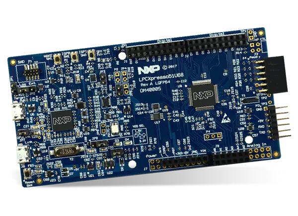
The LPCXpresso51u68 development board uses an NXP LPC51U68 MCU based on an ARM CORTEX-M0+ core.
Hardware
LPC51U68 M0+ running at up to 150 MHz
Memory
256KB of flash memory
96KB of SRAM
On-board high-speed USB based debug probe with CMSIS-DAP and J-Link protocol support, can debug the on-board LPC51U68 or an external target
External debug probe option
Tri-color LED, target reset, ISP & interrupt/user buttons for easy testing of software functionality
Expansion options based on Arduino UNO and PMOD™, plus additional expansion port pins
FTDI UART Connector
More information can be found here:
Supported Features
The lpcxpresso51u68 support the following features:
Interface |
Controller |
Driver/Component |
|---|---|---|
NVIC |
on-chip |
nested vector interrupt controller |
SYSTICK |
on-chip |
systick |
IOCON |
on-chip |
pinmux |
CLOCK |
on-chip |
clock and reset control |
GPIO |
on-chip |
gpio |
I2C |
on-chip |
i2c master/slave controller |
UART |
on-chip |
serial port-polling; serial port interrupt |
SPI |
on-chip |
SPI master |
Other hardware is not yet supported on Zephyr.
Connections and IOs
The IOCON controller can be used to configure the LPC51U68 pins.
Name |
Function |
Usage |
|---|---|---|
PIO0_0 |
UART |
USART RX |
PIO0_1 |
UART |
USART TX |
PIO1_10 |
GPIO |
GREEN LED |
PIO0_29 |
GPIO |
RED LED |
PIO1_9 |
GPIO |
BLUE_LED |
PIO0_25 |
I2C |
I2C SCL |
PIO0_26 |
I2C |
I2C SDA |
PIO0_18 |
SPI |
SPI MISO |
PIO0_19 |
SPI |
SPI SCK |
PIO0_20 |
SPI |
SPI MOSI |
PIO1_1 |
SPI |
SPI SSEL2 |
Programming and Debugging
Build and flash applications as usual (see Building an Application and Run an Application for more details).
Configuring a Debug Probe
A debug probe is used for both flashing and debugging the board. This board is configured by default to use the LPC-Link2 CMSIS-DAP Onboard Debug Probe, however the pyOCD Debug Host Tools do not support this probe so you must reconfigure the board for one of the following debug probes instead.
LPC-Link2 J-Link Onboard Debug Probe
Install the J-Link Debug Host Tools and make sure they are in your search path.
Follow the instructions in LPC-Link2 J-Link Onboard Debug Probe to program the J-Link firmware.
Configuring a Console
Connect a USB to FTDI RX, TX & GND pins to P3 Connector.
Use the following settings with your serial terminal of choice (minicom, putty, etc.):
Speed: 115200
Data: 8 bits
Parity: None
Stop bits: 1
Flashing
Here is an example for the Hello World application.
# From the root of the zephyr repository
west build -b lpcxpresso51u68 samples/hello_world
west flash
***** Booting Zephyr OS build zephyr-v2.6.0-934-g4c438c0c7d13 *****
Hello World! lpcxpresso51u68
Debugging
Here is an example for the Hello World application.
# From the root of the zephyr repository
west build -b lpcxpresso51u68 samples/hello_world
west debug
Open a serial terminal, step through the application in your debugger, and you should see the following message in the terminal:
***** Booting Zephyr OS build zephyr-v2.6.0-934-g4c438c0c7d13 *****
Hello World! lpcxpresso51u68