NXP LPCXpresso55S16
Overview
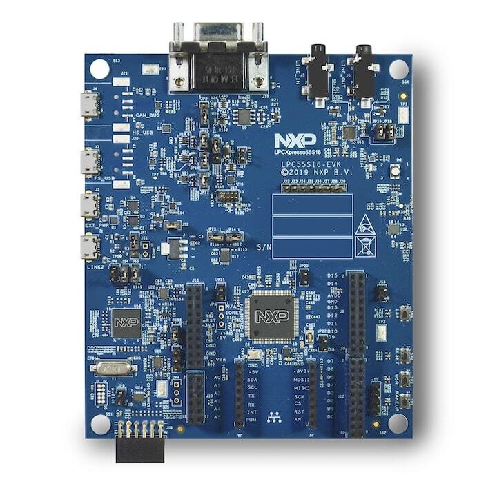
The LPCXpresso55S16 board provides the ideal platform for evaluation of the LPC55S1x/LPC551x MCU family, based on the Arm® Cortex®-M33 architecture. Arduino® UNO compatible shield connectors are included, with additional expansion ports around the Arduino footprint, along with a PMod/host interface port and MikroElektronika Click module site.
Hardware
LPC55S16 Arm® Cortex®-M33 microcontroller running at up to 150 MHz
256 KB flash and 96 KB SRAM on-chip
LPC-Link2 debug high speed USB probe with VCOM port
I2C and SPI USB bridging to the LPC device via LPC-Link2 probe
MikroElektronika Click expansion option
LPCXpresso expansion connectors compatible with Arduino UNO
PMod compatible expansion / host connector
Reset, ISP, wake, and user buttons for easy testing of software functionality
Tri-color LED
Full-speed USB device / host port
High-speed USB device / host port
UART header for external serial to USB cable
CAN Transceiver
Stereo audio codec with in/out line
NXP FXOS8700CQ accelerometer
For more information about the LPC55S16 SoC and LPCXPresso55S16 board, see:
Supported Features
The lpcxpresso55s16 board configuration supports the hardware features listed below. For additional features not yet supported, please also refer to the NXP LPCXPRESSO55S69 , which is the superset board in NXP’s LPC55xx series. NXP prioritizes enabling the superset board with NXP’s Full Platform Support for Zephyr. Therefore, the lpcxpresso55s69 board may have additional features already supported, which can also be re-used on this lpcxpresso55s16 board:
Interface |
Controller |
Driver/Component |
|---|---|---|
NVIC |
on-chip |
nested vector interrupt controller |
SYSTICK |
on-chip |
systick |
IOCON |
on-chip |
pinmux |
GPIO |
on-chip |
gpio |
I2C |
on-chip |
i2c |
SPI |
on-chip |
spi |
USART |
on-chip |
serial port-polling; serial port-interrupt |
SENSOR |
off-chip |
fxos8700 trigger |
CLOCK |
on-chip |
clock_control |
CAN |
on-chip |
canbus |
RNG |
on-chip |
entropy; random |
IAP |
on-chip |
flash programming |
Other hardware features are not currently enabled.
Currently available targets for this board are:
lpcxpresso55s16
Connections and IOs
The LPC55S16 SoC has IOCON registers, which can be used to configure the functionality of a pin.
Name |
Function |
Usage |
|---|---|---|
PIO0_5 |
GPIO |
ISP SW4 |
PIO0_26 |
SPI |
SPI MOSI |
PIO0_29 |
USART |
USART RX |
PIO0_30 |
USART |
USART TX |
PIO1_1 |
SPI |
SPI SSEL1 |
PIO1_2 |
SPI |
SPI SCK |
PIO1_3 |
SPI |
SPI MISO |
PIO1_4 |
GPIO |
RED LED |
PIO1_6 |
GPIO |
BLUE_LED |
PIO1_7 |
GPIO |
GREEN LED |
PIO1_9 |
GPIO |
USR SW3 |
PIO1_18 |
GPIO |
Wakeup SW1 |
PIO1_20 |
I2C |
I2C SCL |
PIO1_21 |
I2C |
I2C SDA |
PIO1_26 |
GPIO |
FXOS8700 INT1 |
PIO1_22 |
CAN |
CAN RXD |
PIO1_27 |
CAN |
CAN TXD |
System Clock
The LPC55S16 SoC is configured to use PLL1 clocked from the external 24MHz crystal, running at 144MHz as a source for the system clock. When the flash controller is enabled, the core clock will be reduced to 96MHz. The application may reconfigure clocks after initialization, provided that the core clock is always set to 96MHz when flash programming operations are performed.
Serial Port
The LPC55S16 SoC has 8 FLEXCOMM interfaces for serial communication. One is configured as USART for the console, one is configured for I2C, and the remaining are not used.
Programming and Debugging
Build and flash applications as usual (see Building an Application and Run an Application for more details).
Configuring a Debug Probe
A debug probe is used for both flashing and debugging the board. This board is configured by default to use the LPC-Link2 CMSIS-DAP Onboard Debug Probe, however the pyOCD Debug Host Tools does not yet support the LPC55S16 so you must reconfigure the board for one of the J-Link debug probe instead.
First install the J-Link Debug Host Tools and make sure they are in your search path.
Then follow the instructions in LPC-Link2 J-Link Onboard Debug Probe to program the J-Link firmware. Please make sure you have the latest firmware for this board.
Configuring a Console
Connect a USB cable from your PC to J1 (LINK2), and use the serial terminal of your choice (minicom, putty, etc.) with the following settings:
Speed: 115200
Data: 8 bits
Parity: None
Stop bits: 1
Flashing
Here is an example for the Hello World application.
# From the root of the zephyr repository
west build -b lpcxpresso55s16 samples/hello_world
west flash
Open a serial terminal, reset the board (press the RESET button), and you should see the following message in the terminal:
***** Booting Zephyr OS v2.2.0 *****
Hello World! lpcxpresso55s16
Debugging
Here is an example for the Hello World application.
# From the root of the zephyr repository
west build -b lpcxpresso55s16 samples/hello_world
west debug
Open a serial terminal, step through the application in your debugger, and you should see the following message in the terminal:
***** Booting Zephyr OS zephyr-v2.2.0 *****
Hello World! lpcxpresso55s16