The PicoBoy (Color)
The PicoBoy is a powerful mini handheld measuring just 3×5 ㎝. It is suitable for learning programming, developing your own games or simply playing with it. All you need is a PC, the PicoBoy and a USB-C cable. As the PicoBoy based on the RP2040 SoC [62] by Raspberry Pi Ltd. and is compatible with the Raspberry Pi Pico programming model and process, there are countless other tutorials, examples and libraries on the internet to make programming easier.
The PicoBoy Color (PBC) is the further development of the popular PicoBoy handheld, now with a color display for even more gaming fun. Whether you want to learn programming, develop your own games or simply play, the PicoBoy Color offers a wide range of possibilities. Although the original PicoBoy remains a great starting point for beginners and school classes, the PicoBoy Color offers an enhanced gaming experience and new possibilities for those who want more.
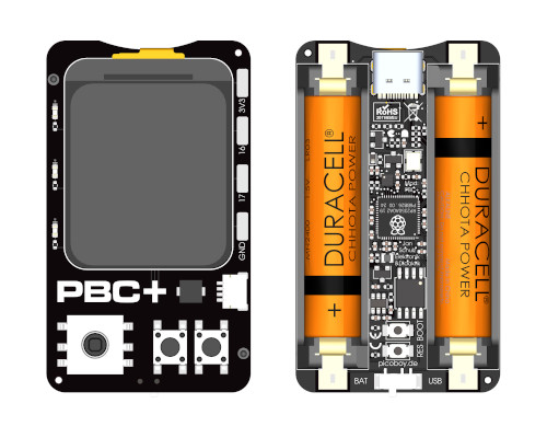
The PicoBoy Color Plus (PBC+), based on the new RP2350 SoC [65] by Raspberry Pi Ltd., is a new extended and in some points optimized version of the PicoBoy Color. The computing and memory performance has been significantly increased and missing functions have been added.
Board Overview
Hardware
The PicoBoy [16] is a special mini sized RP2040 development board.
Features and Resources |
Printed Circuit Board |
5V/125~250㎃ 3.0~3.3V/180~200㎃ 133㎒ 2㎆ 264㎅ USB-C CR2032 UF2 RST BOOT UP|DOWN|LEFT|RIGHT|ENTER RED YELLOW GREEN OLED PASSIVE 3-DOF 9 4 4 1 1
Design Data
|

|
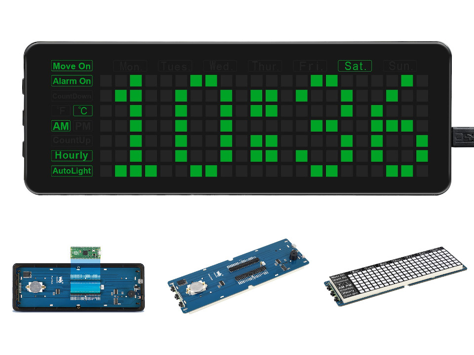
The PicoBoy Color [18] is a special mini sized RP2040 development board.
Features and Resources |
Printed Circuit Board |
5V/125~250㎃ 3.0~3.3V/100~150㎃ 133㎒ 2㎆ 264㎅ USB-C 2×AAA UF2 RST BOOT USER UP|DOWN|LEFT|RIGHT|ENTER RED YELLOW GREEN LCD PASSIVE 11 5 1 1 1
Design Data
|
|
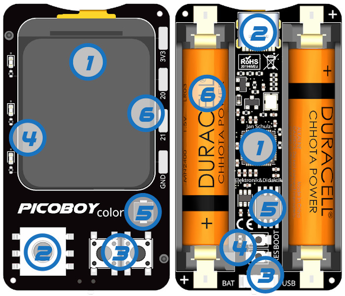
The PicoBoy Color Plus [21] is a special mini sized RP2350A development board.
Features and Resources |
Printed Circuit Board |
5V/125~250㎃ 3.0~3.3V/100~150㎃ 150㎒ 16㎆ 520㎅ USB-C 2×AAA UF2 RST BOOT USER UP|DOWN|LEFT|RIGHT|ENTER RED YELLOW GREEN RGB LCD PASSIVE 3-DOF 11 5 1 1 1 1
Design Data
|
|
Positions

|
|---|
Front side:
Back side:
|
Data Sheets
Flash partitions
QSPI NOR-Flash |
bootrom |
code_partition |
storage_partition |
|---|---|---|---|
primary 2㎆ |
256B |
1㎆ - 256B |
1㎆ |
|
|---|
Front side:
Back side:
|
Data Sheets
Flash partitions
QSPI NOR-Flash |
bootrom |
code_partition |
storage_partition |
|---|---|---|---|
primary 2㎆ |
256B |
1㎆ - 256B |
1㎆ |
|
|---|
Front side:
Back side:
|
Data Sheets
Flash partitions
QSPI NOR-Flash |
code_partition |
storage_partition |
|---|---|---|
primary 16㎆ |
1㎆ |
15㎆ |
secondary N/A |
– |
– |
Pinouts
The peripherals of the RP2040 SoC [62] and RP2350 SoC [65] can be routed to various pins on the board. The configuration of these routes can be modified through DTS. Please refer to the datasheet to see the possible routings for each peripheral. The default assignments for the PicoBoy (Color/Plus) on-board wiring is defined below. There is only an edge connector on the PicoBoy Color Plus, otherwise not. The PicoBoy Color and Color Plus has solder pads with additional signals routed to outside of the board.
Pin Mapping |
Default Zephyr On-Board Mapping
Buttons
LEDs
Display and Speaker
Sensor I/O
GPIO and ADC
|
Pin Mapping |
Default Zephyr On-Board Mapping
Buttons
LEDs
Display and Speaker
Sensors via solder pads
GPIO and ADC
|
Pin Mapping |
Default Zephyr On-Board Mapping
Buttons
LEDs
Display and Speaker
Sensor I/O and via Qwiic / STEMMA QT
Serial I/O via solder pads
GPIO and ADC
|
Supported Features
Similar to the Raspberry Pi Pico the PicoBoy (Color/Plus) board configuration supports the following hardware features:
Peripheral |
Kconfig option |
Devicetree compatible |
Zephyr API |
|---|---|---|---|
PINCTRL |
|||
GPIO |
|||
UART |
|||
UDC (USB Device Controller) |
|||
I2C |
|||
SPI |
|||
PWM |
|||
ADC |
|||
Temperature (Sensor) |
|||
RTC |
|||
Timer (Counter) |
|||
Watchdog Timer (WDT) |
|||
Flash |
|||
PIO |
N/A |
||
UART (PIO) |
|||
SPI (PIO) |
|||
DMA |
|||
HWINFO |
N/A |
||
VREG |
|||
RESET |
|||
CLOCK |
|||
NVIC |
N/A |
Nested Vector Interrupts Controller |
|
SYSTICK |
N/A |
arm,v8m-systick |
(!) POWMAN with VREG and QMI (Flash) on RP2350 not yet supported by Zephyr.
See section Peripherals RP2350 in upstream issue: https://github.com/zephyrproject-rtos/zephyr/issues/53810
Other hardware features are not currently supported by Zephyr. The default configuration can be found in the following Kconfig file:
Board Configurations
The PicoBoy boards can be configured only for the following single use cases.
west build -b picoboy/rp2040
Use the native USB device port with CDC-ACM as Zephyr console and for the shell.
west build -b picoboy_color/rp2040
Use the native USB device port with CDC-ACM as Zephyr console and for the shell.
west build -b picoboy_color_plus/rp2350a/m33
Use the native USB device port with CDC-ACM as Zephyr console and for the shell.
Connections and IOs
The PicoBoy [17] and PicoBoy Color [19] and PicoBoy Color Plus [22] website has detailed information about board connections. Download the different datasheets there or as linked above on the positions for more details.
System Clock
The RP2040 [62] MCU is configured to use the 12㎒ external crystal with the on-chip PLL generating the 125㎒ system clock. The RP2350 [65] MCU is configured to use the 12㎒ external crystal with the on-chip PLL generating the 150㎒ system clock. The internal AHB and APB units are set up in the same way as the upstream Raspberry Pi Pico C/C++ SDK [10] libraries.
GPIO (PWM) Ports
The RP2040 [62] MCU has 1 GPIO cell which covers all I/O pads and 8 PWM function unit each with 2 channels beside a dedicated Timer unit. The RP2350 [65] MCU has 1 GPIO cell which covers all I/O pads and 12 PWM function unit each with 2 channels beside a dedicated Timer unit. On the PicoBoy, only 4 PWM channels are available on the three user LEDs and the passive magnetic speaker. On the PicoBoy Color and PicoBoy Color Plus, only 5 PWM channels are available on the LCD backlight, the three user LEDs and the passive magnetic speaker.
ADC/TS Ports
The RP2040 [62] and RP2350 [65] MCU has 1 ADC with 4 channels and an additional fifth channel for the on-chip temperature sensor (TS). The ADC channels 0-3 are no available for any on-board function on the PicoBoy and PicoBoy Color and may be completely unusable, but they ar all configured. On the PicoBoy Color Plus ADC channel 3 will be used for internal on-board voltage monitoring.
SPI Port
The RP2040 [62] and RP2350 [65] MCU has 2 SPIs. The serial bus SPI0 is connect to the on-board OLED display or LCD over GP19 (MOSI), GP16 (MISO), GP18 (SCK), and GP17 (CSn), but only MOSI and SCK is used for write-only communication. The display chip-select signal will driven as simple GPIO by GP10 and the display itself does not provide any data out signal (MISO). SPI1 is not available in any default setup.
On the PicoBoy Color Plus the serial bus SPI1 will be used internaly to drive the on-board RGB LED over a one-wire digital signal on GP11 (MOSI).
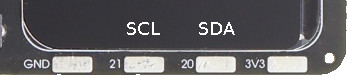
I2C Port
The RP2040 [62] and RP2350 [65] MCU has 2 I2Cs. On the PicoBoy and PicoBoy Color Plus, serial bus I2C0 is connect to the on-board acceleration sensor over GP20 (I2C0_SDA), GP21 (I2C0_SCL). I2C1 is not available in any default setup.
The PicoBoy Color has no on-board acceleration sensor, but the serial bus I2C0 is connect to the on-board solder pads. The I2C port cannot be used at the same time as the UART port. Both share the required lines on GP20 and GP21.
The I2C port on solder pads is enabled by default.

The PicoBoy Color Plus also provides the I2C0 serial bus with the same pin assignment for external sensors via a Maker Port as a Qwiic / STEMMA QT connector. On the solder pads, however, the I2C0 is optionally accessible with GP16 (SDA) and GP17 (SCL).
The I2C port on solder pads is disabled by default.
Serial Port
The RP2040 [62] and RP2350 [65] MCU has 2 UARTs. On the PicoBoy, neither UART0 nor UART1 are available in any of the default setups. When ever a Zephyr serial console will be needed, the USB port have to be used.
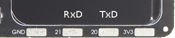
On the PicoBoy Color, the serial port UART1 is connect to the on-board solder pads over GP20 (UART1_TX), GP21 (UART1_RX). UART0 is not available in any default setup. The UART port cannot be used at the same time as the I2C port. Both share the required lines on GP20 and GP21.
The UART port on solder pads is disabled by default.

On the PicoBoy Color Plus, the serial port UART0 is connect to the on-board solder pads over GP16 (UART0_TX), GP17 (UART0_RX). UART1 would be optional available on the Maker Port (Qwiic / STEMMA QT connector). The UART port cannot be used at the same time as the I2C port on the solder pads. Both share the required lines on GP16 and GP17.
The UART port on solder pads is enabled by default.
USB Device Port
The RP2040 [62] and RP2350 [65] MCU has a (native) USB device port that can be used to communicate with a host PC. See the USB sample applications for more, such as the USB CDC ACM UART sample sample which sets up a virtual serial port that echos characters back to the host PC. The PicoBoy, PicoBoy Color and PicoBoy Color Plus provide the Zephyr console per default on the USB port as CDC ACM:
USB device idVendor=2e8a, idProduct=000a, bcdDevice= 4.03
USB device strings: Mfr=1, Product=2, SerialNumber=3
Product: PicoBoy (CDC ACM)
Manufacturer: JSED (Raspberry Pi)
SerialNumber: BD774B2618DAAA7D
USB device idVendor=2e8a, idProduct=000a, bcdDevice= 4.03
USB device strings: Mfr=1, Product=2, SerialNumber=3
Product: PicoBoy Color (CDC ACM)
Manufacturer: JSED (Raspberry Pi)
SerialNumber: B69CA314D5626E5B
USB device idVendor=2e8a, idProduct=000a, bcdDevice= 4.03
USB device strings: Mfr=1, Product=2, SerialNumber=3
Product: PicoBoy Color Plus (CDC ACM)
Manufacturer: JSED (Raspberry Pi)
SerialNumber: B163A72F0CF0C97A
Programmable I/O (PIO)
The RP2040 SoC [62] comes with two and RP2350 [65] with three PIO periherals. These are simple co-processors that are designed for I/O operations. The PIOs run a custom instruction set, generated from a custom assembly language. PIO programs are assembled using pioasm, a tool provided by Raspberry Pi. Further information can be found in the Raspberry Pi Pico C/C++ SDK [10] document, section with title “Using PIOASM, the PIO Assembler”.
Zephyr does not (currently) assemble PIO programs. Rather, they should be manually assembled and embedded in source code. An example of how this is done can be found at drivers/serial/uart_rpi_pico_pio.c or drivers/spi/spi_rpi_pico_pio.c.
Programming and Debugging
Flashing
The PicoBoy can only be flashed with a UF2 file. There is no SWD connector.
Using UF2
By default, building an app for the PicoBoy or PicoBoy Color board will
generate a build/zephyr/zephyr.uf2 file. If the board is powered on
with the BOOTSEL button pressed, it will appear on the host as a mass
storage device:
USB device idVendor=2e8a, idProduct=0003, bcdDevice= 1.00
USB device strings: Mfr=1, Product=2, SerialNumber=0
Product: RP2 Boot
Manufacturer: Raspberry Pi
SerialNumber: E0C9125B0D9B
USB device idVendor=2e8a, idProduct=0003, bcdDevice= 1.00
USB device strings: Mfr=1, Product=2, SerialNumber=0
Product: RP2 Boot
Manufacturer: Raspberry Pi
SerialNumber: E0C9125B0D9B
USB device idVendor=2e8a, idProduct=000f, bcdDevice= 1.00
USB device strings: Mfr=1, Product=2, SerialNumber=0
Product: RP2350 Boot
Manufacturer: Raspberry Pi
SerialNumber: E9DB4B801D503140
The UF2 file should be drag-and-dropped or copied on command line to the device, which will then flash the PicoBoy, PicoBoy Color or PicoBoy Color Plus board.
RP2040 Boot-ROM
Each RP2040 SoC [62] ships the UF2 compatible [6] bootloader pico-bootrom-rp2040 [12], a native support in silicon. The full source for the RP2040 bootrom at pico-bootrom-rp2040 [12] includes versions B0, B1 and B2 of the bootrom, which correspond to the same silicon revisions, respectively.
Note that every time you build a program for the RP2040, the Pico SDK selects
an appropriate second stage bootloader based on what kind of external QSPI
Flash type the board configuration you are building for was giving. There
are several versions of boot2 [11] for different flash chips, and each one is
exactly 256 bytes of code which is put right at the start of the eventual
program binary. On Zephyr the boot2 versions are part of the
Raspberry Pi Pico HAL [15] module. Possible selections:
CONFIG_RP2_FLASH_AT25SF128A:CONFIG_RP2_FLASH_GENERIC_03H:CONFIG_RP2_FLASH_IS25LP080:CONFIG_RP2_FLASH_W25Q080:CONFIG_RP2_FLASH_W25X10CL:
The PicoBoy and PicoBoy Color board set this option to
CONFIG_RP2_FLASH_W25Q080. Further information can be found in the
RP2040 Datasheet [63], sections with title “Bootrom” and
“Processor Controlled Boot Sequence” or
Brian Starkey’s Blog article Pico serial bootloader [14]
RP2350 Boot-ROM
Each RP2350 SoC [65] ships the UF2 compatible [6] bootloader pico-bootrom-rp2350 [13], a native support in silicon. The full source for the RP2350 bootrom at pico-bootrom-rp2350 [13] includes versions A2, A3 and A4 of the bootrom, which correspond to the same silicon revisions, respectively.
Debugging
The PicoBoy, PicoBoy Color or PicoBoy Color Plus does not provide any SWD connector, thus debugging software is not possible.
Basic Samples
LED Blinky and Fade
Red User LED Blinky by GPIO
See also Zephyr sample: Blinky.
west build -b picoboy/rp2040 -p -d build/picoboy zephyr/samples/basic/blinky
west flash -d build/picoboy
Red User LED Blinky by PWM
See also Zephyr sample: PWM Blinky.
west build -b picoboy/rp2040 -p -d build/picoboy zephyr/samples/basic/blinky_pwm
west flash -d build/picoboy
All User LED Fade by PWM
See also Zephyr sample: Fade LED.
west build -b picoboy/rp2040 -p -d build/picoboy zephyr/samples/basic/fade_led
west flash -d build/picoboy
Red User LED On/Off by GPIO Button (Joystick ENTER)
See also Zephyr sample: Button.
west build -b picoboy/rp2040 -p -d build/picoboy zephyr/samples/basic/button
west flash -d build/picoboy
Red User LED Blinky by GPIO
See also Zephyr sample: Blinky.
west build -b picoboy_color/rp2040 -p -d build/picoboy zephyr/samples/basic/blinky
west flash -d build/picoboy
Red User LED Blinky by PWM
See also Zephyr sample: PWM Blinky.
west build -b picoboy_color/rp2040 -p -d build/picoboy zephyr/samples/basic/blinky_pwm
west flash -d build/picoboy
All User LED Fade by PWM
See also Zephyr sample: Fade LED.
west build -b picoboy_color/rp2040 -p -d build/picoboy zephyr/samples/basic/fade_led
west flash -d build/picoboy
Red User LED On/Off by GPIO Button (left side user button BACK)
See also Zephyr sample: Button.
west build -b picoboy_color/rp2040 -p -d build/picoboy zephyr/samples/basic/button
west flash -d build/picoboy
Red User LED Blinky by GPIO
See also Zephyr sample: Blinky.
west build -b picoboy_color_plus/rp2350a/m33 -p -d build/picoboy zephyr/samples/basic/blinky
west flash -d build/picoboy
Red User LED Blinky by PWM
See also Zephyr sample: PWM Blinky.
west build -b picoboy_color_plus/rp2350a/m33 -p -d build/picoboy zephyr/samples/basic/blinky_pwm
west flash -d build/picoboy
All User LED Fade by PWM
See also Zephyr sample: Fade LED.
west build -b picoboy_color_plus/rp2350a/m33 -p -d build/picoboy zephyr/samples/basic/fade_led
west flash -d build/picoboy
Red User LED On/Off by GPIO Button (left side user button BACK)
See also Zephyr sample: Button.
west build -b picoboy_color_plus/rp2350a/m33 -p -d build/picoboy zephyr/samples/basic/button
west flash -d build/picoboy
SK6805 (WS2812) LED Test Pattern by SPI
See also Zephyr sample: LED strip.
west build -b picoboy_color_plus/rp2350a/m33 -p -d build/picoboy zephyr/samples/drivers/led/led_strip -- -DCONFIG_SAMPLE_LED_UPDATE_DELAY=500
west flash -d build/picoboy
Hello Shell on USB-CDC/ACM Console
Hello Shell
west build -b picoboy/rp2040 -p -d build/picoboy bridle/samples/helloshell
west flash -d build/picoboy
Simple test execution on target
(text in bold is a command input)
uart:~$ hello -h
hello - say hello
uart:~$ hello
Hello from shell.
uart:~$ hwinfo devid
Length: 8
ID: 0xbd774b2618daaa7d

uart:~$ kernel version
Zephyr version 4.3.99

uart:~$ bridle version
Bridle version 4.3.99

uart:~$ bridle version long
Bridle version 4.3.99.0

uart:~$ bridle info
Zephyr: 4.3.99
Bridle: 4.3.99
uart:~$ device list
devices:
- clock-controller@40008000 (READY)
  DT node labels: clocks
- reset-controller@4000c000 (READY)
  DT node labels: reset
- cdc_acm_console_uart (READY)
  DT node labels: cdc_acm_console_uart
- watchdog@40058000 (READY)
  DT node labels: wdt0
- timer@40054000 (READY)
  DT node labels: timer
- dma@50000000 (READY)
  DT node labels: dma
- gpio-port@0 (READY)
  DT node labels: gpio0
- usbd@50110000 (READY)
  DT node labels: usbd zephyr_udc0
- adc@4004c000 (READY)
  DT node labels: adc
- flash-controller@18000000 (READY)
  DT node labels: ssi
- i2c@40044000 (READY)
  DT node labels: i2c0
- pwm@40050000 (READY)
  DT node labels: pwm
- vreg@40064000 (READY)
  DT node labels: vreg
- rtc@4005c000 (READY)
  DT node labels: rtc
- pwm_leds (READY)
  DT node labels: pwm_leds
- dietemp (READY)
  DT node labels: die_temp
- stk8ba58@18 (READY)
  DT node labels: stk8ba58
uart:~$ history
[  0] history
[  1] device list
[  2] bridle info
[  3] bridle version long
[  4] bridle version
[  5] kernel version
[  6] hwinfo devid
[  7] hello
[  8] hello -h
Operate with the on-chip voltage regulator unit:
uart:~$ regulator vlist vreg
0.800 V
0.850 V
0.900 V
0.950 V
1.000 V
1.050 V
1.100 V
1.150 V
1.200 V
1.250 V
1.300 V
Trigger a power-of/on sequence:
uart:~$ hwinfo reset_cause
reset caused by:
- pin

uart:~$ regulator disable vreg
*** Booting Zephyr OS build v4.3.99…***
Hello World! I'm THE SHELL from picoboy
uart:~$ hwinfo reset_cause
reset caused by:
- power-on reset
Note
PWM LED conflicts with GPIO!
Operations with the red user LED in PWM mode will fail when ever the corresponding GPIO line 5 was configured as digital output. This condition is irreversible at runtime within the shell and requires a system reset.
Operate with the red user LED PWM_LED at GP5 / PWM5 (PWM2CHA):
uart:~$ led on pwm_leds 0
pwm_leds: turning on LED 0
uart:~$ led set_brightness pwm_leds 0 10
pwm_leds: setting LED 0 brightness to 10
uart:~$ led set_brightness pwm_leds 0 50
pwm_leds: setting LED 0 brightness to 50
uart:~$ led set_brightness pwm_leds 0 100
pwm_leds: setting LED 0 brightness to 100
uart:~$ led off pwm_leds 0
pwm_leds: turning off LED 0
Note
PWM conflicts with GPIO!
Operations with the red user LED in PWM mode will fail when ever the corresponding GPIO line 5 was configured as digital output. This condition is irreversible at runtime within the shell and requires a system reset.
Operate with the red user LED PWM_LED at GP5 / PWM5 (PWM2CHA):
uart:~$ pwm usec pwm 5 20000 20000
uart:~$ pwm usec pwm 5 20000 19000
uart:~$ pwm usec pwm 5 20000 18000
uart:~$ pwm usec pwm 5 20000 17000
uart:~$ pwm usec pwm 5 20000 16000
uart:~$ pwm usec pwm 5 20000 15000
uart:~$ pwm usec pwm 5 20000 10000
uart:~$ pwm usec pwm 5 20000 5000
uart:~$ pwm usec pwm 5 20000 2500
uart:~$ pwm usec pwm 5 20000 500
uart:~$ pwm usec pwm 5 20000 0
Operate with the PASSIVE magnetic speaker at GP15 / PWM15 (PWM7CHB):
concert pitch: 440 ㎐
Piezo middle frequency: 1,000 ㎑
Piezo resonance: 4,000 ㎑
Piezo high frequency: 10,000 ㎑
uart:~$ pwm usec pwm 15 2273 1136
uart:~$ pwm usec pwm 15 2000 1000
uart:~$ pwm usec pwm 15 250 125
uart:~$ pwm usec pwm 15 100 50
Operate with the red user LED LED at GP5:
uart:~$ gpio get gpio0 5
0

uart:~$ gpio conf gpio0 5 oh0

uart:~$ gpio set gpio0 5 1
uart:~$ gpio set gpio0 5 0

uart:~$ gpio blink gpio0 5
Hit any key to exit
Operate with the user joystick center button ENTER at GP0:
uart:~$ gpio get gpio0 0
0

uart:~$ gpio conf gpio0 0 iul
uart:~$ gpio get gpio0 0
0
uart:~$ gpio get gpio0 0
1
uart:~$ gpio get gpio0 0
0
Operate with the channels:
ADC0, pulled to unknown voltage level
ADC1, pulled to unknown voltage level
ADC2, pulled to unknown voltage level
ADC3, pulled to unknown voltage level
on-chip temperature sensor on channel ADC4
uart:~$ adc adc@4004c000 resolution 12
uart:~$ adc adc@4004c000 print
adc@4004c000:
Gain: 1
Reference: INTERNAL
Acquisition Time: 0
Channel ID: 0
Differential: 0
Resolution: 12
uart:~$ adc adc@4004c000 read 0
read: 681
uart:~$ adc adc@4004c000 read 1
read: 617
uart:~$ adc adc@4004c000 read 2
read: 745
uart:~$ adc adc@4004c000 read 3
read: 692
uart:~$ adc adc@4004c000 read 4
read: 749
Operate with the on-chip RTC unit:
uart:~$ rtc get rtc
RTC not set
uart:~$ rtc set rtc 2024-11-23T18:37:55

uart:~$ rtc get rtc
2024-11-23T18:37:59.000
Operate with the on-chip timer unit:
uart:~$ timer oneshot timer 0 1000000
timer: Alarm triggered
Erase, Write and Verify
uart:~$ flash read ssi e0000 40
000E0000: ff ff ff ff ff ff ff ff  ff ff ff ff ff ff ff ff |........ ........|
000E0010: ff ff ff ff ff ff ff ff  ff ff ff ff ff ff ff ff |........ ........|
000E0020: ff ff ff ff ff ff ff ff  ff ff ff ff ff ff ff ff |........ ........|
000E0030: ff ff ff ff ff ff ff ff  ff ff ff ff ff ff ff ff |........ ........|

uart:~$ flash test ssi e0000 1000 2
Erase OK.
Write OK.
Verified OK.
Erase OK.
Write OK.
Verified OK.
Erase-Write-Verify test done.
uart:~$ flash read ssi e0000 40
000E0000: 00 01 02 03 04 05 06 07  08 09 0a 0b 0c 0d 0e 0f |........ ........|
000E0010: 10 11 12 13 14 15 16 17  18 19 1a 1b 1c 1d 1e 1f |........ ........|
000E0020: 20 21 22 23 24 25 26 27  28 29 2a 2b 2c 2d 2e 2f | !"#$%&' ()*+,-./|
000E0030: 30 31 32 33 34 35 36 37  38 39 3a 3b 3c 3d 3e 3f |01234567 89:;<=>?|

uart:~$ flash page_info e0000
Page for address 0xe0000:
start offset: 0xe0000
size: 4096
index: 224
uart:~$ flash erase ssi e0000 1000
Erase success.

uart:~$ flash read ssi e0000 40
000E0000: ff ff ff ff ff ff ff ff  ff ff ff ff ff ff ff ff |........ ........|
000E0010: ff ff ff ff ff ff ff ff  ff ff ff ff ff ff ff ff |........ ........|
000E0020: ff ff ff ff ff ff ff ff  ff ff ff ff ff ff ff ff |........ ........|
000E0030: ff ff ff ff ff ff ff ff  ff ff ff ff ff ff ff ff |........ ........|
The PicoBoy has the on-board acceleration sensor connected on I2C0.
uart:~$ i2c scan i2c0
     0  1  2  3  4  5  6  7  8  9  a  b  c  d  e  f
00:             -- -- -- -- -- -- -- -- -- -- -- --
10: -- -- -- -- -- -- -- -- 18 -- -- -- -- -- -- --
20: -- -- -- -- -- -- -- -- -- -- -- -- -- -- -- --
30: -- -- -- -- -- -- -- -- -- -- -- -- -- -- -- --
40: -- -- -- -- -- -- -- -- -- -- -- -- -- -- -- --
50: -- -- -- -- -- -- -- -- -- -- -- -- -- -- -- --
60: -- -- -- -- -- -- -- -- -- -- -- -- -- -- -- --
70: -- -- -- -- -- -- -- --
1 devices found on i2c0
The I2C address 0x18 is a Sensortek STK8BA58 [44] 3D Acceleration Sensor
and their Chip-ID can read from register 0x0. The Chip-ID must be
0x87:
uart:~$ i2c read_byte i2c0 18 0
Output: 0x87
uart:~$ sensor info
device name: dietemp, vendor: Raspberry Pi Foundation, model: pico-temp, friendly name: RP2040 chip temperature
device name: stk8ba58@18, vendor: Sensortek Technology Corporation, model: stk8ba58, friendly name: on-board accelerometer
on-chip temperature sensor
uart:~$ sensor get dietemp
channel type=12(die_temp) index=0 shift=5 num_samples=1 value=96691043776ns (29.905286)
on-board 3-axis accelerometer
Default attributes for all three axis:
range,
full_scale: 2g = 19.613300 ㎨ODR,
sampling_frequency: 250 ㎐sleep,
configuration: 25 ㎳ (low-power mode)
uart:~$ sensor attr_get stk8ba58@18 accel_xyz full_scale
stk8ba58@18(channel=accel_xyz, attr=full_scale) value=19.613300
uart:~$ sensor attr_get stk8ba58@18 accel_xyz sampling_frequency
stk8ba58@18(channel=accel_xyz, attr=sampling_frequency) value=250.000000
uart:~$ sensor attr_get stk8ba58@18 accel_xyz configuration
stk8ba58@18(channel=accel_xyz, attr=configuration) value=25.000000
uart:~$ sensor get stk8ba58@18
channel type=0(accel_x) index=0 shift=4 num_samples=1 value=35274098880ns (5.756698)
channel type=1(accel_y) index=0 shift=4 num_samples=1 value=35274098880ns (-1.729892)
channel type=2(accel_z) index=0 shift=4 num_samples=1 value=35274098880ns (-8.774402)
channel type=3(accel_xyz) index=0 shift=4 num_samples=1 value=35274098880ns, (5.756698, -1.729892, -8.774402)
Hello Shell
west build -b picoboy_color/rp2040 -p -d build/picoboy bridle/samples/helloshell
west flash -d build/picoboy
Simple test execution on target
(text in bold is a command input)
uart:~$ hello -h
hello - say hello
uart:~$ hello
Hello from shell.
uart:~$ hwinfo devid
Length: 8
ID: 0xb69ca314d5626e5b

uart:~$ kernel version
Zephyr version 4.3.99

uart:~$ bridle version
Bridle version 4.3.99

uart:~$ bridle version long
Bridle version 4.3.99.0

uart:~$ bridle info
Zephyr: 4.3.99
Bridle: 4.3.99
uart:~$ device list
devices:
- clock-controller@40008000 (READY)
  DT node labels: clocks
- reset-controller@4000c000 (READY)
  DT node labels: reset
- cdc_acm_console_uart (READY)
  DT node labels: cdc_acm_console_uart
- watchdog@40058000 (READY)
  DT node labels: wdt0
- timer@40054000 (READY)
  DT node labels: timer
- dma@50000000 (READY)
  DT node labels: dma
- gpio-port@0 (READY)
  DT node labels: gpio0
- usbd@50110000 (READY)
  DT node labels: usbd zephyr_udc0
- adc@4004c000 (READY)
  DT node labels: adc
- flash-controller@18000000 (READY)
  DT node labels: ssi
- i2c@40044000 (READY)
  DT node labels: i2c0
- pwm@40050000 (READY)
  DT node labels: pwm
- vreg@40064000 (READY)
  DT node labels: vreg
- rtc@4005c000 (READY)
  DT node labels: rtc
- lcd_backlight_en (READY)
  DT node labels: lcd_backlight_en
- pwm_leds (READY)
  DT node labels: pwm_leds
- dietemp (READY)
  DT node labels: die_temp
uart:~$ history
[  0] history
[  1] device list
[  2] bridle info
[  3] bridle version long
[  4] bridle version
[  5] kernel version
[  6] hwinfo devid
[  7] hello
[  8] hello -h
Operate with the on-chip voltage regulator unit:
uart:~$ regulator vlist vreg
0.800 V
0.850 V
0.900 V
0.950 V
1.000 V
1.050 V
1.100 V
1.150 V
1.200 V
1.250 V
1.300 V
Trigger a power-of/on sequence:
uart:~$ hwinfo reset_cause
reset caused by:
- pin

uart:~$ regulator disable vreg
*** Booting Zephyr OS build v4.3.99…***
Hello World! I'm THE SHELL from picoboy
uart:~$ hwinfo reset_cause
reset caused by:
- power-on reset
Operate with the fixed voltage regulator for LCD backlight:
uart:~$ regulator is_enabled lcd_backlight_en
Regulator is enabled

uart:~$ regulator disable lcd_backlight_en

uart:~$ regulator is_enabled lcd_backlight_en
Regulator is disabled
Note
PWM LED conflicts with GPIO!
Operations with the red user LED in PWM mode will fail when ever the corresponding GPIO line 14 was configured as digital output. This condition is irreversible at runtime within the shell and requires a system reset.
Operate with the red user LED PWM_LED at GP14 / PWM14 (PWM7CHA):
uart:~$ led on pwm_leds 0
pwm_leds: turning on LED 0
uart:~$ led set_brightness pwm_leds 0 10
pwm_leds: setting LED 0 brightness to 10
uart:~$ led set_brightness pwm_leds 0 50
pwm_leds: setting LED 0 brightness to 50
uart:~$ led set_brightness pwm_leds 0 100
pwm_leds: setting LED 0 brightness to 100
uart:~$ led off pwm_leds 0
pwm_leds: turning off LED 0
Note
PWM conflicts with GPIO!
Operations with the red user LED in PWM mode will fail when ever the corresponding GPIO line 14 was configured as digital output. This condition is irreversible at runtime within the shell and requires a system reset.
Operate with the red user LED PWM_LED at GP14 / PWM14 (PWM7CHA):
uart:~$ pwm usec pwm 14 20000 20000
uart:~$ pwm usec pwm 14 20000 19000
uart:~$ pwm usec pwm 14 20000 18000
uart:~$ pwm usec pwm 14 20000 17000
uart:~$ pwm usec pwm 14 20000 16000
uart:~$ pwm usec pwm 14 20000 15000
uart:~$ pwm usec pwm 14 20000 10000
uart:~$ pwm usec pwm 14 20000 5000
uart:~$ pwm usec pwm 14 20000 2500
uart:~$ pwm usec pwm 14 20000 500
uart:~$ pwm usec pwm 14 20000 0
Operate with the PASSIVE magnetic speaker at GP15 / PWM15 (PWM7CHB):
concert pitch: 440 ㎐
Piezo middle frequency: 1,000 ㎑
Piezo resonance: 4,000 ㎑
Piezo high frequency: 10,000 ㎑
uart:~$ pwm usec pwm 15 2273 1136
uart:~$ pwm usec pwm 15 2000 1000
uart:~$ pwm usec pwm 15 250 125
uart:~$ pwm usec pwm 15 100 50
Operate with the red user LED LED at GP14:
uart:~$ gpio get gpio0 14
0

uart:~$ gpio conf gpio0 14 oh0

uart:~$ gpio set gpio0 14 1
uart:~$ gpio set gpio0 14 0

uart:~$ gpio blink gpio0 14
Hit any key to exit
Operate with the user joystick center button ENTER at GP0:
uart:~$ gpio get gpio0 0
0

uart:~$ gpio conf gpio0 0 iul
uart:~$ gpio get gpio0 0
0
uart:~$ gpio get gpio0 0
1
uart:~$ gpio get gpio0 0
0
Operate with the channels:
ADC3, pulled to unknown voltage level
on-chip temperature sensor on channel ADC4
uart:~$ adc adc@4004c000 resolution 12
uart:~$ adc adc@4004c000 print
adc@4004c000:
Gain: 1
Reference: INTERNAL
Acquisition Time: 0
Channel ID: 0
Differential: 0
Resolution: 12
uart:~$ adc adc@4004c000 read 3
read: 692
uart:~$ adc adc@4004c000 read 4
read: 749
Operate with the on-chip RTC unit:
uart:~$ rtc get rtc
RTC not set
uart:~$ rtc set rtc 2024-11-23T18:37:55

uart:~$ rtc get rtc
2024-11-23T18:37:59.000
Operate with the on-chip timer unit:
uart:~$ timer oneshot timer 0 1000000
timer: Alarm triggered
Erase, Write and Verify
uart:~$ flash read ssi e0000 40
000E0000: ff ff ff ff ff ff ff ff  ff ff ff ff ff ff ff ff |........ ........|
000E0010: ff ff ff ff ff ff ff ff  ff ff ff ff ff ff ff ff |........ ........|
000E0020: ff ff ff ff ff ff ff ff  ff ff ff ff ff ff ff ff |........ ........|
000E0030: ff ff ff ff ff ff ff ff  ff ff ff ff ff ff ff ff |........ ........|

uart:~$ flash test ssi e0000 1000 2
Erase OK.
Write OK.
Verified OK.
Erase OK.
Write OK.
Verified OK.
Erase-Write-Verify test done.
uart:~$ flash read ssi e0000 40
000E0000: 00 01 02 03 04 05 06 07  08 09 0a 0b 0c 0d 0e 0f |........ ........|
000E0010: 10 11 12 13 14 15 16 17  18 19 1a 1b 1c 1d 1e 1f |........ ........|
000E0020: 20 21 22 23 24 25 26 27  28 29 2a 2b 2c 2d 2e 2f | !"#$%&' ()*+,-./|
000E0030: 30 31 32 33 34 35 36 37  38 39 3a 3b 3c 3d 3e 3f |01234567 89:;<=>?|

uart:~$ flash page_info e0000
Page for address 0xe0000:
start offset: 0xe0000
size: 4096
index: 224
uart:~$ flash erase ssi e0000 1000
Erase success.

uart:~$ flash read ssi e0000 40
000E0000: ff ff ff ff ff ff ff ff  ff ff ff ff ff ff ff ff |........ ........|
000E0010: ff ff ff ff ff ff ff ff  ff ff ff ff ff ff ff ff |........ ........|
000E0020: ff ff ff ff ff ff ff ff  ff ff ff ff ff ff ff ff |........ ........|
000E0030: ff ff ff ff ff ff ff ff  ff ff ff ff ff ff ff ff |........ ........|
The PicoBoy Color has no on-board I2C devices. For this example the Grove Temperature and Barometer Sensor – BMP280 [24] was connected.
uart:~$ i2c scan i2c0
     0  1  2  3  4  5  6  7  8  9  a  b  c  d  e  f
00:             -- -- -- -- -- -- -- -- -- -- -- --
10: -- -- -- -- -- -- -- -- -- -- -- -- -- -- -- --
20: -- -- -- -- -- -- -- -- -- -- -- -- -- -- -- --
30: -- -- -- -- -- -- -- -- -- -- -- -- -- -- -- --
40: -- -- -- -- -- -- -- -- -- -- -- -- -- -- -- --
50: -- -- -- -- -- -- -- -- -- -- -- -- -- -- -- --
60: -- -- -- -- -- -- -- -- -- -- -- -- -- -- -- --
70: -- -- -- -- -- -- -- 77
1 devices found on i2c0
The I2C address 0x77 is a Bosch BMP280 Air Pressure Sensor and their
Chip-ID can read from register 0xd0. The Chip-ID must be 0x58:
uart:~$ i2c read_byte i2c0 77 d0
Output: 0x58
uart:~$ sensor info
device name: dietemp, vendor: Raspberry Pi Foundation, model: pico-temp, friendly name: RP2040 chip temperature
on-chip temperature sensor
uart:~$ sensor get dietemp
channel type=12(die_temp) index=0 shift=6 num_samples=1 value=144882710603ns (39.202207)
Hello Shell
west build -b picoboy_color_plus/rp2350a/m33 -p -d build/picoboy bridle/samples/helloshell
west flash -d build/picoboy
Simple test execution on target
(text in bold is a command input)
uart:~$ hello -h
hello - say hello
uart:~$ hello
Hello from shell.
uart:~$ hwinfo devid
Length: 8
ID: 0xb163a72f0cf0c97a

uart:~$ kernel version
Zephyr version 4.3.99

uart:~$ bridle version
Bridle version 4.3.99

uart:~$ bridle version long
Bridle version 4.3.99.0

uart:~$ bridle info
Zephyr: 4.3.99
Bridle: 4.3.99
uart:~$ device list
devices:
- clock-controller@40010000 (READY)
  DT node labels: clocks
- reset-controller@40020000 (READY)
  DT node labels: reset
- cdc_acm_console_uart (READY)
  DT node labels: cdc_acm_console_uart
- uart@40070000 (READY)
  DT node labels: uart0 rpipico_serial pico_serial
- watchdog@400d8000 (READY)
  DT node labels: wdt0
- timer@400b8000 (READY)
  DT node labels: timer1
- timer@400b0000 (READY)
  DT node labels: timer0
- dma@50000000 (READY)
  DT node labels: dma
- gpio-port@0 (READY)
  DT node labels: gpio0
- usbd@50110000 (READY)
  DT node labels: usbd zephyr_udc0
- adc@400a0000 (READY)
  DT node labels: adc
- flash-controller@400d0000 (READY)
  DT node labels: qmi
- i2c@40090000 (READY)
  DT node labels: i2c0 grove_i2c rpipico_i2c0 rpipico_i2c pico_i2c0 pico_i2c
- pwm@400a8000 (READY)
  DT node labels: pwm grove_pwm_d20 grove_pwm_d21
- lcd_backlight_en (READY)
  DT node labels: lcd_backlight_en
- pwm_leds (READY)
  DT node labels: pwm_leds
- dietemp (READY)
  DT node labels: die_temp
- stk8ba58@18 (READY)
  DT node labels: stk8ba58
uart:~$ history
[  0] history
[  1] device list
[  2] bridle info
[  3] bridle version long
[  4] bridle version
[  5] kernel version
[  6] hwinfo devid
[  7] hello
[  8] hello -h
POWMAN with VREG not yet supported
See section Peripherals RP2350 in upstream issue: https://github.com/zephyrproject-rtos/zephyr/issues/53810
Operate with the fixed voltage regulator for LCD backlight:
uart:~$ regulator is_enabled lcd_backlight_en
Regulator is enabled

uart:~$ regulator disable lcd_backlight_en

uart:~$ regulator is_enabled lcd_backlight_en
Regulator is disabled
Note
PWM LED conflicts with GPIO!
Operations with the red user LED in PWM mode will fail when ever the corresponding GPIO line 14 was configured as digital output. This condition is irreversible at runtime within the shell and requires a system reset.
Operate with the red user LED PWM_LED at GP14 / PWM14 (PWM7CHA):
uart:~$ led on pwm_leds 0
pwm_leds: turning on LED 0
uart:~$ led set_brightness pwm_leds 0 10
pwm_leds: setting LED 0 brightness to 10
uart:~$ led set_brightness pwm_leds 0 50
pwm_leds: setting LED 0 brightness to 50
uart:~$ led set_brightness pwm_leds 0 100
pwm_leds: setting LED 0 brightness to 100
uart:~$ led off pwm_leds 0
pwm_leds: turning off LED 0
Note
PWM conflicts with GPIO!
Operations with the red user LED in PWM mode will fail when ever the corresponding GPIO line 14 was configured as digital output. This condition is irreversible at runtime within the shell and requires a system reset.
Operate with the red user LED PWM_LED at GP14 / PWM14 (PWM7CHA):
uart:~$ pwm usec pwm 14 20000 20000
uart:~$ pwm usec pwm 14 20000 19000
uart:~$ pwm usec pwm 14 20000 18000
uart:~$ pwm usec pwm 14 20000 17000
uart:~$ pwm usec pwm 14 20000 16000
uart:~$ pwm usec pwm 14 20000 15000
uart:~$ pwm usec pwm 14 20000 10000
uart:~$ pwm usec pwm 14 20000 5000
uart:~$ pwm usec pwm 14 20000 2500
uart:~$ pwm usec pwm 14 20000 500
uart:~$ pwm usec pwm 14 20000 0
Operate with the PASSIVE magnetic speaker at GP15 / PWM15 (PWM7CHB):
concert pitch: 440 ㎐
Piezo middle frequency: 1,000 ㎑
Piezo resonance: 4,000 ㎑
Piezo high frequency: 10,000 ㎑
uart:~$ pwm usec pwm 15 2273 1136
uart:~$ pwm usec pwm 15 2000 1000
uart:~$ pwm usec pwm 15 250 125
uart:~$ pwm usec pwm 15 100 50
Operate with the red user LED LED at GP14:
uart:~$ gpio get gpio0 14
0

uart:~$ gpio conf gpio0 14 oh0

uart:~$ gpio set gpio0 14 1
uart:~$ gpio set gpio0 14 0

uart:~$ gpio blink gpio0 14
Hit any key to exit
Operate with the user joystick center button ENTER at GP0:
uart:~$ gpio get gpio0 0
0

uart:~$ gpio conf gpio0 0 iul
uart:~$ gpio get gpio0 0
0
uart:~$ gpio get gpio0 0
1
uart:~$ gpio get gpio0 0
0
Operate with the channels:
on-board voltage monitor on channel ADC3
on-chip temperature sensor on channel ADC4
uart:~$ adc adc@400a0000 resolution 12
uart:~$ adc adc@400a0000 print
adc@400a0000:
Gain: 1
Reference: INTERNAL
Acquisition Time: 0
Channel ID: 0
Differential: 0
Resolution: 12
uart:~$ adc adc@400a0000 read 3
read: 1940
uart:~$ adc adc@400a0000 read 4
read: 749
Operate with the two on-chip timer units:
uart:~$ timer oneshot timer0 0 1000000
timer0: Alarm triggered
uart:~$ timer oneshot timer1 0 1000000
timer1: Alarm triggered
Erase, Write and Verify
uart:~$ flash read qmi e0000 40
000E0000: ff ff ff ff ff ff ff ff  ff ff ff ff ff ff ff ff |........ ........|
000E0010: ff ff ff ff ff ff ff ff  ff ff ff ff ff ff ff ff |........ ........|
000E0020: ff ff ff ff ff ff ff ff  ff ff ff ff ff ff ff ff |........ ........|
000E0030: ff ff ff ff ff ff ff ff  ff ff ff ff ff ff ff ff |........ ........|

uart:~$ flash test qmi e0000 1000 2
Erase OK.
Write OK.
Verified OK.
Erase OK.
Write OK.
Verified OK.
Erase-Write-Verify test done.
uart:~$ flash read qmi e0000 40
000E0000: 00 01 02 03 04 05 06 07  08 09 0a 0b 0c 0d 0e 0f |........ ........|
000E0010: 10 11 12 13 14 15 16 17  18 19 1a 1b 1c 1d 1e 1f |........ ........|
000E0020: 20 21 22 23 24 25 26 27  28 29 2a 2b 2c 2d 2e 2f | !"#$%&' ()*+,-./|
000E0030: 30 31 32 33 34 35 36 37  38 39 3a 3b 3c 3d 3e 3f |01234567 89:;<=>?|

uart:~$ flash page_info e0000
Page for address 0xe0000:
start offset: 0xe0000
size: 4096
index: 224
uart:~$ flash erase qmi e0000 1000
Erase success.

uart:~$ flash read qmi e0000 40
000E0000: ff ff ff ff ff ff ff ff  ff ff ff ff ff ff ff ff |........ ........|
000E0010: ff ff ff ff ff ff ff ff  ff ff ff ff ff ff ff ff |........ ........|
000E0020: ff ff ff ff ff ff ff ff  ff ff ff ff ff ff ff ff |........ ........|
000E0030: ff ff ff ff ff ff ff ff  ff ff ff ff ff ff ff ff |........ ........|
The PicoBoy Color Plus has the on-board acceleration sensor connected on I2C0. For this example the Grove Temperature and Barometer Sensor – BMP280 [24] was also connected to I2C0 via the Qwiic / STEMMA QT connector (Maker Port).
uart:~$ i2c scan i2c0
     0  1  2  3  4  5  6  7  8  9  a  b  c  d  e  f
00:             -- -- -- -- -- -- -- -- -- -- -- --
10: -- -- -- -- -- -- -- -- 18 -- -- -- -- -- -- --
20: -- -- -- -- -- -- -- -- -- -- -- -- -- -- -- --
30: -- -- -- -- -- -- -- -- -- -- -- -- -- -- -- --
40: -- -- -- -- -- -- -- -- -- -- -- -- -- -- -- --
50: -- -- -- -- -- -- -- -- -- -- -- -- -- -- -- --
60: -- -- -- -- -- -- -- -- -- -- -- -- -- -- -- --
70: -- -- -- -- -- -- -- 77
2 devices found on i2c0
The I2C address 0x18 is a Sensortek STK8BA58 [44] 3D Acceleration Sensor
and their Chip-ID can read from register 0x0. The Chip-ID must be
0x87:
uart:~$ i2c read_byte i2c0 18 0
Output: 0x87
The I2C address 0x77 is a Bosch BMP280 [43] Air Pressure Sensor and their
Chip-ID can read from register 0xd0. The Chip-ID must be 0x58:
uart:~$ i2c read_byte i2c0 77 d0
Output: 0x58
uart:~$ sensor info
device name: stk8ba58@18, vendor: Sensortek Technology Corporation, model: stk8ba58, friendly name: on-board accelerometer
device name: dietemp, vendor: Raspberry Pi Foundation, model: pico-temp, friendly name: RP2350 chip temperature
on-chip temperature sensor
uart:~$ sensor get dietemp
channel type=12(die_temp) index=0 shift=5 num_samples=1 value=14554473307ns (31.067401)
on-board 3-axis accelerometer
Default attributes for all three axis:
range,
full_scale: 2g = 19.613300 ㎨ODR,
sampling_frequency: 250 ㎐sleep,
configuration: 25 ㎳ (low-power mode)
uart:~$ sensor attr_get stk8ba58@18 accel_xyz full_scale
stk8ba58@18(channel=accel_xyz, attr=full_scale) value=19.613300
uart:~$ sensor attr_get stk8ba58@18 accel_xyz sampling_frequency
stk8ba58@18(channel=accel_xyz, attr=sampling_frequency) value=250.000000
uart:~$ sensor attr_get stk8ba58@18 accel_xyz configuration
stk8ba58@18(channel=accel_xyz, attr=configuration) value=25.000000
uart:~$ sensor get stk8ba58@18
channel type=0(accel_x) index=0 shift=4 num_samples=1 value=61368586658ns (-1.345472)
channel type=1(accel_y) index=0 shift=4 num_samples=1 value=61368586658ns (3.651995)
channel type=2(accel_z) index=0 shift=4 num_samples=1 value=61368586658ns (-9.812338)
channel type=3(accel_xyz) index=0 shift=4 num_samples=1 value=61368586658ns, (-1.345472, 3.651995, -9.812338)
uart:~$ sensor trig stk8ba58@18 on data_ready
Enabled trigger idx=1 data_ready on device stk8ba58@18
[00:03:39.519,000] <inf> sensor_shell: sensor=stk8ba58, chan=accel_x, num_samples=138, data=-1.085779
[00:03:39.519,000] <inf> sensor_shell: sensor=stk8ba58, chan=accel_y, num_samples=138, data=4.899622
[00:03:39.519,000] <inf> sensor_shell: sensor=stk8ba58, chan=accel_z, num_samples=138, data=-9.081102
[00:03:44.566,000] <inf> sensor_shell: sensor=stk8ba58, chan=accel_x, num_samples=138, data=-1.096364
[00:03:44.566,000] <inf> sensor_shell: sensor=stk8ba58, chan=accel_y, num_samples=138, data=4.910068
[00:03:44.566,000] <inf> sensor_shell: sensor=stk8ba58, chan=accel_z, num_samples=138, data=-9.079361
[00:03:49.613,000] <inf> sensor_shell: sensor=stk8ba58, chan=accel_x, num_samples=138, data=-1.088982
[00:03:49.613,000] <inf> sensor_shell: sensor=stk8ba58, chan=accel_y, num_samples=138, data=4.913968
[00:03:49.613,000] <inf> sensor_shell: sensor=stk8ba58, chan=accel_z, num_samples=138, data=-9.078735
[00:03:54.661,000] <inf> sensor_shell: sensor=stk8ba58, chan=accel_x, num_samples=138, data=-1.087241
[00:03:54.661,000] <inf> sensor_shell: sensor=stk8ba58, chan=accel_y, num_samples=138, data=4.902616
[00:03:54.661,000] <inf> sensor_shell: sensor=stk8ba58, chan=accel_z, num_samples=138, data=-9.084933
[00:03:59.708,000] <inf> sensor_shell: sensor=stk8ba58, chan=accel_x, num_samples=138, data=-1.090932
[00:03:59.708,000] <inf> sensor_shell: sensor=stk8ba58, chan=accel_y, num_samples=138, data=4.900109
[00:03:59.709,000] <inf> sensor_shell: sensor=stk8ba58, chan=accel_z, num_samples=138, data=-9.085768
uart:~$ sensor trig stk8ba58@18 off data_ready
Disabled trigger idx=1 data_ready on device stk8ba58@18
[00:05:48.412,000] <wrn> STK8BA58: stk8ba58: no handler
More Samples
3-Axis accelerometer data on USB-CDC/ACM Console
The samples are prepared for the on-board 3-DOF accelerometer connected to the I2C0 bus on the PicoBoy and PicoBoy Color Plus.
 1/ {
 2	aliases {
 3		accel0 = &stk8ba58;
 4	};
 5};
 6
 7&i2c0 {
 8	status = "okay";	/* default sensor/io */
 9
10	/* Accelerometer with STK8BA58 sensor. */
11	stk8ba58: stk8ba58@18 {
12		compatible = "sensortek,stk8ba58";
13		friendly-name = "on-board accelerometer";
14		status = "okay";
15
16		reg = <0x18>;
17
18		power-mode = <STK8BA58_DT_LOW_POWER_25ms>;
19		odr = <STK8BA58_DT_ODR_250Hz>;
20		range = <2>;
21	};
22};
1#include "pb-sensors.dtsi"
2
3&stk8ba58 {
4	/* GP22 as INT1 from STK8BA58 accelerometer sensor. */
5	irq-gpios = <&gpio0 22 GPIO_ACTIVE_HIGH>;
6};
Chip-specific
Get 3-axis accelerometer data from an STK8BA58 sensor (polling & trigger mode) using the Sensors API. See also Bridle sample STK8BA58 3-Axis Accelerometer Sample.
See section Building on picoboy in the Bridle sample documentation.
Hint
The PicoBoy Color doesn’t provide a on-board 3-Axis accelerometer. This sample is not applicable.
See section Building on picoboy_color_plus in the Bridle sample documentation.
Polling Mode
Get 3-axis accelerometer data from the on-board sensor (polling mode) using the Sensors API. See also Zephyr sample Generic 3-Axis accelerometer polling.
Invoke west build and west flash:
west build -b picoboy/rp2040 -p -d build/picoboy zephyr/samples/sensor/accel_polling
west flash -d build/picoboy
Simple test execution on target
*** Booting Zephyr OS build v4.3.99…***
     stk8ba58@18 [m/s^2]:    (    4.747595,    -1.710672,    -9.572076)
     stk8ba58@18 [m/s^2]:    (    4.747595,    -1.710672,    -9.572076)
     stk8ba58@18 [m/s^2]:    (    4.622658,    -1.710672,    -9.581686)
     stk8ba58@18 [m/s^2]:    (    4.718764,    -1.595345,    -9.610518)
     stk8ba58@18 [m/s^2]:    (    4.718764,    -1.595345,    -9.610518)
Hint
The PicoBoy Color doesn’t provide a on-board 3-Axis accelerometer. This sample is not applicable.
Invoke west build and west flash:
west build -b picoboy_color_plus/rp2350a/m33 -p -d build/picoboy zephyr/samples/sensor/accel_polling
west flash -d build/picoboy
Simple test execution on target
*** Booting Zephyr OS build v4.3.99…***
     stk8ba58@18 [m/s^2]:    (   -1.451188,     4.930195,    -9.110771)
     stk8ba58@18 [m/s^2]:    (   -1.451188,     4.930195,    -9.110771)
     stk8ba58@18 [m/s^2]:    (   -1.345472,     4.459280,    -9.399086)
     stk8ba58@18 [m/s^2]:    (   -1.316640,     4.468890,    -9.379865)
     stk8ba58@18 [m/s^2]:    (   -1.316640,     4.468890,    -9.379865)
Trigger Mode
Get 3-axis accelerometer data from the on-board sensor (trigger mode) using the Sensors API. See also Zephyr sample Accelerometer trigger.
Hint
The PicoBoy doesn’t provide the interrupt line to the on-board 3-Axis accelerometer. This sample is not applicable.
Hint
The PicoBoy Color doesn’t provide a on-board 3-Axis accelerometer. This sample is not applicable.
Invoke west build and west flash:
west build -b picoboy_color_plus/rp2350a/m33 -p -d build/picoboy zephyr/samples/sensor/accel_trig
west flash -d build/picoboy
Simple test execution on target
*** Booting Zephyr OS build v4.3.99… ***
     stk8ba58@18 [m/s^2]:    (   -1.777945,     4.238238,    -9.427917)
     stk8ba58@18 [m/s^2]:    (   -1.739503,     4.151743,    -9.562465)
     stk8ba58@18 [m/s^2]:    (   -1.816387,     4.170964,    -9.514412)
     stk8ba58@18 [m/s^2]:    (   -1.845219,     4.276680,    -9.427917)
     stk8ba58@18 [m/s^2]:    (   -1.864440,     4.084469,    -9.370254)
Sounds from the speaker on USB-CDC/ACM Console
The sample is prepared for the on-board PWM_SPEAKER connected to the PWM channel at GP15 / PWM15 (PWM7CHB).
The PWM period is 880 ㎐, twice the concert pitch frequency of 440 ㎐.
 1/ {
 2	aliases {
 3		pwm-buzzer0 = &pwm_speaker0;
 4	};
 5
 6	pwm_buzzers {
 7		compatible = "pwm-buzzers";
 8		status = "okay";
 9
10		pwm_speaker0: pwm_speaker0 {
11			pwms = <&pwm 15 PWM_HZ(880) PWM_POLARITY_NORMAL>;
12			label = "User PWM_SPEAKER";
13		};
14	};
15};
16
17&pwm {
18	status = "okay";
19	divider-int-7 = <255>;
20};
Speaker Test

Invoke west build and west flash:
west build -b picoboy/rp2040 -p -d build/picoboy bridle/samples/buzzer
west flash -d build/picoboy
Simple test execution on target
play a beep
play a folk song
play a chrismas song
uart:~$ buzzer beep
uart:~$ buzzer play folksong
uart:~$ buzzer play xmastime
Speaker Test

Invoke west build and west flash:
west build -b picoboy_color/rp2040 -p -d build/picoboy bridle/samples/buzzer
west flash -d build/picoboy
Simple test execution on target
play a beep
play a folk song
play a chrismas song
uart:~$ buzzer beep
uart:~$ buzzer play folksong
uart:~$ buzzer play xmastime
Speaker Test
Invoke west build and west flash:
west build -b picoboy_color_plus/rp2350a/m33 -p -d build/picoboy bridle/samples/buzzer
west flash -d build/picoboy
Simple test execution on target
play a beep
play a folk song
play a chrismas song
uart:~$ buzzer beep
uart:~$ buzzer play folksong
uart:~$ buzzer play xmastime
Input dump on USB-CDC/ACM Console
Print the input events related to the five on-board joystick keys using the Input subsystem API. That are:
zephyr,code = <INPUT_KEY_UP>;zephyr,code = <INPUT_KEY_DOWN>;zephyr,code = <INPUT_KEY_LEFT>;zephyr,code = <INPUT_KEY_RIGHT>;zephyr,code = <INPUT_KEY_ENTER>;See also Zephyr sample: Input dump.
Joystick Test
west build -b picoboy/rp2040 -p -d build/picoboy zephyr/samples/subsys/input/input_dump
west flash -d build/picoboy
Simple logging output on target
Print the input events related to the five on-board joystick keys using the Input subsystem API. That are:
zephyr,code = <INPUT_KEY_BACK>;zephyr,code = <INPUT_KEY_FORWARD>;zephyr,code = <INPUT_KEY_UP>;zephyr,code = <INPUT_KEY_DOWN>;zephyr,code = <INPUT_KEY_LEFT>;zephyr,code = <INPUT_KEY_RIGHT>;zephyr,code = <INPUT_KEY_ENTER>;See also Zephyr sample: Input dump.
Joystick Test
west build -b picoboy_color/rp2040 -p -d build/picoboy zephyr/samples/subsys/input/input_dump
west flash -d build/picoboy
Simple logging output on target
Print the input events related to the five on-board joystick keys using the Input subsystem API. That are:
zephyr,code = <INPUT_KEY_BACK>;zephyr,code = <INPUT_KEY_FORWARD>;zephyr,code = <INPUT_KEY_UP>;zephyr,code = <INPUT_KEY_DOWN>;zephyr,code = <INPUT_KEY_LEFT>;zephyr,code = <INPUT_KEY_RIGHT>;zephyr,code = <INPUT_KEY_ENTER>;See also Zephyr sample: Input dump.
Joystick Test
west build -b picoboy_color_plus/rp2350a/m33 -p -d build/picoboy zephyr/samples/subsys/input/input_dump
west flash -d build/picoboy
Simple logging output on target
Display Test and Demonstration
The following samples work with the chosen display. That is:
chosen { zephyr,display = &oled_panel; };oled_panel: &sh1106_128x64 {};Devicetree compatible
zephyr,lvgl-keypad-inputwith devicetree relationlvgl_keypad: lvgl-keypad { input = <&gpio_keys>; };UP :input-codes = <INPUT_KEY_UP>;:lvgl-codes = <LV_KEY_UP>;DOWN :input-codes = <INPUT_KEY_DOWN>;:lvgl-codes = <LV_KEY_DOWN>;LEFT :input-codes = <INPUT_KEY_LEFT>;:lvgl-codes = <LV_KEY_LEFT>;RIGHT :input-codes = <INPUT_KEY_RIGHT>;:lvgl-codes = <LV_KEY_RIGHT>;ENTER :input-codes = <INPUT_KEY_ENTER>;:lvgl-codes = <LV_KEY_ENTER>;
LCD Orientation and Bit Order Test

Draw some basic rectangles onto the display using the Display driver API. See also Zephyr sample: Display.
west build -b picoboy/rp2040 -p -d build/picoboy zephyr/samples/drivers/display
west flash -d build/picoboy
LVGL Basic Sample
Displays “Hello World!” in the center of the screen and a counter at the bottom which increments every second using the LVGL module on top of the Display driver API. See also Zephyr sample: LVGL basic sample.
west build -b picoboy/rp2040 -p -d build/picoboy zephyr/samples/subsys/display/lvgl
west flash -d build/picoboy
This sample comes with a Shell command line access to the LVGL backend on the console, here configured for a USB console:
Simple test execution on target
uart:~$ lvgl
lvgl - LVGL shell commands
Subcommands:
  stats   : Show LVGL statistics
  monkey  : LVGL monkey testing

uart:~$ lvgl stats
stats - Show LVGL statistics
Subcommands:
  memory  : Show LVGL memory statistics
            Usage: lvgl stats memory [-c]
            -c  dump chunk information

uart:~$ lvgl stats memory
Heap at 0x20001580 contains 2047 units in 11 buckets

  bucket#    min units        total      largest      largest
             threshold       chunks      (units)      (bytes)
  -----------------------------------------------------------
        0            1            2            1            8
        1            2            1            2           16
       10         1024            1         1351        10808

10840 free bytes, 5472 allocated bytes, overhead = 68 bytes (0.4%)
uart:~$ device list
devices:
- clock-controller@40008000 (READY)
  DT node labels: clocks
- reset-controller@4000c000 (READY)
  DT node labels: reset
- cdc_acm_console_uart (READY)
  DT node labels: cdc_acm_console_uart
- watchdog@40058000 (READY)
  DT node labels: wdt0
- timer@40054000 (READY)
  DT node labels: timer
- dma@50000000 (READY)
  DT node labels: dma
- gpio-port@0 (READY)
  DT node labels: gpio0
- usbd@50110000 (READY)
  DT node labels: usbd zephyr_udc0
- pwm@40050000 (READY)
  DT node labels: pwm
- vreg@40064000 (READY)
  DT node labels: vreg
- spi@4003c000 (READY)
  DT node labels: spi0
- sh1106_128x64@0 (READY)
  DT node labels: sh1106_128x64 oled_panel
- gpio_keys (READY)
  DT node labels: gpio_keys
- lvgl-keypad (READY)
  DT node labels: lvgl_keypad
The following samples work with the chosen display. That is:
chosen { zephyr,display = &lcd_panel; };lcd_panel: &st7789v_240x280 {};Devicetree compatible
zephyr,lvgl-button-inputwith devicetree relationlvgl_buttons: lvgl-buttons { input = <&gpio_keys>; };FORWARD :input-codes = <INPUT_KEY_FORWARD>;:coordinates = <120 140>;(center of LCD)zephyr,lvgl-keypad-inputwith devicetree relationlvgl_keypad: lvgl-keypad { input = <&gpio_keys>; };UP :input-codes = <INPUT_KEY_UP>;:lvgl-codes = <LV_KEY_UP>;DOWN :input-codes = <INPUT_KEY_DOWN>;:lvgl-codes = <LV_KEY_DOWN>;LEFT :input-codes = <INPUT_KEY_LEFT>;:lvgl-codes = <LV_KEY_LEFT>;RIGHT :input-codes = <INPUT_KEY_RIGHT>;:lvgl-codes = <LV_KEY_RIGHT>;ENTER :input-codes = <INPUT_KEY_ENTER>;:lvgl-codes = <LV_KEY_ENTER>;
LCD Orientation and Bit Order Test

Draw some basic rectangles onto the display using the Display driver API. See also Zephyr sample: Display.
west build -b picoboy_color/rp2040 -p -d build/picoboy zephyr/samples/drivers/display
west flash -d build/picoboy
LVGL Basic Sample
Displays “Hello World!” in the center of the screen and a counter at the bottom which increments every second using the LVGL module on top of the Display driver API. See also Zephyr sample: LVGL basic sample.
west build -b picoboy_color/rp2040 -p -d build/picoboy zephyr/samples/subsys/display/lvgl
west flash -d build/picoboy
This sample comes with a Shell command line access to the LVGL backend on the console, here configured for a USB console:
Simple test execution on target
uart:~$ lvgl
lvgl - LVGL shell commands
Subcommands:
  stats   : Show LVGL statistics
  monkey  : LVGL monkey testing

uart:~$ lvgl stats
stats - Show LVGL statistics
Subcommands:
  memory  : Show LVGL memory statistics
            Usage: lvgl stats memory [-c]
            -c  dump chunk information

uart:~$ lvgl stats memory
Heap at 0x20001648 contains 2047 units in 11 buckets

  bucket#    min units        total      largest      largest
             threshold       chunks      (units)      (bytes)
  -----------------------------------------------------------
        1            2            1            2           16
        3            8            1           11           88
        6           64            1           81          648
        9          512            1          921         7368

8120 free bytes, 8192 allocated bytes, overhead = 68 bytes (0.4%)
uart:~$ device list
devices:
- clock-controller@40008000 (READY)
  DT node labels: clocks
- reset-controller@4000c000 (READY)
  DT node labels: reset
- cdc_acm_console_uart (READY)
  DT node labels: cdc_acm_console_uart
- watchdog@40058000 (READY)
  DT node labels: wdt0
- timer@40054000 (READY)
  DT node labels: timer
- dma@50000000 (READY)
  DT node labels: dma
- gpio-port@0 (READY)
  DT node labels: gpio0
- usbd@50110000 (READY)
  DT node labels: usbd zephyr_udc0
- pwm@40050000 (READY)
  DT node labels: pwm
- vreg@40064000 (READY)
  DT node labels: vreg
- spi@4003c000 (READY)
  DT node labels: spi0
- lcd_backlight_en (READY)
  DT node labels: lcd_backlight_en
- mipi_dbi_spi0 (READY)
  DT node labels: mipi_dbi_spi0
- st7789v@0 (READY)
  DT node labels: st7789v_240x280 lcd_panel
- gpio_keys (READY)
  DT node labels: gpio_keys
- lvgl-buttons (READY)
  DT node labels: lvgl_buttons
- lvgl-keypad (READY)
  DT node labels: lvgl_keypad
The following samples work with the chosen display. That is:
chosen { zephyr,display = &lcd_panel; };lcd_panel: &st7789v_240x280 {};Devicetree compatible
zephyr,lvgl-button-inputwith devicetree relationlvgl_buttons: lvgl-buttons { input = <&gpio_keys>; };FORWARD :input-codes = <INPUT_KEY_FORWARD>;:coordinates = <120 140>;(center of LCD)zephyr,lvgl-keypad-inputwith devicetree relationlvgl_keypad: lvgl-keypad { input = <&gpio_keys>; };UP :input-codes = <INPUT_KEY_UP>;:lvgl-codes = <LV_KEY_UP>;DOWN :input-codes = <INPUT_KEY_DOWN>;:lvgl-codes = <LV_KEY_DOWN>;LEFT :input-codes = <INPUT_KEY_LEFT>;:lvgl-codes = <LV_KEY_LEFT>;RIGHT :input-codes = <INPUT_KEY_RIGHT>;:lvgl-codes = <LV_KEY_RIGHT>;ENTER :input-codes = <INPUT_KEY_ENTER>;:lvgl-codes = <LV_KEY_ENTER>;
LCD Orientation and Bit Order Test

Draw some basic rectangles onto the display using the Display driver API. See also Zephyr sample: Display.
west build -b picoboy_color_plus/rp2350a/m33 -p -d build/picoboy zephyr/samples/drivers/display
west flash -d build/picoboy
LVGL Basic Sample
Displays “Hello World!” in the center of the screen and a counter at the bottom which increments every second using the LVGL module on top of the Display driver API. See also Zephyr sample: LVGL basic sample.
west build -b picoboy_color_plus/rp2350a/m33 -p -d build/picoboy zephyr/samples/subsys/display/lvgl
west flash -d build/picoboy
This sample comes with a Shell command line access to the LVGL backend on the console, here configured for a USB console:
Simple test execution on target
uart:~$ lvgl
lvgl - LVGL shell commands
Subcommands:
  stats   : Show LVGL statistics
  monkey  : LVGL monkey testing

uart:~$ lvgl stats
stats - Show LVGL statistics
Subcommands:
  memory  : Show LVGL memory statistics
            Usage: lvgl stats memory [-c]
            -c  dump chunk information

uart:~$ lvgl stats memory
Heap at 0x200017e8 contains 2047 units in 11 buckets

  bucket#    min units        total      largest      largest
             threshold       chunks      (units)      (bytes)
  -----------------------------------------------------------
        1            2            1            2           16
        3            8            1           11           88
        6           64            1           81          648
        9          512            1          921         7368

8120 free bytes, 8192 allocated bytes, overhead = 68 bytes (0.4%)
uart:~$ device list
devices:
- clock-controller@40010000 (READY)
  DT node labels: clocks
- reset-controller@40020000 (READY)
  DT node labels: reset
- cdc_acm_console_uart (READY)
  DT node labels: cdc_acm_console_uart
- uart@40070000 (READY)
  DT node labels: uart0 rpipico_serial pico_serial
- watchdog@400d8000 (READY)
  DT node labels: wdt0
- timer@400b8000 (READY)
  DT node labels: timer1
- timer@400b0000 (READY)
  DT node labels: timer0
- dma@50000000 (READY)
  DT node labels: dma
- gpio-port@0 (READY)
  DT node labels: gpio0
- usbd@50110000 (READY)
  DT node labels: usbd zephyr_udc0
- pwm@400a8000 (READY)
  DT node labels: pwm grove_pwm_d20 grove_pwm_d21
- spi@40088000 (READY)
  DT node labels: spi1
- spi@40080000 (READY)
  DT node labels: spi0
- lcd_backlight_en (READY)
  DT node labels: lcd_backlight_en
- mipi_dbi_spi0 (READY)
  DT node labels: mipi_dbi_spi0
- st7789v@0 (READY)
  DT node labels: st7789v_240x280 lcd_panel
- gpio_keys (READY)
  DT node labels: gpio_keys
- lvgl-buttons (READY)
  DT node labels: lvgl_buttons
- lvgl-keypad (READY)
  DT node labels: lvgl_keypad
Grove Module Samples
The following examples require the Qwiic / STEMMA QT connection (Maker Port) and can therefore only be built and executed for and on the PicoBoy Color Plus.
Sensor access to Grove BMP280 (Qwiic signals as I2C)
Hello Shell
west build -b picoboy_color_plus/rp2350a/m33 -p --shield "grove_sens_bmp280" -d build/picoboy bridle/samples/helloshell
west flash -d build/picoboy
Simple test execution on target
(text in bold is a command input)
Devices
Only an excerpt from the full list:
uart:~$ device list
devices:
  … … …
- bmp280@77 (READY)
- dietemp (READY)
  DT node labels: die_temp
- stk8ba58@18 (READY)
  DT node labels: stk8ba58
Sensor access from Zephyr Shell
uart:~$ sensor info
device name: bmp280@77, vendor: Bosch Sensortec GmbH, model: bme280, friendly name: Grove TP Sensor V1.0 (BME280)
device name: stk8ba58@18, vendor: Sensortek Technology Corporation, model: stk8ba58, friendly name: on-board accelerometer
device name: dietemp, vendor: Raspberry Pi Foundation, model: pico-temp, friendly name: RP2350 chip temperature
uart:~$ sensor get bmp280@77 channel type=13(ambient_temp) index=0 shift=16 num_samples=1 value=88094851080ns (24.069976) channel type=14(press) index=0 shift=23 num_samples=1 value=88094851080ns (100.218750) channel type=16(humidity) index=0 shift=21 num_samples=1 value=88094851080ns (0.000000)
BME280 humidity and pressure sensor
See also Zephyr sample: BME280 humidity and pressure sensor.
west build -b picoboy_color_plus/rp2350a/m33 -p --shield "grove_sens_bmp280" -d build/picoboy zephyr/samples/sensor/bme280
west flash -d build/picoboy
Sample Output
[00:00:00.001,000] <dbg> BME280: bme280_chip_init: ID OK (BMP280)
[00:00:00.006,000] <dbg> BME280: bme280_chip_init: "bmp280@77" OK
*** Booting Zephyr OS build v4.3.99…***
Found device "bmp280@77", getting sensor data
temp: 23.879974; press: 100.648437; humidity: 1196032.0
temp: 23.889984; press: 100.648437; humidity: 1196032.0
temp: 23.899993; press: 100.648437; humidity: 1196032.0
temp: 23.909973; press: 100.648437; humidity: 1196032.0
temp: 23.919982; press: 100.648437; humidity: 1196032.0
temp: 23.929992; press: 100.648437; humidity: 1196032.0
temp: 23.949981; press: 100.652343; humidity: 1196032.0
temp: 23.989990; press: 100.652343; humidity: 1196032.0
temp: 23.969970; press: 100.656250; humidity: 1196032.0
… … …