
Seeed Studio Grove Interconnect Shields
Bridle supports a couple of different shields carrying Seeed Studio Grove System [15] connectors. Please download and read through the Preface - Getting Started [20] and Introduction to Grove [21] before use the product. Also have a look on the SiPEED Wiki page about the Grove standard interfaces [22].
Grove Base Shield
The Grove Base Shield [23] is an Arduino Shield that breaks out the Arduino pins to Grove connectors. Once you plug the Base shield on the Arduino, you will be able to plug a Grove module to one of the Grove connectors on the Base Shield. All I/O ports of the Arduino are exposed and adapted into Grove connectors which include digital I/O, analog I/O, and specialized ports (I2C, SPI, UART).
Versions
There are three versions, but nowadays only version 2 should be used actively. Here find the comparison between various versions of Grove Base Shield:
Parameter |
Base Shield V2.1 |
Base Shield V2.0 |
Base Shield V1.3 |
Base Shield V1.2 |
|---|---|---|---|---|
Release Date |
Aug 2015 |
Mar 2014 |
Aug 2012 |
Oct 2011 |
Operation Voltage |
3.3V or 5V |
3.3V or 5V |
5V only |
5V only |
Operation Temperature |
-25℃ to +85℃ |
|||
Grove Connectors |
16 |
16 |
16 |
22 |
Digital Ports |
7 +1 (UART) |
7 +1 (UART) |
7 +1 (UART) |
14 |
Analog Ports |
4 |
4 |
4 |
5 |
UART Ports |
1 |
1 |
1 |
1 |
I2C Ports |
4 |
4 |
4 |
3 |
SPI Ports |
1 |
- Digital Ports:
- Analog Ports:
- UART Ports:
- I2C Ports:
see Grove I2C Layout [19]
- SPI Ports:
The Grove System [15] does not specify an SPI port. The port listed here was therefore only provided exclusively and without standardization on the very first shield.
Grove Base Shield V2
Overview
Model: 103030000
The Grove Base Shield V2.1 [24] and Grove Base Shield V2.0 [29] board provides a simple way to connect with Arduino boards. This version 2 focuses on the simplicity of power supply.
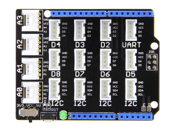
Power Compatible
Every Grove connector has four wires, one of which is the VCC. However, not every controller main board needs a supply voltage of 5V, some boards only need 3.3V. That’s why now a power toggle switch was add to this version so that one can select the suitable voltage of the controller main board using via this switch.
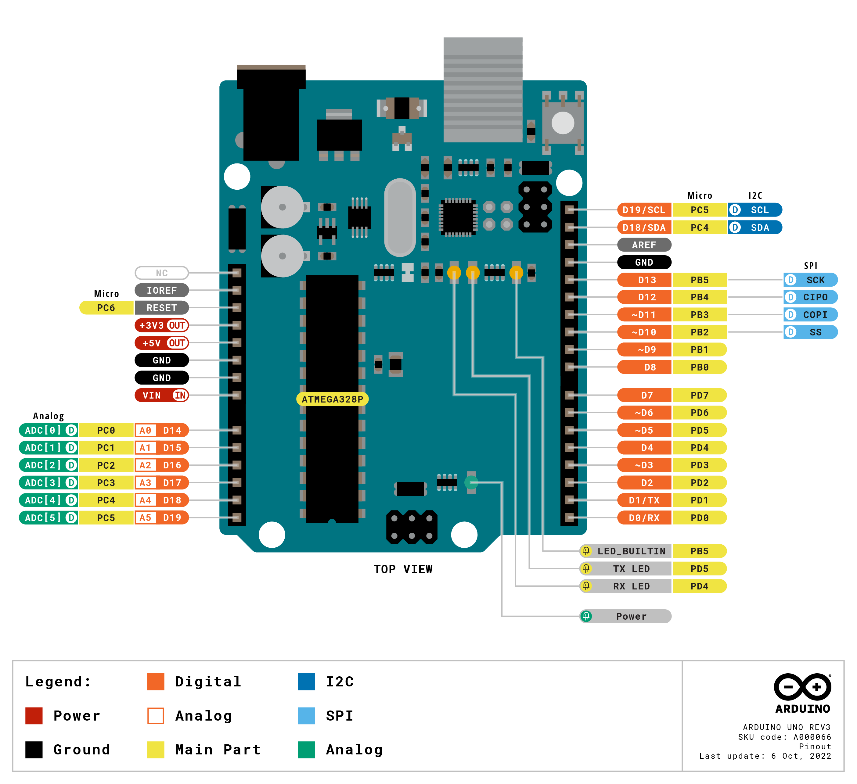
Pinout Diagram
The pinout of Base Shield V2 is the same as Arduino Uno R3 [9]. The shield usually has the same pin position as the Arduino development board and can be stacked and plugged into Arduino compatible boatds to implement specific functions.
Hardware
Name |
Function to Grove port-pin –> |
A0 |
A1 |
A2 |
A3 |
I2C |
UART |
D2 |
D3 |
D4 |
D5 |
D6 |
D7 |
D8 |
|---|---|---|---|---|---|---|---|---|---|---|---|---|---|---|
A0 |
Analog 0 / Digital 14 |
1 |
||||||||||||
A1 |
Analog 1 / Digital 15 |
2 |
1 |
|||||||||||
A2 |
Analog 2 / Digital 16 |
2 |
1 |
|||||||||||
A3 |
Analog 3 / Digital 17 |
2 |
1 |
|||||||||||
A4 |
Analog 4 / Digital 18 / I2C-SDA |
2 |
2 (*) |
|||||||||||
A5 |
Analog 5 / Digital 19 / I2C-SCL |
1 (*) |
||||||||||||
D0 |
Digital 0 / UART-RX |
1 |
||||||||||||
D1 |
Digital 1 / UART-TX |
2 |
||||||||||||
D2 |
Digital 2 (INT0) |
1 |
||||||||||||
D3 |
Digital 3 (INT1) |
2 |
1 |
|||||||||||
D4 |
Digital 4 |
2 |
1 |
|||||||||||
D5 |
Digital 5 |
2 |
1 |
|||||||||||
D6 |
Digital 6 |
2 |
1 |
|||||||||||
D7 |
Digital 7 |
2 |
1 |
|||||||||||
D8 |
Digital 8 |
2 |
1 |
|||||||||||
D9 |
Digital 9 |
2 |
||||||||||||
D10 |
Digital 10 / SPI-CS |
|||||||||||||
D11 |
Digital 11 / SPI-MOSI |
|||||||||||||
D12 |
Digital 12 / SPI-MISO |
|||||||||||||
D13 |
Digital 13 / SPI-CLK |
|||||||||||||
D18 |
Digital 18 / I2C-SDA |
2 |
||||||||||||
D19 |
Digital 19 / I2C-SCL |
1 |
(*) I2C bus default disconnected by open solder pads.
Grove Base Shield V1.3
Overview
Model: SLD01099P
The Grove Base Shield V1.3 [32] board has a similar shape to Arduino, which enables exact reflections of each I/O pins. This 1.3 version focuses on the simplicity of the interface and convenience of operation, making it even easier to use for newbies. Here is a top view:
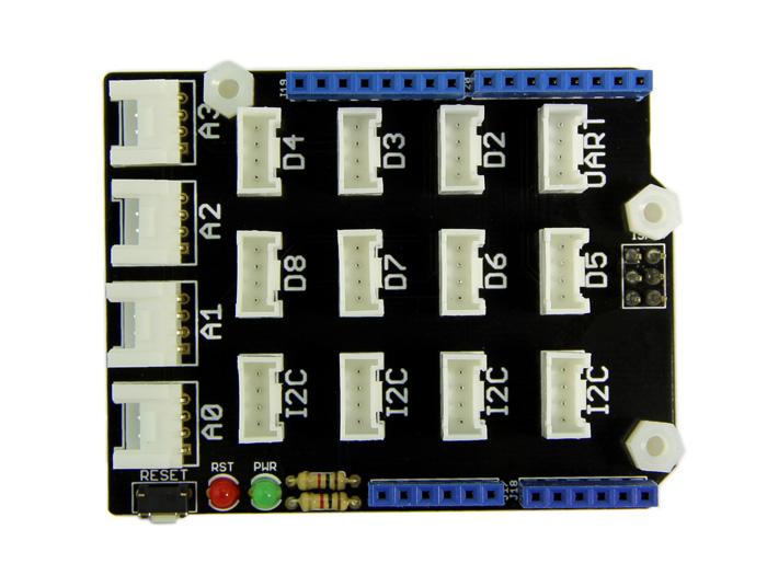
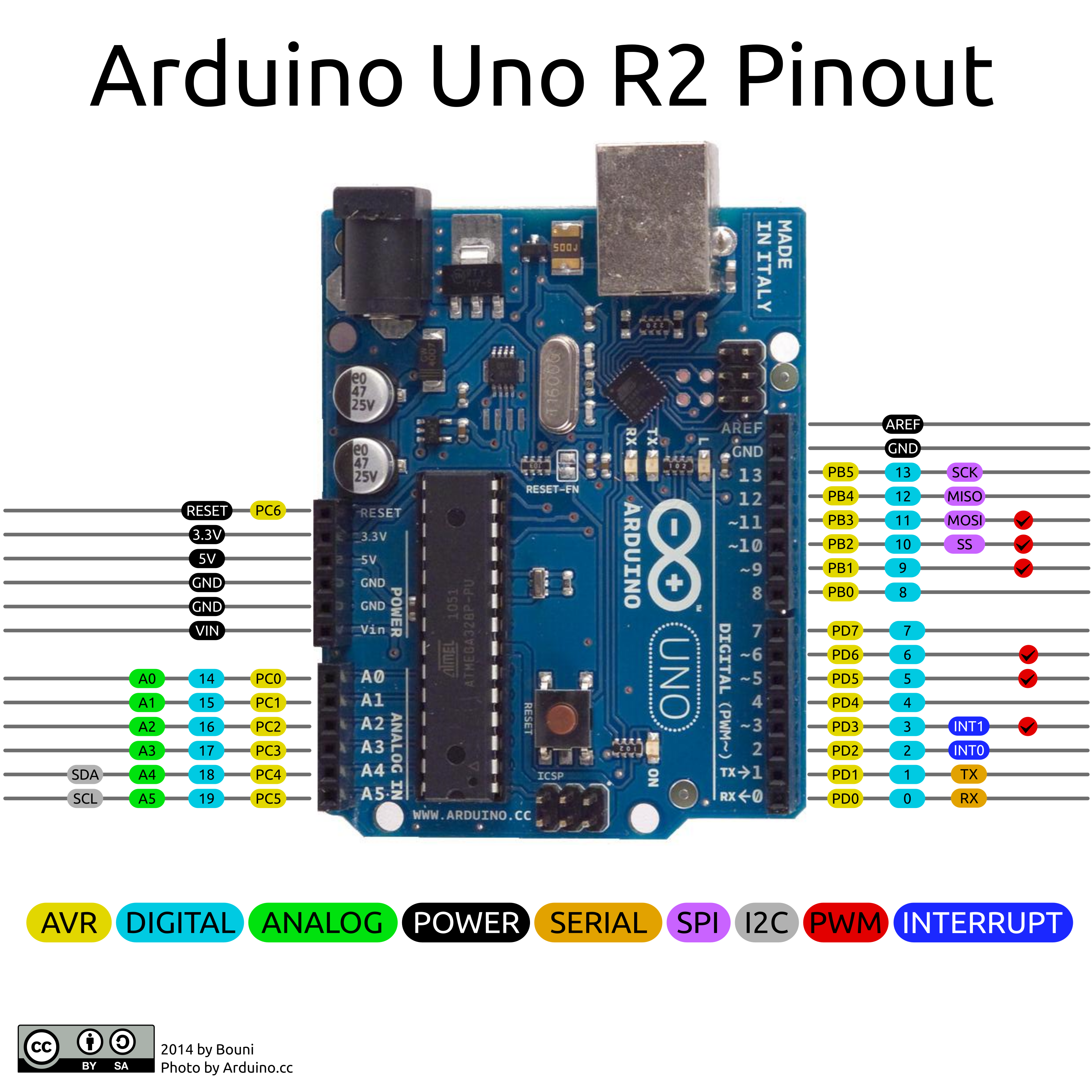
The pinout of Base Shield V1.3 is the same as Arduino Uno R2 [10].
Hardware
Name |
Function to Grove port-pin –> |
A0 |
A1 |
A2 |
A3 |
I2C |
UART |
D2 |
D3 |
D4 |
D5 |
D6 |
D7 |
D8 |
|---|---|---|---|---|---|---|---|---|---|---|---|---|---|---|
A0 |
Analog 0 / Digital 14 |
1 |
||||||||||||
A1 |
Analog 1 / Digital 15 |
2 |
1 |
|||||||||||
A2 |
Analog 2 / Digital 16 |
2 |
1 |
|||||||||||
A3 |
Analog 3 / Digital 17 |
2 |
1 |
|||||||||||
A4 |
Analog 4 / Digital 18 / I2C-SDA |
2 |
2 |
|||||||||||
A5 |
Analog 5 / Digital 19 / I2C-SCL |
1 |
||||||||||||
D0 |
Digital 0 / UART-RX |
1 |
||||||||||||
D1 |
Digital 1 / UART-TX |
2 |
||||||||||||
D2 |
Digital 2 (INT0) |
1 |
||||||||||||
D3 |
Digital 3 (INT1) |
2 |
1 |
|||||||||||
D4 |
Digital 4 |
2 |
1 |
|||||||||||
D5 |
Digital 5 |
2 |
1 |
|||||||||||
D6 |
Digital 6 |
2 |
1 |
|||||||||||
D7 |
Digital 7 |
2 |
1 |
|||||||||||
D8 |
Digital 8 |
2 |
1 |
|||||||||||
D9 |
Digital 9 |
2 |
||||||||||||
D10 |
Digital 10 |
|||||||||||||
D11 |
Digital 11 |
|||||||||||||
D12 |
Digital 12 |
|||||||||||||
D13 |
Digital 13 |
Grove Base Shield V1.2
Overview
Model: SLD12148P
The initial Grove Base Shield V1.2 [35] board is very similar in fashion to an Arduino shield board. Here is a top view:
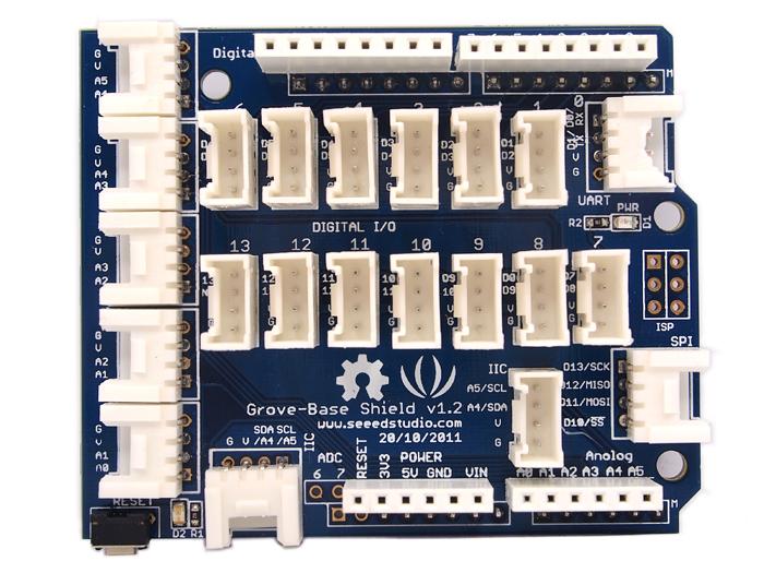
The pinout of Base Shield V1.2 is the same as Arduino Uno R2 [10].
Hardware
Name |
Function to Grove port-pin –> |
A0 |
A1 |
A2 |
A3 |
A4 |
IIC |
UART/D0 |
D1 |
D2 |
D3 |
D4 |
D5 |
D6 |
D7 |
D8 |
D9 |
D10 |
D11 |
D12 |
D13 |
SPI |
|---|---|---|---|---|---|---|---|---|---|---|---|---|---|---|---|---|---|---|---|---|---|---|
A0 |
Analog 0 / Digital 14 |
1 |
||||||||||||||||||||
A1 |
Analog 1 / Digital 15 |
2 |
1 |
|||||||||||||||||||
A2 |
Analog 2 / Digital 16 |
2 |
1 |
|||||||||||||||||||
A3 |
Analog 3 / Digital 17 |
2 |
1 |
|||||||||||||||||||
A4 |
Analog 4 / Digital 18 / I2C-SDA |
2 |
1 |
2 |
||||||||||||||||||
A5 |
Analog 5 / Digital 19 / I2C-SCL |
2 |
1 |
|||||||||||||||||||
D0 |
Digital 0 / UART-RX |
1 |
||||||||||||||||||||
D1 |
Digital 1 / UART-TX |
2 |
1 |
|||||||||||||||||||
D2 |
Digital 2 (INT0) |
2 |
1 |
|||||||||||||||||||
D3 |
Digital 3 (INT1) |
2 |
1 |
|||||||||||||||||||
D4 |
Digital 4 |
2 |
1 |
|||||||||||||||||||
D5 |
Digital 5 |
2 |
1 |
|||||||||||||||||||
D6 |
Digital 6 |
2 |
1 |
|||||||||||||||||||
D7 |
Digital 7 |
2 |
1 |
|||||||||||||||||||
D8 |
Digital 8 |
2 |
1 |
|||||||||||||||||||
D9 |
Digital 9 |
2 |
1 |
|||||||||||||||||||
D10 |
Digital 10 / SPI-CS |
2 |
1 |
4 |
||||||||||||||||||
D11 |
Digital 11 / SPI-MOSI |
2 |
1 |
3 |
||||||||||||||||||
D12 |
Digital 12 / SPI-MISO |
2 |
1 |
2 |
||||||||||||||||||
D13 |
Digital 13 / SPI-CLK |
2 |
1 |
1 |
Grove Base Shield for XIAO
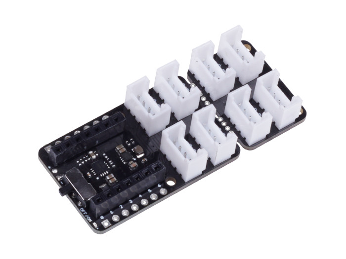
The Grove Base Shield for XIAO [37] is a plug-and-play Grove extension board that breaks out the Seeed Studio XIAO [14] pins to Grove connectors. Once you plug the Base shield on a XIAO board, you will be able to plug a Grove module to one of the Grove connectors on the Base Shield. All I/O ports of the XIAO board are exposed and adapted into Grove connectors which include digital I/O, analog I/O, and specialized ports (I2C, SPI, UART).
Versions
Currently there is only one version known:
Parameter |
Base Shield for XIAO V1 |
|---|---|
Release Date |
Apr 2020 |
Operation Voltage |
3.3V / 3.7V (LiPo-Battery) |
Operation Temperature |
-40℃ to +85℃ |
Grove Connectors |
2 x 4 (breack-off) |
Digital Ports |
5 +1 (UART) +2 (I2C) |
Analog Ports |
8 (shared with digital) |
UART Ports |
1 |
I2C Ports |
2 |
SPI Ports |
1 (PCB or 2 Grove Conn.) |
- Digital Ports:
- Analog Ports:
- UART Ports:
- I2C Ports:
see Grove I2C Layout [19]
- SPI Ports:
The Grove System [15] does not specify an SPI port. The port listed here is either the Flash SPI bonding pad area on PCB bottom side or the signals shared with on the Grove connectors for D8/A8 until A10/D10.
Grove Base Shield for XIAO V1
Overview
Model: 103020312
The Grove Base Shield for XIAO V1 board provides a simple way to connect with XIAO boards. This version 1 is the first member in the Grove System to support low-cost, high-performance XIAO boards.
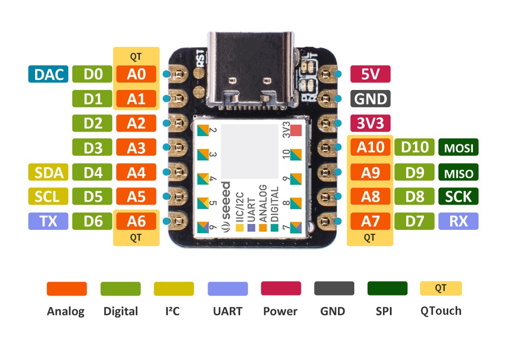
Pinout Diagram
The pinout of Base Shield V2 is the same as Seeeduino XIAO [13]. The shield usually has the same pin position as the Seeed Studio XIAO development board and will be used as an carrier board.
Hardware
Name |
Function to Grove port-pin –> |
D0 |
D1 |
D2 |
I2C |
UART |
D8 |
D9 |
|---|---|---|---|---|---|---|---|---|
D0 |
Digital 0 / Analog 0 |
1 |
||||||
D1 |
Digital 1 / Analog 1 / SPI-CS (*) |
2 |
1 |
|||||
D2 |
Digital 2 / Analog 2 |
2 |
1 |
|||||
D3 |
Digital 3 / Analog 3 |
2 |
||||||
D4 |
Digital 4 / Analog 4 / I2C-SDA |
2 |
||||||
D5 |
Digital 5 / Analog 5 / I2C-SCL |
1 |
||||||
D6 |
Digital 6 / Analog 6 / UART-TX |
2 |
||||||
D7 |
Digital 7 / Analog 7 / UART-RX |
1 |
||||||
D8 |
Digital 8 / Analog 8 / SPI-CLK |
1 |
||||||
D9 |
Digital 9 / Analog 9 / SPI-MISO |
2 |
1 |
|||||
D10 |
Digital 10 / Analog 10 / SPI-MOSI |
2 |
(*) SPI bus also connected to the SPI-Flash bonding pads.
Grove Basic Kit for Raspberry Pi Pico
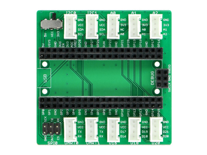
The Grove Basic Kit for Pi Pico [39] comes with an carrier board for Raspberry Pi Pico that breaks out the Raspberry Pi Pico pins to Grove connectors. Once you plug the Shield on the Raspberry Pi Pico, you will be able to plug a Grove module to one of the Grove connectors on the shield. Most of all I/O ports of the Raspberry Pi Pico are exposed and adapted into Grove connectors which include digital I/O, analog I/O, and specialized ports (I2C, SPI, UART).
Versions
Currently there is only one version known:
Parameter |
Shield for Pi Pico V1 |
|---|---|
Release Date |
Jan 2021 |
Operation Voltage |
3.3V or 5V |
Operation Temperature |
-25℃ to +85℃ |
Grove Connectors |
10 |
Digital Ports |
3 +2 (UART) +2 (I2C) |
Analog Ports |
3 |
UART Ports |
2 |
I2C Ports |
2 |
SPI Ports |
1 |
- Digital Ports:
- Analog Ports:
- UART Ports:
- I2C Ports:
see Grove I2C Layout [19]
- SPI Ports:
The Grove System [15] does not specify an SPI port. The port listed here is an simple 2x3 pin header.
Grove Shield for Pi Pico V1
Overview
Model: 103100142
The Grove Shield for Pi Pico V1 [39] board provides a simple way to connect with Raspberry Pi Pico boards. This version 1 is the first member in the Grove System to support low-cost, high-performance microcontroller RP2040 on the Raspberry Pi Pico boards, either with or without W option.
Power Compatible
Every Grove connector has four wires, one of which is the VCC. However, not every controller main board needs a supply voltage of 5V, some boards only need 3.3V. That’s why now a power toggle switch was add to this version so that one can select the suitable voltage of the controller main board using via this switch.
Pinout Diagram
The pinout of Shield for Pi Pico V1 is the same as Raspberry Pi Pico R3 [11] or Raspberry Pi Pico R3 W [12]. The shield usually has the same pin position as the Raspberry Pi Pico development board and will be used as an carrier board.
Hardware
Name |
Function to Grove port-pin –> |
UART0 |
UART1 |
I2C0 |
I2C1 |
D16 |
D18 |
D20 |
A0 |
A1 |
A2 |
|---|---|---|---|---|---|---|---|---|---|---|---|
GP0 |
Digital 0 |
2 |
|||||||||
GP1 |
Digital 1 |
1 |
|||||||||
GP2 |
Digital 2 |
||||||||||
GP3 |
Digital 3 |
||||||||||
GP4 |
Digital 4 |
2 |
|||||||||
GP5 |
Digital 5 |
1 |
|||||||||
GP6 |
Digital 6 |
2 |
|||||||||
GP7 |
Digital 7 |
1 |
|||||||||
GP8 |
Digital 8 |
2 |
|||||||||
GP9 |
Digital 9 |
1 |
|||||||||
GP10 |
Digital 10 |
||||||||||
GP11 |
Digital 11 |
||||||||||
GP12 |
Digital 12 |
||||||||||
GP13 |
Digital 13 |
||||||||||
GP14 |
Digital 14 |
||||||||||
GP15 |
Digital 15 |
||||||||||
GP16 |
Digital 16 |
1 |
|||||||||
GP17 |
Digital 17 |
2 |
|||||||||
GP18 |
Digital 18 |
1 |
|||||||||
GP19 |
Digital 19 |
2 |
|||||||||
GP20 |
Digital 20 |
1 |
|||||||||
GP21 |
Digital 21 |
2 |
|||||||||
GP22 |
Digital 22 |
||||||||||
GP23 |
(Digital 23) not on header |
||||||||||
GP24 |
(Digital 24) not on header |
||||||||||
GP25 |
(Digital 25) not on header |
||||||||||
ADC0 |
Analog 0 / Digital 26 |
1 |
2 |
||||||||
ADC1 |
Analog 1 / Digital 27 |
1 |
2 |
||||||||
ADC2 |
Analog 2 / Digital 28 |
1 |
Utilization
Laced Grove Signal Interface
All Grove Interconnect Shields provide their specific interface for general
signal mapping, the Laced Grove Signal Interface.
Following mappings are well known:
grove_gpios: GPIO mapping
grove_pwms: PWM mapping
GPIO mapping
This is the GPIO signal line mapping from an Arduino Uno R3 [9]
or Arduino Uno R2 [10] header bindet with arduino-header-r3.
Attention
On the MIMXRT1010-EVK, resistors R793, R795 and R800
must be fitted for proper use. The Laced Grove Signal Interface
overwrites the default settings of the board on the Arduino UNO R3
header and completes the missing PAD assignments for the signal
lines D4, D5 and D9.
phandle index to shield –> |
Signal : Meaning |
|
|
|---|---|---|---|
|
D0: UART-RX |
<&grove_d0_header 0 …>,<&grove_uart_header 0 …>↳
<&arduino_header 6 …> |
<&grove_d0_header 0 …>,<&grove_uart_header 0 …>↳
<&arduino_header 6 …> |
|
D1: UART-TX |
<&grove_d0_header 1 …>,<&grove_uart_header 1 …>↳
<&arduino_header 7 …> |
<&grove_d1_header 0 …>,<&grove_d0_header 1 …>,<&grove_uart_header 1 …>↳
<&arduino_header 7 …> |
|
D2 |
<&grove_d2_header 0 …>↳
<&arduino_header 8 …> |
<&grove_d2_header 0 …>,<&grove_d1_header 1 …>↳
<&arduino_header 8 …> |
|
D3 |
<&grove_d3_header 0 …>,<&grove_d2_header 1 …>↳
<&arduino_header 9 …> |
<&grove_d3_header 0 …>,<&grove_d2_header 1 …>↳
<&arduino_header 9 …> |
|
D4 |
<&grove_d4_header 0 …>,<&grove_d3_header 1 …>↳
<&arduino_header 10 …> |
<&grove_d4_header 0 …>,<&grove_d3_header 1 …>↳
<&arduino_header 10 …> |
|
D5 |
<&grove_d5_header 0 …>,<&grove_d4_header 1 …>↳
<&arduino_header 11 …> |
<&grove_d5_header 0 …>,<&grove_d4_header 1 …>↳
<&arduino_header 11 …> |
|
D6 |
<&grove_d6_header 0 …>,<&grove_d5_header 1 …>↳
<&arduino_header 12 …> |
<&grove_d6_header 0 …>,<&grove_d5_header 1 …>↳
<&arduino_header 12 …> |
|
D7 |
<&grove_d7_header 0 …>,<&grove_d6_header 1 …>↳
<&arduino_header 13 …> |
<&grove_d7_header 0 …>,<&grove_d6_header 1 …>↳
<&arduino_header 13 …> |
|
D8 |
<&grove_d8_header 0 …>,<&grove_d7_header 1 …>↳
<&arduino_header 14 …> |
<&grove_d8_header 0 …>,<&grove_d7_header 1 …>↳
<&arduino_header 14 …> |
|
D9 |
<&grove_d9_header 0 …>,<&grove_d8_header 1 …>↳
<&arduino_header 15 …> |
<&grove_d9_header 0 …>,<&grove_d8_header 1 …>↳
<&arduino_header 15 …> |
|
D10: SPI-CS |
not wired |
<&grove_d10_header 0 …>,<&grove_d9_header 1 …>,<&grove_spi_header 3 …>↳
<&arduino_header 16 …> |
|
D11: SPI-MOSI |
not wired |
<&grove_d11_header 0 …>,<&grove_d10_header 1 …>,<&grove_spi_header 2 …>↳
<&arduino_header 17 …> |
|
D12: SPI-MISO |
not wired |
<&grove_d12_header 0 …>,<&grove_d11_header 1 …>,<&grove_spi_header 1 …>↳
<&arduino_header 18 …> |
|
D13: SPI-CLK |
not wired |
<&grove_d13_header 0 …>,<&grove_d12_header 1 …>,<&grove_spi_header 0 …>↳
<&arduino_header 19 …> |
|
D14: A0 as GPIO |
<&grove_a0_header 0 …>↳
<&arduino_header 0 …> |
<&grove_a0_header 0 …>↳
<&arduino_header 0 …> |
|
D15: A1 as GPIO |
<&grove_a1_header 0 …>,<&grove_a0_header 1 …>↳
<&arduino_header 1 …> |
<&grove_a1_header 0 …>,<&grove_a0_header 1 …>↳
<&arduino_header 1 …> |
|
D16: A2 as GPIO |
<&grove_a2_header 0 …>,<&grove_a1_header 1 …>↳
<&arduino_header 2 …> |
<&grove_a2_header 0 …>,<&grove_a1_header 1 …>↳
<&arduino_header 2 …> |
|
D17: A3 as GPIO |
<&grove_a3_header 0 …>,<&grove_a2_header 1 …>↳
<&arduino_header 3 …> |
<&grove_a3_header 0 …>,<&grove_a2_header 1 …>↳
<&arduino_header 3 …> |
|
D18: (A4) I2C-SDA |
<&grove_i2c_header 1 …>,<&grove_a3_header 1 …>↳
<&arduino_header 4 …> |
<&grove_i2c_header 1 …>,<&grove_a4_header 0 …>,<&grove_a3_header 1 …>↳
<&arduino_header 4 …> |
|
D19: (A5) I2C-SCL |
<&grove_i2c_header 0 …>↳
<&arduino_header 5 …> |
<&grove_i2c_header 0 …>,<&grove_a4_header 1 …>↳
<&arduino_header 5 …> |
|
D20: ADC6 as GPIO |
||
|
|||
|
|||
|
|||
|
|||
|
|||
|
|||
|
|||
|
|||
|
|||
|
|||
|
This is the GPIO signal line mapping from a Seeeduino XIAO [13]
header bindet with seeed,xiao-gpio.
phandle index to shield –> |
Signal : Meaning |
|
|---|---|---|
|
D0: A0 as GPIO |
<&grove_d0_header 0 …>,↳
<&xiao_d 0 …> |
|
D1: A1 as GPIO / SPI-CS |
<&grove_d1_header 0 …>,<&grove_d0_header 1 …>↳
<&xiao_d 1 …> |
|
D2: A2 as GPIO |
<&grove_d2_header 0 …>,<&grove_d1_header 1 …>↳
<&xiao_d 2 …> |
|
D3: A3 as GPIO / SPI-CS |
<&grove_d2_header 1 …>,↳
<&xiao_d 3 …> |
|
D4: A4 as GPIO / I2C-SDA |
<&grove_i2c_header 1 …>,<&grove_d5_header 1 …>↳
<&xiao_d 4 …> |
|
D5: A5 as GPIO / I2C-SCL |
<&grove_i2c_header 0 …>,<&grove_d5_header 0 …>↳
<&xiao_d 5 …> |
|
D6: A6 as GPIO / UART-TX |
<&grove_uart_header 1 …>,<&grove_d7_header 1 …>↳
<&xiao_d 6 …> |
|
D7: A7 as GPIO / UART-RX (SPI-CS) |
<&grove_uart_header 0 …>,<&grove_d7_header 0 …>↳
<&xiao_d 7 …> |
|
D8: A8 as GPIO / SPI-CLK |
<&grove_d8_header 0 …>,↳
<&xiao_d 8 …> |
|
D9: A9 as GPIO / SPI-MISO |
<&grove_d9_header 0 …>,<&grove_d8_header 1 …>↳
<&xiao_d 9 …> |
|
D10: A10 as GPIO / SPI-MOSI |
<&grove_d9_header 1 …>,↳
<&xiao_d 10 …> |
|
||
|
||
|
||
|
||
|
||
|
||
|
||
|
||
|
||
|
||
|
||
|
||
|
||
|
||
|
||
|
||
|
||
|
||
|
||
|
||
|
This is the GPIO signal line mapping from a Raspberry Pi Pico R3 [11]
or Raspberry Pi Pico R3 W [12] header bindet with
raspberrypi,pico-header-r3.
In combination with some very few boards, such as the RP2040-ETH from Waveshare, not all signals are connected due to the reduced number of pins. The shield cannot account for this limitation. All connections are always available on the shield side and are mapped accordingly, but in these very rare combinations, missing connections from shield to board connectors lead to missing functionalities solely in hardware. You need to know that. Boards affected by this are included in the last columns as a special case.
phandle index to shield –> |
Signal : Meaning |
|
|
|---|---|---|---|
|
GP0: UART0-TX |
<&grove_uart0_header 1 …>,<&grove_d1_header 1 …>↳
<&rpipico_header 0 …> |
<&grove_uart0_header 1 …>,<&grove_d1_header 1 …>↳
<&rpipico_header 0 …> |
|
GP1: UART0-RX |
<&grove_uart0_header 0 …>,<&grove_d1_header 0 …>↳
<&rpipico_header 1 …> |
<&grove_uart0_header 0 …>,<&grove_d1_header 0 …>↳
<&rpipico_header 1 …> |
|
GP2: SPI0-CLK |
<&generic_spi_header 3 …>↳
<&rpipico_header 2 …> |
<&generic_spi_header 3 …>↳
<&rpipico_header 2 …> |
|
GP3: SPI0-MOSI |
<&generic_spi_header 2 …>↳
<&rpipico_header 3 …> |
<&generic_spi_header 2 …>↳
<&rpipico_header 3 …> |
|
GP4: UART1-TX / SPI0-MISO |
<&grove_uart1_header 1 …>,<&generic_spi_header 1 …>,<&grove_d5_header 1 …>↳
<&rpipico_header 4 …> |
<&grove_uart1_header 1 …>,<&generic_spi_header 1 …>,<&grove_d5_header 1 …>↳
<&rpipico_header 4 …> |
|
GP5: UART1-RX / SPI0-CS |
<&grove_uart1_header 0 …>,<&generic_spi_header 0 …>,<&grove_d5_header 0 …>↳
<&rpipico_header 5 …> |
<&grove_uart1_header 0 …>,<&generic_spi_header 0 …>,<&grove_d5_header 0 …>↳
<&rpipico_header 5 …> |
|
GP6: I2C1-SDA |
<&grove_i2c1_header 1 …><&grove_d7_header 1 …>↳
<&rpipico_header 6 …> |
<&grove_i2c1_header 1 …><&grove_d7_header 1 …>↳
<&rpipico_header 6 …> |
|
GP7: I2C1-SCL |
<&grove_i2c1_header 0 …><&grove_d7_header 0 …>↳
<&rpipico_header 7 …> |
<&grove_i2c1_header 0 …><&grove_d7_header 0 …>↳
<&rpipico_header 7 …> |
|
GP8: I2C0-SDA |
<&grove_i2c0_header 1 …><&grove_d9_header 1 …>↳
<&rpipico_header 8 …> |
<&grove_i2c0_header 1 …><&grove_d9_header 1 …>↳
<&rpipico_header 8 …> |
|
GP9: I2C0-SCL |
<&grove_i2c0_header 0 …><&grove_d9_header 0 …>↳
<&rpipico_header 9 …> |
<&grove_i2c0_header 0 …><&grove_d9_header 0 …>↳
<&rpipico_header 9 …> |
|
GP10 |
not wired |
not wired |
|
GP11 |
not wired |
not wired |
|
GP12 |
not wired |
not wired |
|
GP13 |
not wired |
not wired |
|
GP14 |
not wired |
not wired |
|
GP15 |
not wired |
not wired |
|
GP16 |
<&grove_d16_header 0 …>↳
<&rpipico_header 16 …> |
not wired |
|
GP17 |
<&grove_d16_header 1 …>↳
<&rpipico_header 17 …> |
internal wired
ETH-TCPCS
|
|
GP18 |
<&grove_d18_header 0 …>↳
<&rpipico_header 18 …> |
internal wired
ETH-CFG0
|
|
GP19 |
<&grove_d18_header 1 …>↳
<&rpipico_header 19 …> |
internal wired
ETH-RSTI
|
|
GP20 |
<&grove_d20_header 0 …>↳
<&rpipico_header 20 …> |
internal wired
ETH-RX (UART1-TX)
|
|
GP21 |
<&grove_d20_header 1 …>↳
<&rpipico_header 21 …> |
internal wired
ETH-TX (UART1-RX)
|
|
GP22 |
not wired |
not wired |
|
GP23: not on header / SMPS |
not wired |
not wired |
|
GP24: not on header / VBUS |
not wired |
not wired |
|
GP25: not on header / LED |
not wired |
not wired |
|
GP26: ADC0 as GPIO |
<&grove_a0_header 0 …>↳
<&rpipico_header 26 …> |
<&grove_a0_header 0 …>↳
<&rpipico_header 26 …> |
|
GP27: ADC1 as GPIO |
<&grove_a1_header 0 …>↳
<&rpipico_header 27 …> |
<&grove_a1_header 0 …>↳
<&rpipico_header 27 …> |
|
GP28: ADC2 as GPIO |
<&grove_a2_header 0 …>↳
<&rpipico_header 28 …> |
<&grove_a2_header 0 …>↳
<&rpipico_header 28 …> |
|
GP29: ADC3 as GPIO / VSYS |
not wired |
not wired |
|
|||
|
PWM mapping
Not all boards provide a dedicated PWM channel for the output of a variable average value of voltage or current over time on all digital lines. The corresponding mapping is always board or SOC specific. In addition to the PWM signal line mapping, the valid references to the PWM function units in the SOC or on the board are therefore also defined as Grove PWM Labels.
The following tables reflects the currently supported boards, but this list will be growing up with further development and maintenance. This list must not be complete.
This is based on the Bridle extended board
Nucleo F303RE (BBE) and its
arduino-header-r3.
Grove PWM Label |
phandle index to shield –> |
Signal : Meaning |
|
|
|---|---|---|---|---|
|
D0: UART-RX |
|||
|
D1: UART-TX |
|||
|
|
D2 |
|
|
|
|
D3 |
|
|
|
|
D4 |
|
|
|
|
D5 |
|
|
|
|
D6 |
|
|
|
|
D7 |
|
|
|
|
D8 |
|
|
|
|
D9 |
|
|
|
|
D10: SPI-CS |
not wired |
|
|
|
D11: SPI-MOSI |
not wired |
|
|
|
D12: SPI-MISO |
not wired |
|
|
|
D13: SPI-CLK |
not wired |
|
|
D14: A0 |
|||
|
D15: A1 |
|||
|
D16: A2 |
|||
|
D17: A3 |
|||
|
|
D18: (A4) I2C-SDA |
|
|
|
|
D19: (A5) I2C-SCL |
|
|
|
D20: ADC6 |
|||
|
||||
|
||||
|
||||
|
||||
|
||||
|
||||
|
||||
|
||||
|
||||
|
||||
|
This is based on the Bridle extended board
Nucleo F401RE (BBE) and its
arduino-header-r3.
Grove PWM Label |
phandle index to shield –> |
Signal : Meaning |
|
|
|---|---|---|---|---|
|
D0: UART-RX |
|||
|
D1: UART-TX |
|||
|
|
D2 |
|
|
|
|
D3 |
|
|
|
D4 |
|||
|
|
D5 |
|
|
|
|
D6 |
|
|
|
|
D7 |
|
|
|
|
D8 |
|
|
|
|
D9 |
|
|
|
|
D10: SPI-CS |
not wired |
|
|
|
D11: SPI-MOSI |
not wired |
|
|
D12: SPI-MISO |
not wired |
||
|
|
D13: SPI-CLK |
not wired |
|
|
D14: A0 |
|||
|
D15: A1 |
|||
|
D16: A2 |
|||
|
D17: A3 |
|||
|
|
D18: (A4) I2C-SDA |
|
|
|
|
D19: (A5) I2C-SCL |
|
|
|
D20: ADC6 |
|||
|
||||
|
||||
|
||||
|
||||
|
||||
|
||||
|
||||
|
||||
|
||||
|
||||
|
This is based on the Zephyr board Nucleo F413ZH
or the Bridle extended board Nucleo F413ZH (BBE)
and its arduino-header-r3.
Grove PWM Label |
phandle index to shield –> |
Signal : Meaning |
|
|
|---|---|---|---|---|
|
D0: UART-RX |
|||
|
D1: UART-TX |
|||
|
D2 |
|||
|
|
D3 |
|
|
|
D4 |
|||
|
|
D5 |
|
|
|
|
D6 |
|
|
|
D7 |
|||
|
D8 |
|||
|
|
D9 |
|
|
|
|
D10: SPI-CS |
not wired |
|
|
|
D11: SPI-MOSI |
not wired |
|
|
|
D12: SPI-MISO |
not wired |
|
|
|
D13: SPI-CLK |
not wired |
|
|
D14: A0 |
|||
|
D15: A1 |
|||
|
D16: A2 |
|||
|
D17: A3 |
|||
|
|
D18: (A4) I2C-SDA |
|
|
|
|
D19: (A5) I2C-SCL |
|
|
|
D20: ADC6 |
|||
|
||||
|
||||
|
||||
|
||||
|
||||
|
||||
|
||||
|
||||
|
||||
|
||||
|
This is based on the Zephyr board Nucleo F746ZG
or the Bridle extended board Nucleo F746ZG (BBE)
and its arduino-header-r3.
Grove PWM Label |
phandle index to shield –> |
Signal : Meaning |
|
|
|---|---|---|---|---|
|
D0: UART-RX |
|||
|
D1: UART-TX |
|||
|
D2 |
|||
|
|
D3 |
|
|
|
D4 |
|||
|
|
D5 |
|
|
|
|
D6 |
|
|
|
D7 |
|||
|
D8 |
|||
|
|
D9 |
|
|
|
|
D10: SPI-CS |
not wired |
|
|
|
D11: SPI-MOSI |
not wired |
|
|
|
D12: SPI-MISO |
not wired |
|
|
|
D13: SPI-CLK |
not wired |
|
|
D14: A0 |
|||
|
D15: A1 |
|||
|
D16: A2 |
|||
|
D17: A3 |
|||
|
|
D18: (A4) I2C-SDA |
|
|
|
|
D19: (A5) I2C-SCL |
|
|
|
D20: ADC6 |
|||
|
||||
|
||||
|
||||
|
||||
|
||||
|
||||
|
||||
|
||||
|
||||
|
||||
|
This is based on the Zephyr board Nucleo F767ZI
or the Bridle extended board Nucleo F767ZI (BBE)
and its arduino-header-r3.
Grove PWM Label |
phandle index to shield –> |
Signal : Meaning |
|
|
|---|---|---|---|---|
|
D0: UART-RX |
|||
|
D1: UART-TX |
|||
|
D2 |
|||
|
|
D3 |
|
|
|
D4 |
|||
|
|
D5 |
|
|
|
|
D6 |
|
|
|
D7 |
|||
|
D8 |
|||
|
|
D9 |
|
|
|
|
D10: SPI-CS |
not wired |
|
|
|
D11: SPI-MOSI |
not wired |
|
|
|
D12: SPI-MISO |
not wired |
|
|
|
D13: SPI-CLK |
not wired |
|
|
D14: A0 |
|||
|
D15: A1 |
|||
|
D16: A2 |
|||
|
D17: A3 |
|||
|
|
D18: (A4) I2C-SDA |
|
|
|
|
D19: (A5) I2C-SCL |
|
|
|
D20: ADC6 |
|||
|
||||
|
||||
|
||||
|
||||
|
||||
|
||||
|
||||
|
||||
|
||||
|
||||
|
This is based on the Bridle extended board
MIMXRT1010-EVK (BBE) and its
arduino-header-r3.
Note
This board shares many signals on this Laced Grove Signal Interface
with other on-board function units, e.g. audio codec and sensors or
the SPI Flash (when populated). Check your current board configuration
with the hardware user manual and/or schematic if you need to change
jumper or solder bridge setups for proper usage.
Attention
On the MIMXRT1010-EVK, resistors R793, R795 and R800
must be fitted for proper use. The Laced Grove Signal Interface
overwrites the default settings of the board on the Arduino UNO R3
header and completes the missing PAD assignments for the signal
lines D4, D5 and D9.
Grove PWM Label |
phandle index to shield –> |
Signal : Meaning |
|
|
|---|---|---|---|---|
|
D0: UART-RX |
|||
|
D1: UART-TX |
|||
|
D2 |
|||
|
D3 |
|||
|
D4 |
|||
|
D5 |
|||
|
D6 |
|||
|
D7 |
|||
|
|
D8 |
|
|
|
|
D9 |
|
|
|
D10: SPI-CS |
not wired |
||
|
D11: SPI-MOSI |
not wired |
||
|
D12: SPI-MISO |
not wired |
||
|
D13: SPI-CLK |
not wired |
||
|
D14: A0 |
|||
|
D15: A1 |
|||
|
D16: A2 |
|||
|
D17: A3 |
|||
|
D18: (A4) I2C-SDA |
|||
|
D19: (A5) I2C-SCL |
|||
|
D20: ADC6 |
|||
|
||||
|
||||
|
||||
|
||||
|
||||
|
||||
|
||||
|
||||
|
||||
|
||||
|
This is based on the Zephyr board MIMXRT1060-EVK
or the Bridle extended board MIMXRT1060-EVK (BBE)
and its arduino-header-r3.
Note
This board shares many signals on this Laced Grove Signal Interface
with other on-board function units, e.g. camera and display or the
M.2 and TF/SD-Card connectors. Check your current board configuration
with the hardware user manual and/or schematic if you need to change
jumper or solder bridge setups for proper usage.
Grove PWM Label |
phandle index to shield –> |
Signal : Meaning |
|
|
|---|---|---|---|---|
|
D0: UART-RX |
|||
|
D1: UART-TX |
|||
|
|
D2 |
|
|
|
|
D3 |
|
|
|
|
D4 |
|
|
|
|
D5 |
|
|
|
D6 |
|||
|
D7 |
|||
|
D8 |
|||
|
D9 |
|||
|
|
D10: SPI-CS |
not wired |
|
|
|
D11: SPI-MOSI |
not wired |
|
|
|
D12: SPI-MISO |
not wired |
|
|
|
D13: SPI-CLK |
not wired |
|
|
D14: A0 |
|||
|
D15: A1 |
|||
|
D16: A2 |
|||
|
D17: A3 |
|||
|
D18: (A4) I2C-SDA |
|||
|
D19: (A5) I2C-SCL |
|||
|
D20: ADC6 |
|||
|
||||
|
||||
|
||||
|
||||
|
||||
|
||||
|
||||
|
||||
|
||||
|
||||
|
This is based on the Bridle extended board
Arduino/Genuino Zero (BBE) and its
arduino-header-r3.
Note
This board basically provides all channels from all timers as PWM to
the outside. However, the SoC’s ability to route channels to multiple
pads may result in channels being connected in parallel. The second
table below shows the possibilities which channels can really
be used independently at the associated signals of the
Laced Grove Signal Interface.
Grove PWM Label |
phandle index to shield –> |
Signal : Meaning |
|
|
|---|---|---|---|---|
|
|
D0: UART-RX |
|
|
|
|
D1: UART-TX |
|
|
|
|
D2 |
|
|
|
|
D3 |
|
|
|
|
D4 |
|
|
|
|
D5 |
|
|
|
|
D6 |
|
|
|
|
D7 |
|
|
|
|
D8 |
|
|
|
|
D9 |
|
|
|
|
D10: SPI-CS |
not wired |
|
|
|
D11: SPI-MOSI |
not wired |
|
|
|
D12: SPI-MISO |
not wired |
|
|
|
D13: SPI-CLK |
not wired |
|
|
D14: A0 |
|||
|
D15: A1 |
|||
|
D16: A2 |
|||
|
D17: A3 |
|||
|
|
D18: (A4) I2C-SDA |
|
|
|
|
D19: (A5) I2C-SCL |
|
|
|
D20: ADC6 |
|||
|
||||
|
||||
|
||||
|
||||
|
||||
|
||||
|
||||
|
||||
|
||||
|
||||
|
Signal : Meaning |
TCC0 |
TCC1 |
TCC2 |
|||||
|---|---|---|---|---|---|---|---|---|
CH0 |
CH1 |
CH2 |
CH3 |
CH0 |
CH1 |
CH0 |
CH1 |
|
D0: UART-RX |
WO3 |
|||||||
D1: UART-TX |
WO2 |
|||||||
D2 |
WO4 |
|||||||
D3 |
WO1 |
|||||||
D4 |
WO0 |
|||||||
D5 |
WO5 |
|||||||
D6 |
WO6 |
|||||||
D7 |
WO7 |
|||||||
D8 |
WO0 |
|||||||
D9 |
WO1 |
|||||||
D10: SPI-CS |
WO2 |
|||||||
D11: SPI-MOSI |
WO0 |
|||||||
D12: SPI-MISO |
WO3 |
|||||||
D13: SPI-CLK |
WO1 |
|||||||
D14: A0 |
||||||||
D15: A1 |
||||||||
D16: A2 |
||||||||
D17: A3 |
||||||||
D18: (A4) I2C-SDA |
WO4 |
|||||||
D19: (A5) I2C-SCL |
WO5 |
|||||||
D20: ADC6 |
||||||||
This is based on the Bridle board Seeeduino Cortex-M0+
and its arduino-header-r3.
Note
This board basically provides all channels from all timers as PWM to
the outside. However, the SoC’s ability to route channels to multiple
pads may result in channels being connected in parallel. The second
table below shows the possibilities which channels can really
be used independently at the associated signals of the
Laced Grove Signal Interface.
Grove PWM Label |
phandle index to shield –> |
Signal : Meaning |
|
|
|---|---|---|---|---|
|
|
D0: UART-RX |
|
|
|
|
D1: UART-TX |
|
|
|
|
D2 |
|
|
|
|
D3 |
|
|
|
|
D4 |
|
|
|
|
D5 |
|
|
|
|
D6 |
|
|
|
|
D7 |
|
|
|
|
D8 |
|
|
|
|
D9 |
|
|
|
|
D10: SPI-CS |
not wired |
|
|
|
D11: SPI-MOSI |
not wired |
|
|
|
D12: SPI-MISO |
not wired |
|
|
|
D13: SPI-CLK |
not wired |
|
|
D14: A0 |
|||
|
D15: A1 |
|||
|
D16: A2 |
|||
|
D17: A3 |
|||
|
|
D18: (A4) I2C-SDA |
|
|
|
|
D19: (A5) I2C-SCL |
|
|
|
D20: ADC6 |
|||
|
||||
|
||||
|
||||
|
||||
|
||||
|
||||
|
||||
|
||||
|
||||
|
||||
|
Signal : Meaning |
TCC0 |
TCC1 |
TCC2 |
|||||
|---|---|---|---|---|---|---|---|---|
CH0 |
CH1 |
CH2 |
CH3 |
CH0 |
CH1 |
CH0 |
CH1 |
|
D0: UART-RX |
WO3 |
|||||||
D1: UART-TX |
WO2 |
|||||||
D2 |
WO4 |
|||||||
D3 |
WO1 |
|||||||
D4 |
WO0 |
|||||||
D5 |
WO5 |
|||||||
D6 |
WO6 |
|||||||
D7 |
WO7 |
|||||||
D8 |
WO0 |
|||||||
D9 |
WO1 |
|||||||
D10: SPI-CS |
WO2 |
|||||||
D11: SPI-MOSI |
WO0 |
|||||||
D12: SPI-MISO |
WO3 |
|||||||
D13: SPI-CLK |
WO1 |
|||||||
D14: A0 |
||||||||
D15: A1 |
||||||||
D16: A2 |
||||||||
D17: A3 |
||||||||
D18: (A4) I2C-SDA |
WO4 |
|||||||
D19: (A5) I2C-SCL |
WO5 |
|||||||
D20: ADC6 |
||||||||
This is based on the Bridle board Seeeduino Lotus Cortex-M0+
and its arduino-header-r3.
Note
This board basically provides all channels from all timers as PWM to
the outside. However, the SoC’s ability to route channels to multiple
pads may result in channels being connected in parallel. The second
table below shows the possibilities which channels can really
be used independently at the associated signals of the
Laced Grove Signal Interface.
Grove PWM Label |
phandle index to shield –> |
Signal : Meaning |
|
|
|---|---|---|---|---|
|
|
D0: UART-RX |
|
|
|
|
D1: UART-TX |
|
|
|
|
D2 |
|
|
|
|
D3 |
|
|
|
|
D4 |
|
|
|
|
D5 |
|
|
|
|
D6 |
|
|
|
|
D7 |
|
|
|
|
D8 |
|
|
|
|
D9 |
|
|
|
|
D10: SPI-CS |
not wired |
|
|
|
D11: SPI-MOSI |
not wired |
|
|
|
D12: SPI-MISO |
not wired |
|
|
|
D13: SPI-CLK |
not wired |
|
|
D14: A0 |
|||
|
D15: A1 |
|||
|
D16: A2 |
|||
|
D17: A3 |
|||
|
|
D18: (A4) I2C-SDA |
|
|
|
|
D19: (A5) I2C-SCL |
|
|
|
D20: ADC6 |
|||
|
||||
|
||||
|
||||
|
||||
|
||||
|
||||
|
||||
|
||||
|
||||
|
||||
|
Signal : Meaning |
TCC0 |
TCC1 |
TCC2 |
|||||
|---|---|---|---|---|---|---|---|---|
CH0 |
CH1 |
CH2 |
CH3 |
CH0 |
CH1 |
CH0 |
CH1 |
|
D0: UART-RX |
WO3 |
|||||||
D1: UART-TX |
WO2 |
|||||||
D2 |
WO4 |
|||||||
D3 |
WO1 |
|||||||
D4 |
WO0 |
|||||||
D5 |
WO5 |
|||||||
D6 |
WO6 |
|||||||
D7 |
WO7 |
|||||||
D8 |
WO0 |
|||||||
D9 |
WO1 |
|||||||
D10: SPI-CS |
WO2 |
|||||||
D11: SPI-MOSI |
WO0 |
|||||||
D12: SPI-MISO |
WO3 |
|||||||
D13: SPI-CLK |
WO1 |
|||||||
D14: A0 |
||||||||
D15: A1 |
||||||||
D16: A2 |
||||||||
D17: A3 |
||||||||
D18: (A4) I2C-SDA |
WO4 |
|||||||
D19: (A5) I2C-SCL |
WO5 |
|||||||
D20: ADC6 |
||||||||
This is based on the Zephyr board Seeeduino XIAO
or the Bridle extended board Seeeduino XIAO (BBE)
and its seeed,xiao-gpio.
Note
This board basically provides only some channels from a few timers as
PWM to the outside. The SoC’s ability to route channels to multiple
pads may result in channels being connected in parallel. The second
table below shows the possibilities which channels can really
be used independently at the associated signals of the
Laced Grove Signal Interface.
Grove PWM Label |
phandle index to shield –> |
Signal : Meaning |
|
|---|---|---|---|
|
D0 |
not possible |
|
|
|
D1: SPI-CS |
|
|
|
D2 |
|
|
|
D3 |
|
|
|
D4: I2C-SDA |
|
|
|
D5: I2C-SCL |
|
|
D6: UART-TX |
not possible |
|
|
D7: UART-RX |
not possible |
|
|
|
D8: SPI-CLK |
|
|
|
D9: SPI-MISO |
|
|
|
D10: SPI-MOSI |
|
|
|||
|
|||
|
|||
|
|||
|
|||
|
|||
|
|||
|
|||
|
|||
|
|||
|
|||
|
|||
|
|||
|
|||
|
|||
|
|||
|
|||
|
|||
|
|||
|
|||
|
Signal : Meaning |
TCC0 |
TCC1 |
TCC2 |
|||||
|---|---|---|---|---|---|---|---|---|
CH0 |
CH1 |
CH2 |
CH3 |
CH0 |
CH1 |
CH0 |
CH1 |
|
D0 |
||||||||
D1: SPI-CS |
WO0 |
|||||||
D2 |
WO2 |
|||||||
D3 |
WO3 |
|||||||
D4: I2C-SDA |
WO0 |
|||||||
D5: I2C-SCL |
WO1 |
|||||||
D6: UART-TX |
||||||||
D7: UART-RX |
||||||||
D8: SPI-CLK |
WO1 |
|||||||
D9: SPI-MISO |
WO1 |
|||||||
D10: SPI-MOSI |
WO0 |
|||||||
This is based on the Bridle board XIAO SAMD21 (Seeeduino XIAO)
and its seeed,xiao-gpio.
Note
This board basically provides only some channels from a few timers as
PWM to the outside. The SoC’s ability to route channels to multiple
pads may result in channels being connected in parallel. The second
table below shows the possibilities which channels can really
be used independently at the associated signals of the
Laced Grove Signal Interface.
Grove PWM Label |
phandle index to shield –> |
Signal : Meaning |
|
|---|---|---|---|
|
D0 |
not possible |
|
|
|
D1: SPI-CS |
|
|
|
D2 |
|
|
|
D3 |
|
|
|
D4: I2C-SDA |
|
|
|
D5: I2C-SCL |
|
|
D6: UART-TX |
not possible |
|
|
D7: UART-RX |
not possible |
|
|
|
D8: SPI-CLK |
|
|
|
D9: SPI-MISO |
|
|
|
D10: SPI-MOSI |
|
|
|||
|
|||
|
|||
|
|||
|
|||
|
|||
|
|||
|
|||
|
|||
|
|||
|
|||
|
|||
|
|||
|
|||
|
|||
|
|||
|
|||
|
|||
|
|||
|
|||
|
Signal : Meaning |
TCC0 |
TCC1 |
TCC2 |
|||||
|---|---|---|---|---|---|---|---|---|
CH0 |
CH1 |
CH2 |
CH3 |
CH0 |
CH1 |
CH0 |
CH1 |
|
D0 |
||||||||
D1: SPI-CS |
WO0 |
|||||||
D2 |
WO2 |
|||||||
D3 |
WO3 |
|||||||
D4: I2C-SDA |
WO0 |
|||||||
D5: I2C-SCL |
WO1 |
|||||||
D6: UART-TX |
||||||||
D7: UART-RX |
||||||||
D8: SPI-CLK |
WO1 |
|||||||
D9: SPI-MISO |
WO1 |
|||||||
D10: SPI-MOSI |
WO0 |
|||||||
This is based on the Bridle extended board
Raspberry Pi Pico 2 (BBE) and its
raspberrypi,pico-header-r3.
Note
This board basically provides all channels from nearly all PWMs to
the outside. However, the SoC’s ability to route channels to multiple
pads may result in channels being connected in parallel. The second
table below shows the possibilities which channels can really
be used independently at the associated signals of the
Laced Grove Signal Interface.
Grove PWM Label |
phandle index to shield –> |
Signal : Meaning |
|
|---|---|---|---|
|
GP0: UART0-TX |
not possible |
|
|
GP1: UART0-RX |
not possible |
|
|
GP2: SPI0-CLK |
not possible |
|
|
GP3: SPI0-MOSI |
not possible |
|
|
GP4: UART1-TX / SPI0-MISO |
not possible |
|
|
GP5: UART1-RX / SPI0-CS |
not possible |
|
|
GP6: I2C1-SDA |
not possible |
|
|
GP7: I2C1-SCL |
not possible |
|
|
GP8: I2C0-SDA |
not possible |
|
|
GP9: I2C0-SCL |
not possible |
|
|
|
GP10: |
|
|
|
GP11: |
|
|
|
GP12: |
|
|
|
GP13: |
|
|
|
GP14: |
|
|
|
GP15: |
|
|
|
GP16: |
|
|
|
GP17: |
|
|
|
GP18: |
|
|
|
GP19: |
|
|
|
GP20: |
|
|
|
GP21: |
|
|
|
GP22: |
|
|
GP23: SMPS save |
not wired |
|
|
GP24: VBUS sense |
not wired |
|
|
|
GP25: LED |
|
|
GP26: ADC0 |
not possible |
|
|
GP27: ADC1 |
not possible |
|
|
GP28: ADC2 |
not possible |
|
|
GP29: ADC3 / VSYS/3 |
not wired |
|
|
|||
|
Signal : Meaning |
Index |
PWM |
|||||||
|---|---|---|---|---|---|---|---|---|---|
0 |
1 |
2 |
3 |
4 |
5 |
6 |
7 |
||
GP0: UART0-TX |
0 |
CHA |
|||||||
GP1: UART0-RX |
1 |
CHB |
|||||||
GP2: SPI0-CLK |
2 |
CHA |
|||||||
GP3: SPI0-MOSI |
3 |
CHB |
|||||||
GP4: UART1-TX / SPI0-MISO |
4 |
CHA |
|||||||
GP5: UART1-RX / SPI0-CS |
5 |
CHB |
|||||||
GP6: I2C1-SDA |
6 |
CHA |
|||||||
GP7: I2C1-SCL |
7 |
CHB |
|||||||
GP8: I2C0-SDA |
8 |
CHA |
|||||||
GP9: I2C0-SCL |
9 |
CHB |
|||||||
GP10: |
10 |
CHA |
|||||||
GP11: |
11 |
CHB |
|||||||
GP12: |
12 |
CHA |
|||||||
GP13: |
13 |
CHB |
|||||||
GP14: |
14 |
CHA |
|||||||
GP15: |
15 |
CHB |
|||||||
GP16: |
0 |
CHA |
|||||||
GP17: |
1 |
CHB |
|||||||
GP18: |
2 |
CHA |
|||||||
GP19: |
3 |
CHB |
|||||||
GP20: |
4 |
CHA |
|||||||
GP21: |
5 |
CHB |
|||||||
GP22: |
6 |
CHA |
|||||||
GP23: SMPS save |
7 |
CHB |
|||||||
GP24: VBUS sense |
8 |
CHA |
|||||||
GP25: LED |
9 |
CHB |
|||||||
GP26: ADC0 |
10 |
CHA |
|||||||
GP27: ADC1 |
11 |
CHB |
|||||||
GP28: ADC2 |
12 |
CHA |
|||||||
GP29: ADC3 / VSYS/3 |
13 |
CHB |
|||||||
This is based on the Bridle extended board
Raspberry Pi Pico (BBE) and its
raspberrypi,pico-header-r3.
Note
This board basically provides all channels from nearly all PWMs to
the outside. However, the SoC’s ability to route channels to multiple
pads may result in channels being connected in parallel. The second
table below shows the possibilities which channels can really
be used independently at the associated signals of the
Laced Grove Signal Interface.
Grove PWM Label |
phandle index to shield –> |
Signal : Meaning |
|
|---|---|---|---|
|
GP0: UART0-TX |
not possible |
|
|
GP1: UART0-RX |
not possible |
|
|
GP2: SPI0-CLK |
not possible |
|
|
GP3: SPI0-MOSI |
not possible |
|
|
GP4: UART1-TX / SPI0-MISO |
not possible |
|
|
GP5: UART1-RX / SPI0-CS |
not possible |
|
|
GP6: I2C1-SDA |
not possible |
|
|
GP7: I2C1-SCL |
not possible |
|
|
GP8: I2C0-SDA |
not possible |
|
|
GP9: I2C0-SCL |
not possible |
|
|
|
GP10: |
|
|
|
GP11: |
|
|
|
GP12: |
|
|
|
GP13: |
|
|
|
GP14: |
|
|
|
GP15: |
|
|
|
GP16: |
|
|
|
GP17: |
|
|
|
GP18: |
|
|
|
GP19: |
|
|
|
GP20: |
|
|
|
GP21: |
|
|
|
GP22: |
|
|
GP23: SMPS save |
not wired |
|
|
GP24: VBUS sense |
not wired |
|
|
|
GP25: LED |
|
|
GP26: ADC0 |
not possible |
|
|
GP27: ADC1 |
not possible |
|
|
GP28: ADC2 |
not possible |
|
|
GP29: ADC3 / VSYS/3 |
not wired |
|
|
|||
|
Signal : Meaning |
Index |
PWM |
|||||||
|---|---|---|---|---|---|---|---|---|---|
0 |
1 |
2 |
3 |
4 |
5 |
6 |
7 |
||
GP0: UART0-TX |
0 |
CHA |
|||||||
GP1: UART0-RX |
1 |
CHB |
|||||||
GP2: SPI0-CLK |
2 |
CHA |
|||||||
GP3: SPI0-MOSI |
3 |
CHB |
|||||||
GP4: UART1-TX / SPI0-MISO |
4 |
CHA |
|||||||
GP5: UART1-RX / SPI0-CS |
5 |
CHB |
|||||||
GP6: I2C1-SDA |
6 |
CHA |
|||||||
GP7: I2C1-SCL |
7 |
CHB |
|||||||
GP8: I2C0-SDA |
8 |
CHA |
|||||||
GP9: I2C0-SCL |
9 |
CHB |
|||||||
GP10: |
10 |
CHA |
|||||||
GP11: |
11 |
CHB |
|||||||
GP12: |
12 |
CHA |
|||||||
GP13: |
13 |
CHB |
|||||||
GP14: |
14 |
CHA |
|||||||
GP15: |
15 |
CHB |
|||||||
GP16: |
0 |
CHA |
|||||||
GP17: |
1 |
CHB |
|||||||
GP18: |
2 |
CHA |
|||||||
GP19: |
3 |
CHB |
|||||||
GP20: |
4 |
CHA |
|||||||
GP21: |
5 |
CHB |
|||||||
GP22: |
6 |
CHA |
|||||||
GP23: SMPS save |
7 |
CHB |
|||||||
GP24: VBUS sense |
8 |
CHA |
|||||||
GP25: LED |
9 |
CHB |
|||||||
GP26: ADC0 |
10 |
CHA |
|||||||
GP27: ADC1 |
11 |
CHB |
|||||||
GP28: ADC2 |
12 |
CHA |
|||||||
GP29: ADC3 / VSYS/3 |
13 |
CHB |
|||||||
This is based on the Bridle board RP2040-ETH
and its raspberrypi,pico-header-r3
with reduced connections.
Note
This board basically provides all channels from nearly all PWMs to
the outside. However, the SoC’s ability to route channels to multiple
pads may result in channels being connected in parallel. The second
table below shows the possibilities which channels can really
be used independently at the associated signals of the
Laced Grove Signal Interface.
Grove PWM Label |
phandle index to shield –> |
Signal : Meaning |
|
|---|---|---|---|
|
GP0: UART0-TX |
not possible |
|
|
GP1: UART0-RX |
not possible |
|
|
GP2: SPI0-CLK |
not possible |
|
|
GP3: SPI0-MOSI |
not possible |
|
|
GP4: UART1-TX / SPI0-MISO |
not possible |
|
|
GP5: UART1-RX / SPI0-CS |
not possible |
|
|
GP6: I2C1-SDA |
not possible |
|
|
GP7: I2C1-SCL |
not possible |
|
|
GP8: I2C0-SDA |
not possible |
|
|
GP9: I2C0-SCL |
not possible |
|
|
|
GP10: |
not wired |
|
|
GP11: |
not wired |
|
|
GP12: |
not wired |
|
|
GP13: |
not wired |
|
|
GP14: |
not wired |
|
|
GP15: |
not wired |
|
|
GP16: |
not wired |
|
|
GP17: ETH-TCPCS |
not wired |
|
|
GP18: ETH-CFG0 |
not wired |
|
|
GP19: ETH-RSTI |
not wired |
|
|
GP20: ETH-RX (UART1-TX) |
not wired |
|
|
GP21: ETH-TX (UART1-RX) |
not wired |
|
|
GP22: |
|
|
GP23: SMPS save |
not wired |
|
|
GP24: VBUS sense |
not wired |
|
|
|
GP25: LED |
|
|
GP26: ADC0 |
not possible |
|
|
GP27: ADC1 |
not possible |
|
|
GP28: ADC2 |
not possible |
|
|
GP29: ADC3 / VSYS/3 |
not wired |
|
|
|||
|
Signal : Meaning |
Index |
PWM |
|||||||
|---|---|---|---|---|---|---|---|---|---|
0 |
1 |
2 |
3 |
4 |
5 |
6 |
7 |
||
GP0: UART0-TX |
0 |
CHA |
|||||||
GP1: UART0-RX |
1 |
CHB |
|||||||
GP2: SPI0-CLK |
2 |
CHA |
|||||||
GP3: SPI0-MOSI |
3 |
CHB |
|||||||
GP4: UART1-TX / SPI0-MISO |
4 |
CHA |
|||||||
GP5: UART1-RX / SPI0-CS |
5 |
CHB |
|||||||
GP6: I2C1-SDA |
6 |
CHA |
|||||||
GP7: I2C1-SCL |
7 |
CHB |
|||||||
GP8: I2C0-SDA |
8 |
CHA |
|||||||
GP9: I2C0-SCL |
9 |
CHB |
|||||||
GP10: |
10 |
CHA |
|||||||
GP11: |
11 |
CHB |
|||||||
GP12: |
12 |
CHA |
|||||||
GP13: |
13 |
CHB |
|||||||
GP14: |
14 |
CHA |
|||||||
GP15: |
15 |
CHB |
|||||||
GP16: |
0 |
CHA |
|||||||
GP17: |
1 |
CHB |
|||||||
GP18: |
2 |
CHA |
|||||||
GP19: |
3 |
CHB |
|||||||
GP20: |
4 |
CHA |
|||||||
GP21: |
5 |
CHB |
|||||||
GP22: |
6 |
CHA |
|||||||
GP23: SMPS save |
7 |
CHB |
|||||||
GP24: VBUS sense |
8 |
CHA |
|||||||
GP25: LED |
9 |
CHB |
|||||||
GP26: ADC0 |
10 |
CHA |
|||||||
GP27: ADC1 |
11 |
CHB |
|||||||
GP28: ADC2 |
12 |
CHA |
|||||||
GP29: ADC3 / VSYS/3 |
13 |
CHB |
|||||||
This is based on the Bridle board RP2040-LCD-0.96
and its raspberrypi,pico-header-r3.
Note
This board basically provides all channels from nearly all PWMs to
the outside. However, the SoC’s ability to route channels to multiple
pads may result in channels being connected in parallel. The second
table below shows the possibilities which channels can really
be used independently at the associated signals of the
Laced Grove Signal Interface.
Grove PWM Label |
phandle index to shield –> |
Signal : Meaning |
|
|---|---|---|---|
|
GP0: UART0-TX |
not possible |
|
|
GP1: UART0-RX |
not possible |
|
|
GP2: SPI0-CLK |
not possible |
|
|
GP3: SPI0-MOSI |
not possible |
|
|
GP4: UART1-TX / SPI0-MISO |
not possible |
|
|
GP5: UART1-RX / SPI0-CS |
not possible |
|
|
GP6: I2C1-SDA |
not possible |
|
|
GP7: I2C1-SCL |
not possible |
|
|
GP8: I2C0-SDA |
not possible |
|
|
GP9: I2C0-SCL |
not possible |
|
|
|
GP10: |
|
|
|
GP11: |
|
|
|
GP12: |
|
|
|
GP13: |
|
|
|
GP14: |
|
|
|
GP15: |
|
|
|
GP16: |
|
|
|
GP17: |
|
|
|
GP18: |
|
|
|
GP19: |
|
|
|
GP20: |
|
|
|
GP21: |
|
|
|
GP22: |
|
|
GP23: SMPS save |
not wired |
|
|
GP24: VBUS sense |
not wired |
|
|
|
GP25: LED |
|
|
GP26: ADC0 |
not possible |
|
|
GP27: ADC1 |
not possible |
|
|
GP28: ADC2 |
not possible |
|
|
GP29: ADC3 / VSYS/3 |
not wired |
|
|
|||
|
Signal : Meaning |
Index |
PWM |
|||||||
|---|---|---|---|---|---|---|---|---|---|
0 |
1 |
2 |
3 |
4 |
5 |
6 |
7 |
||
GP0: UART0-TX |
0 |
CHA |
|||||||
GP1: UART0-RX |
1 |
CHB |
|||||||
GP2: SPI0-CLK |
2 |
CHA |
|||||||
GP3: SPI0-MOSI |
3 |
CHB |
|||||||
GP4: UART1-TX / SPI0-MISO |
4 |
CHA |
|||||||
GP5: UART1-RX / SPI0-CS |
5 |
CHB |
|||||||
GP6: I2C1-SDA |
6 |
CHA |
|||||||
GP7: I2C1-SCL |
7 |
CHB |
|||||||
GP8: I2C0-SDA |
8 |
CHA |
|||||||
GP9: I2C0-SCL |
9 |
CHB |
|||||||
GP10: |
10 |
CHA |
|||||||
GP11: |
11 |
CHB |
|||||||
GP12: |
12 |
CHA |
|||||||
GP13: |
13 |
CHB |
|||||||
GP14: |
14 |
CHA |
|||||||
GP15: |
15 |
CHB |
|||||||
GP16: |
0 |
CHA |
|||||||
GP17: |
1 |
CHB |
|||||||
GP18: |
2 |
CHA |
|||||||
GP19: |
3 |
CHB |
|||||||
GP20: |
4 |
CHA |
|||||||
GP21: |
5 |
CHB |
|||||||
GP22: |
6 |
CHA |
|||||||
GP23: SMPS save |
7 |
CHB |
|||||||
GP24: VBUS sense |
8 |
CHA |
|||||||
GP25: LED |
9 |
CHB |
|||||||
GP26: ADC0 |
10 |
CHA |
|||||||
GP27: ADC1 |
11 |
CHB |
|||||||
GP28: ADC2 |
12 |
CHA |
|||||||
GP29: ADC3 / VSYS/3 |
13 |
CHB |
|||||||
This is based on the Bridle board RP2040-Plus
and its raspberrypi,pico-header-r3.
Note
This board basically provides all channels from nearly all PWMs to
the outside. However, the SoC’s ability to route channels to multiple
pads may result in channels being connected in parallel. The second
table below shows the possibilities which channels can really
be used independently at the associated signals of the
Laced Grove Signal Interface.
Grove PWM Label |
phandle index to shield –> |
Signal : Meaning |
|
|---|---|---|---|
|
GP0: UART0-TX |
not possible |
|
|
GP1: UART0-RX |
not possible |
|
|
GP2: SPI0-CLK |
not possible |
|
|
GP3: SPI0-MOSI |
not possible |
|
|
GP4: UART1-TX / SPI0-MISO |
not possible |
|
|
GP5: UART1-RX / SPI0-CS |
not possible |
|
|
GP6: I2C1-SDA |
not possible |
|
|
GP7: I2C1-SCL |
not possible |
|
|
GP8: I2C0-SDA |
not possible |
|
|
GP9: I2C0-SCL |
not possible |
|
|
|
GP10: |
|
|
|
GP11: |
|
|
|
GP12: |
|
|
|
GP13: |
|
|
|
GP14: |
|
|
|
GP15: |
|
|
|
GP16: |
|
|
|
GP17: |
|
|
|
GP18: |
|
|
|
GP19: |
|
|
|
GP20: |
|
|
|
GP21: |
|
|
|
GP22: |
|
|
GP23: SMPS save |
not wired |
|
|
GP24: VBUS sense |
not wired |
|
|
|
GP25: LED |
|
|
GP26: ADC0 |
not possible |
|
|
GP27: ADC1 |
not possible |
|
|
GP28: ADC2 |
not possible |
|
|
GP29: ADC3 / VSYS/3 |
not wired |
|
|
|||
|
Signal : Meaning |
Index |
PWM |
|||||||
|---|---|---|---|---|---|---|---|---|---|
0 |
1 |
2 |
3 |
4 |
5 |
6 |
7 |
||
GP0: UART0-TX |
0 |
CHA |
|||||||
GP1: UART0-RX |
1 |
CHB |
|||||||
GP2: SPI0-CLK |
2 |
CHA |
|||||||
GP3: SPI0-MOSI |
3 |
CHB |
|||||||
GP4: UART1-TX / SPI0-MISO |
4 |
CHA |
|||||||
GP5: UART1-RX / SPI0-CS |
5 |
CHB |
|||||||
GP6: I2C1-SDA |
6 |
CHA |
|||||||
GP7: I2C1-SCL |
7 |
CHB |
|||||||
GP8: I2C0-SDA |
8 |
CHA |
|||||||
GP9: I2C0-SCL |
9 |
CHB |
|||||||
GP10: |
10 |
CHA |
|||||||
GP11: |
11 |
CHB |
|||||||
GP12: |
12 |
CHA |
|||||||
GP13: |
13 |
CHB |
|||||||
GP14: |
14 |
CHA |
|||||||
GP15: |
15 |
CHB |
|||||||
GP16: |
0 |
CHA |
|||||||
GP17: |
1 |
CHB |
|||||||
GP18: |
2 |
CHA |
|||||||
GP19: |
3 |
CHB |
|||||||
GP20: |
4 |
CHA |
|||||||
GP21: |
5 |
CHB |
|||||||
GP22: |
6 |
CHA |
|||||||
GP23: SMPS save |
7 |
CHB |
|||||||
GP24: VBUS sense |
8 |
CHA |
|||||||
GP25: LED |
9 |
CHB |
|||||||
GP26: ADC0 |
10 |
CHA |
|||||||
GP27: ADC1 |
11 |
CHB |
|||||||
GP28: ADC2 |
12 |
CHA |
|||||||
GP29: ADC3 / VSYS/3 |
13 |
CHB |
|||||||
This is based on the Bridle board RP2350-CAN
and its raspberrypi,pico-header-r3.
Note
This board basically provides all channels from nearly all PWMs to
the outside. However, the SoC’s ability to route channels to multiple
pads may result in channels being connected in parallel. The second
table below shows the possibilities which channels can really
be used independently at the associated signals of the
Laced Grove Signal Interface.
Grove PWM Label |
phandle index to shield –> |
Signal : Meaning |
|
|---|---|---|---|
|
GP0: UART0-TX |
not possible |
|
|
GP1: UART0-RX |
not possible |
|
|
GP2: SPI0-CLK |
not possible |
|
|
GP3: SPI0-MOSI |
not possible |
|
|
GP4: UART1-TX / SPI0-MISO |
not possible |
|
|
GP5: UART1-RX / SPI0-CS |
not possible |
|
|
GP6: I2C1-SDA |
not possible |
|
|
GP7: I2C1-SCL |
not possible |
|
|
GP8: I2C0-SDA |
not possible |
|
|
GP9: I2C0-SCL |
not possible |
|
|
|
GP10: |
|
|
|
GP11: |
|
|
|
GP12: |
|
|
|
GP13: |
|
|
|
GP14: |
|
|
|
GP15: |
|
|
|
GP16: |
|
|
|
GP17: |
|
|
|
GP18: |
|
|
|
GP19: |
|
|
|
GP20: |
|
|
|
GP21: |
|
|
|
GP22: |
|
|
GP23: SMPS save |
not wired |
|
|
GP24: VBUS sense |
not wired |
|
|
|
GP25: LED |
|
|
GP26: ADC0 |
not possible |
|
|
GP27: ADC1 |
not possible |
|
|
GP28: ADC2 |
not possible |
|
|
GP29: ADC3 / VSYS/3 |
not wired |
|
|
|||
|
Signal : Meaning |
Index |
PWM |
|||||||
|---|---|---|---|---|---|---|---|---|---|
0 |
1 |
2 |
3 |
4 |
5 |
6 |
7 |
||
GP0: UART0-TX |
0 |
CHA |
|||||||
GP1: UART0-RX |
1 |
CHB |
|||||||
GP2: SPI0-CLK |
2 |
CHA |
|||||||
GP3: SPI0-MOSI |
3 |
CHB |
|||||||
GP4: UART1-TX / SPI0-MISO |
4 |
CHA |
|||||||
GP5: UART1-RX / SPI0-CS |
5 |
CHB |
|||||||
GP6: I2C1-SDA |
6 |
CHA |
|||||||
GP7: I2C1-SCL |
7 |
CHB |
|||||||
GP8: I2C0-SDA |
8 |
CHA |
|||||||
GP9: I2C0-SCL |
9 |
CHB |
|||||||
GP10: |
10 |
CHA |
|||||||
GP11: |
11 |
CHB |
|||||||
GP12: |
12 |
CHA |
|||||||
GP13: |
13 |
CHB |
|||||||
GP14: |
14 |
CHA |
|||||||
GP15: |
15 |
CHB |
|||||||
GP16: |
0 |
CHA |
|||||||
GP17: |
1 |
CHB |
|||||||
GP18: |
2 |
CHA |
|||||||
GP19: |
3 |
CHB |
|||||||
GP20: |
4 |
CHA |
|||||||
GP21: |
5 |
CHB |
|||||||
GP22: |
6 |
CHA |
|||||||
GP23: SMPS save |
7 |
CHB |
|||||||
GP24: VBUS sense |
8 |
CHA |
|||||||
GP25: LED |
9 |
CHB |
|||||||
GP26: ADC0 |
10 |
CHA |
|||||||
GP27: ADC1 |
11 |
CHB |
|||||||
GP28: ADC2 |
12 |
CHA |
|||||||
GP29: ADC3 / VSYS/3 |
13 |
CHB |
|||||||
This is based on the Zephyr board XIAO RP2040
or the Bridle extended board XIAO RP2040 (BBE)
and its seeed,xiao-gpio.
Note
This board basically provides only some channels from a few timers as
PWM to the outside. The SoC’s ability to route channels to multiple
pads may result in channels being connected in parallel. The second
table below shows the possibilities which channels can really
be used independently at the associated signals of the
Laced Grove Signal Interface.
Grove PWM Label |
phandle index to shield –> |
Signal : Meaning |
|
|---|---|---|---|
|
|
D0: ADC0 |
|
|
|
D1: ADC1 |
|
|
|
D2: ADC2 |
|
|
|
D3: ADC3 |
|
|
|
D4: I2C-SDA |
|
|
|
D5: I2C-SCL |
|
|
|
D6: UART-TX |
|
|
|
D7: UART-RX (SPI-CS) |
|
|
|
D8: SPI-CLK |
|
|
|
D9: SPI-MISO |
|
|
|
D10: SPI-MOSI |
|
|
|||
|
|||
|
|||
|
|||
|
|||
|
|||
|
|||
|
|||
|
|||
|
|||
|
|||
|
|||
|
|||
|
|||
|
|||
|
|||
|
|||
|
|||
|
|||
|
|||
|
Signal : Meaning |
Index |
PWM |
|||||||
|---|---|---|---|---|---|---|---|---|---|
0 |
1 |
2 |
3 |
4 |
5 |
6 |
7 |
||
D0: ADC0 |
10 |
CHA |
|||||||
D1: ADC1 |
11 |
CHB |
|||||||
D2: ADC2 |
12 |
CHA |
|||||||
D3: ADC3 |
13 |
CHB |
|||||||
D4: I2C-SDA |
6 |
CHA |
|||||||
D5: I2C-SCL |
7 |
CHB |
|||||||
D6: UART-TX |
0 |
CHA |
|||||||
D7: UART-RX (SPI-CS) |
1 |
CHB |
|||||||
D8: SPI-CLK |
2 |
CHA |
|||||||
D9: SPI-MISO |
4 |
CHA |
|||||||
D10: SPI-MOSI |
3 |
CHB |
|||||||
This is based on the Zephyr board XIAO RP2350
or the Bridle extended board XIAO RP2350 (BBE)
and its seeed,xiao-gpio.
Note
This board basically provides only some channels from a few timers as
PWM to the outside. The SoC’s ability to route channels to multiple
pads may result in channels being connected in parallel. The second
table below shows the possibilities which channels can really
be used independently at the associated signals of the
Laced Grove Signal Interface.
Grove PWM Label |
phandle index to shield –> |
Signal : Meaning |
|
|---|---|---|---|
|
|
D0: ADC0 |
|
|
|
D1: ADC1 |
|
|
|
D2: ADC2 |
|
|
|
D3: SPI-CS |
|
|
|
D4: I2C-SDA |
|
|
|
D5: I2C-SCL |
|
|
|
D6: UART-TX |
|
|
|
D7: UART-RX |
|
|
|
D8: SPI-CLK |
|
|
|
D9: SPI-MISO |
|
|
|
D10: SPI-MOSI |
|
|
|||
|
|||
|
|||
|
|||
|
|||
|
|||
|
|||
|
|||
|
|||
|
|||
|
|||
|
|||
|
|||
|
|||
|
|||
|
|||
|
|||
|
|||
|
|||
|
|||
|
Signal : Meaning |
Index |
PWM |
|||||||
|---|---|---|---|---|---|---|---|---|---|
0 |
1 |
2 |
3 |
4 |
5 |
6 |
7 |
||
D0: ADC0 |
10 |
CHA |
|||||||
D1: ADC1 |
11 |
CHB |
|||||||
D2: ADC2 |
12 |
CHA |
|||||||
D3: SPI-CS |
5 |
CHB |
|||||||
D4: I2C-SDA |
6 |
CHA |
|||||||
D5: I2C-SCL |
7 |
CHB |
|||||||
D6: UART-TX |
0 |
CHA |
|||||||
D7: UART-RX |
1 |
CHB |
|||||||
D8: SPI-CLK |
2 |
CHA |
|||||||
D9: SPI-MISO |
4 |
CHA |
|||||||
D10: SPI-MOSI |
3 |
CHB |
|||||||
Programming
Grove Base Shield
Set -DSHIELD=seeed_grove_base_v2 or -DSHIELD=seeed_grove_base_v1
when you invoke west build or cmake in your Zephyr application. For
example:
Grove Base Shield V2 on MIMXRT1060-EVK or MIMXRT1060-EVK (BBE):
west build -b mimxrt1060_evk@B/mimxrt1062/qspi -p --shield "seeed_grove_base_v2" -d build/helloshell-seeed_grove_base_v2 bridle/samples/helloshell
west flash -d build/helloshell-seeed_grove_base_v2
west build -b mimxrt1060_evk@B/mimxrt1062/qspi/bbe -p --shield "seeed_grove_base_v2" -d build/helloshell-seeed_grove_base_v2 bridle/samples/helloshell
west flash -d build/helloshell-seeed_grove_base_v2
Grove Base Shield V1.3 or Grove Base Shield V1.2 on MIMXRT1060-EVK or MIMXRT1060-EVK (BBE):
west build -b mimxrt1060_evk@B/mimxrt1062/qspi -p --shield "seeed_grove_base_v1" -d build/helloshell-seeed_grove_base_v1 bridle/samples/helloshell
west flash -d build/helloshell-seeed_grove_base_v1
west build -b mimxrt1060_evk@B/mimxrt1062/qspi/bbe -p --shield "seeed_grove_base_v1" -d build/helloshell-seeed_grove_base_v1 bridle/samples/helloshell
west flash -d build/helloshell-seeed_grove_base_v1
Grove Base Shield for XIAO
Set -DSHIELD=seeed_grove_xiao_v1 when you invoke west build
or cmake in your Zephyr application. For example:
Grove Base Shield for XIAO V1 on Seeeduino XIAO or Seeeduino XIAO (BBE) or XIAO SAMD21 (Seeeduino XIAO):
west build -b seeeduino_xiao/samd21g18a -p --shield "seeed_grove_xiao_v1" -d build/helloshell-seeed_grove_xiao_v1 bridle/samples/helloshell
west flash -d build/helloshell-seeed_grove_xiao_v1
west build -b seeeduino_xiao/samd21g18a/bbe -p --shield "seeed_grove_xiao_v1" -d build/helloshell-seeed_grove_xiao_v1 bridle/samples/helloshell
west flash -d build/helloshell-seeed_grove_xiao_v1
west build -b xiao_samd21/samd21g18a -p --shield "seeed_grove_xiao_v1" -d build/helloshell-seeed_grove_xiao_v1 bridle/samples/helloshell
west flash -d build/helloshell-seeed_grove_xiao_v1
Grove Basic Kit for Raspberry Pi Pico 2
Set -DSHIELD=seeed_grove_rpipico_v1 when you invoke west build
or cmake in your Zephyr application. For example:
Grove Shield for Pi Pico V1 on Raspberry Pi Pico 2 (BBE) as RPi Pico 2:
west build -b rpi_pico2/rp2350a/m33/bbe -p --shield "seeed_grove_rpipico_v1" -d build/helloshell-seeed_grove_rpipico_v1 bridle/samples/helloshell
west flash -d build/helloshell-seeed_grove_rpipico_v1
west build -b rpi_pico2/rp2350a/hazard3/bbe -p --shield "seeed_grove_rpipico_v1" -d build/helloshell-seeed_grove_rpipico_v1 bridle/samples/helloshell
west flash -d build/helloshell-seeed_grove_rpipico_v1
Grove Shield for Pi Pico V1 on Raspberry Pi Pico 2 (BBE) as RPi Pico 2W:
west build -b rpi_pico2/rp2350a/m33/w/bbe -p -S "wifi-ip" --shield "seeed_grove_rpipico_v1" -d build/helloshell-seeed_grove_rpipico_v1 bridle/samples/helloshell
west flash -d build/helloshell-seeed_grove_rpipico_v1
Grove Basic Kit for Raspberry Pi Pico
Set -DSHIELD=seeed_grove_rpipico_v1 when you invoke west build
or cmake in your Zephyr application. For example:
Grove Shield for Pi Pico V1 on Raspberry Pi Pico (BBE) as RPi Pico:
west build -b rpi_pico/rp2040/bbe -p --shield "seeed_grove_rpipico_v1" -d build/helloshell-seeed_grove_rpipico_v1 bridle/samples/helloshell
west flash -d build/helloshell-seeed_grove_rpipico_v1
Grove Shield for Pi Pico V1 on Raspberry Pi Pico (BBE) as RPi Pico W:
west build -b rpi_pico/rp2040/w/bbe -p -S "wifi-ip" --shield "seeed_grove_rpipico_v1" -d build/helloshell-seeed_grove_rpipico_v1 bridle/samples/helloshell
west flash -d build/helloshell-seeed_grove_rpipico_v1