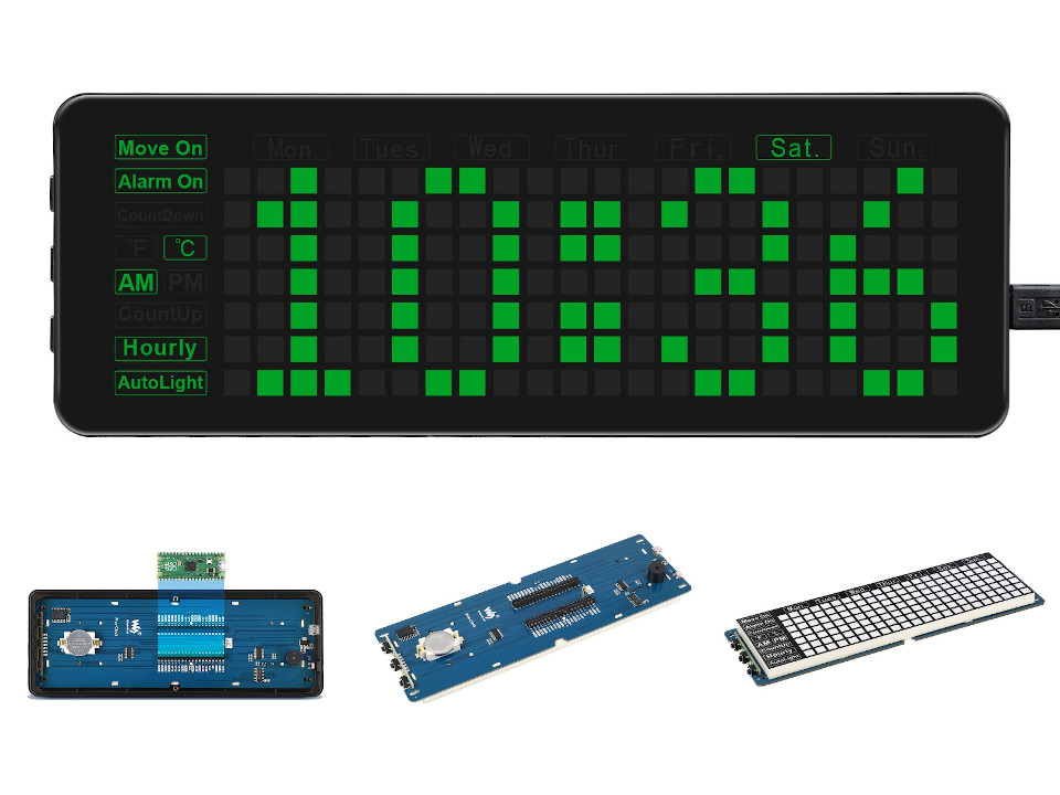
Raspberry Pi Pico Clock Shields
This is a collection of very versatile clocks due to its different feature sets and sizes, the RGB capabilities and additional buttons and sensors. Nearly all displays comes with a special LED controller wired over GPIO or other standard serial buses up to the Raspberry Pi Pico. Additional momentary push buttons or joysticks and a small buzzer are wired up over simple GPIO lines. Some shield provide also a simple temperature sensor or Real-Time-Clock, mostly wired over a dedicated I2C bus.
Supported Shields
Hardware
Features and Resources |
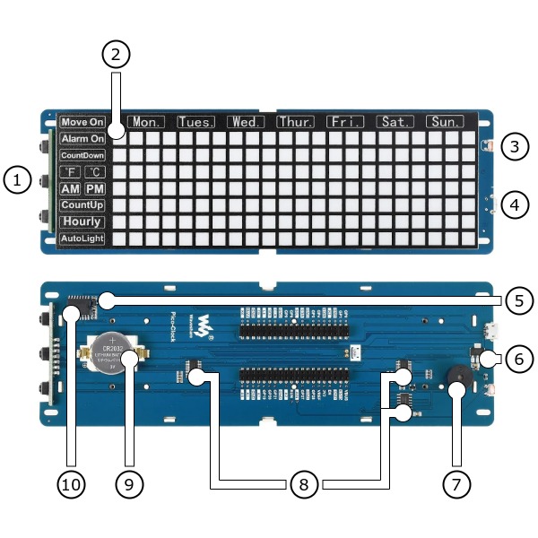
Appliance View |
5V/100㎃ 3.3V/150㎃ USB-B CR2032 SET/FUNCTION UP DOWN PIEZO LED 10 1 1 1 1
Design Data |
|
Positions
|
|---|
|
Data Sheets
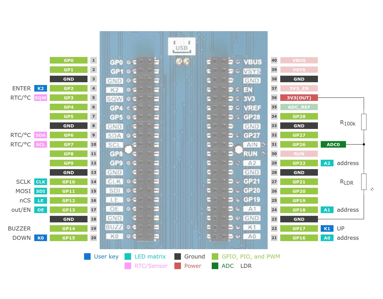
Pinouts
Pin Mapping |
Pinout |
Default Zephyr Peripheral Mapping
Devicetree compatible |
|
LED Matrix |
A 32-bit deep shift register and a 3-bit wide address decoder are connected via pins 14 to 17 as well as 21, 24 and 29. The shift register is structured as serial-in-parallel-out (SIPO) and accepts the bit information of a single LED row in the matrix. Although only 24 bits per line are connected to an LED, 32 bits must always be shifted for each row. This results in an 8-bit zero padding at the end of each LED line. The 8 available rows are realized by an address decoder. This is designed as a 1-of-8 decoder and serves as a line multiplexer (MUX) in the LED matrix.

SIPO-MUX-GP (General Purpose) over SPI
The multi-functional device
SIPO-MUX-GPIO for row 0 over SIPO-MUX-GP
sipo-mux-gpio@0
Access to the two white signaling LED Sign 0 and Sign 1 (between the three buttons on left side) and the double LED tiles Move On, Mon., Tues., Wed., Thur., Fri., Sat. and Sun. by LED alias or the following GPIO line names:
SIPO-MUX-GPIO for row 1 over SIPO-MUX-GP
sipo-mux-gpio@1
Access to the double LED tile Alarm On by LED alias or the following GPIO line names:
SIPO-MUX-GPIO for row 2 over SIPO-MUX-GP
sipo-mux-gpio@2
Access to the double LED tile CountDown by LED alias or the following GPIO line names:
SIPO-MUX-GPIO for row 3 over SIPO-MUX-GP
sipo-mux-gpio@3
Access to the single LED tiles ℉ and ℃ by LED alias or the following GPIO line names:
SIPO-MUX-GPIO for row 4 over SIPO-MUX-GP
sipo-mux-gpio@4
Access to the single LED tiles ㏂ and ㏘ by LED alias or the following GPIO line names:
SIPO-MUX-GPIO for row 5 over SIPO-MUX-GP
sipo-mux-gpio@5
Access to the double LED tile CountUp by LED alias or the following GPIO line names:
SIPO-MUX-GPIO for row 6 over SIPO-MUX-GP
sipo-mux-gpio@6
Access to the double LED tile Hourly by LED alias or the following GPIO line names:
SIPO-MUX-GPIO for row 7 over SIPO-MUX-GP
sipo-mux-gpio@7
Access to the double LED tile AutoLight by LED alias or the following GPIO line names:
SIPO-MUX-DISPLAY over SIPO-MUX-GP
With an x,y-offset of 2,1 the display provides 7 pixel in height (Y) and 22 pixel in width (X).
Devicetree compatible |
Utilization
This shields can be used with any development board, shield, or snippet that
provides a Devicetree node with the raspberrypi,pico-header-r3
property for the compatibility. In particular, the I2C1 bus on pins 9 to 10 and
some GPIO signals on pins 4 to 5, 14 to 22, 24 and 29 of this edge connector
must be free for communication with the buttons, buzzer, LEDs, RTC and sensors
on the shields. The ADC channel 0 on pin 31 must also be free for communication
with the on-shield LDR (photoresistor). The shields also provide the special
Devicetree labels &rpipico_i2c_rtc, &clock_rtc,
&rpipico_pwm_buzzers and &clock_buzzer for this
purpose.
Programming
Set -DSHIELD=geeekpi_pico_bb_plus and use optional the
USB Console Snippet (usb-console) when you invoke west build.
For example:
west build -b rpi_pico/rp2040/bbe -p -S "usb-console" --shield "waveshare_pico_clock_green" -d build/waveshare_pico_clock_green-helloshell bridle/samples/helloshell
west flash -r uf2 -d build/waveshare_pico_clock_green-helloshell
Simple test execution on target
(text in bold is a command input)
uart:~$ hello -h
hello - say hello
uart:~$ hello
Hello from shell.
uart:~$ hwinfo devid
Length: 8
ID: 0x8c998be1de969148

uart:~$ kernel version
Zephyr version 4.4.99

uart:~$ bridle version
Bridle version 4.4.99

uart:~$ bridle version long
Bridle version 4.4.99.0

uart:~$ bridle info
Zephyr: 4.4.99
Bridle: 4.4.99
uart:~$ device list
devices:
- clock-controller@40008000 (READY)
  DT node labels: clocks
- reset-controller@4000c000 (READY)
  DT node labels: reset
- snippet_cdc_acm_console_uart (READY)
  DT node labels: snippet_cdc_acm_console_uart
- uart@40034000 (READY)
  DT node labels: uart0 pico_serial rpipico_serial
- timer@40054000 (READY)
  DT node labels: timer
- gpio-port@0 (READY)
  DT node labels: gpio0 rpipico_gpio_keys clock_gpio_keys
- usbd@50110000 (READY)
  DT node labels: usbd zephyr_udc0
- adc@4004c000 (READY)
  DT node labels: adc
- flash-controller@18000000 (READY)
  DT node labels: ssi
- i2c@40048000 (READY)
  DT node labels: i2c1 pico_i2c1 rpipico_i2c1 rpipico_i2c_rtc clock_i2c_rtc
- i2c@40044000 (READY)
  DT node labels: i2c0 pico_i2c pico_i2c0 rpipico_i2c rpipico_i2c0
- pwm@40050000 (READY)
  DT node labels: pwm rpipico_pwm_buzzers clock_pwm_buzzers
- vreg@40064000 (READY)
  DT node labels: vreg
- rtc@4005c000 (READY)
  DT node labels: rtc
- spi@40040000 (READY)
  DT node labels: spi1 pico_spi1 rpipico_spi1 rpipico_spi_leds clock_spi_leds
- spi@4003c000 (READY)
  DT node labels: spi0 pico_spi pico_spi0 rpipico_spi rpipico_spi0
- ds3231-mfd@68 (READY)
  DT node labels: ds3231_mfd clock_mfd
- sipo-mux-gp@0 (READY)
  DT node labels: sipo_mux_gp clock_sipo_mux
- sipo-mux-gpio@7 (READY)
  DT node labels: sipo_mux_gpio_7 clock_gpio_7
- sipo-mux-gpio@6 (READY)
  DT node labels: sipo_mux_gpio_6 clock_gpio_6
- sipo-mux-gpio@5 (READY)
  DT node labels: sipo_mux_gpio_5 clock_gpio_5
- sipo-mux-gpio@4 (READY)
  DT node labels: sipo_mux_gpio_4 clock_gpio_4
- sipo-mux-gpio@3 (READY)
  DT node labels: sipo_mux_gpio_3 clock_gpio_3
- sipo-mux-gpio@2 (READY)
  DT node labels: sipo_mux_gpio_2 clock_gpio_2
- sipo-mux-gpio@1 (READY)
  DT node labels: sipo_mux_gpio_1 clock_gpio_1
- sipo-mux-gpio@0 (READY)
  DT node labels: sipo_mux_gpio_0 clock_gpio_0
- ds3231-rtc (READY)
  DT node labels: ds3231_rtc clock_rtc
- ds3231-dts (READY)
  DT node labels: ds3231_dts clock_dts
- wpcg-gpio-leds (READY)
  DT node labels: wpcg_gpio_leds
uart:~$ history
[  0] history
[  1] device list
[  2] bridle info
[  3] bridle version long
[  4] bridle version
[  5] kernel version
[  6] hwinfo devid
[  7] hello
[  8] hello -h
Operate with the first user LED SIG0 on the left side at SIPOMUX-GPIO0:SIG0:
uart:~$ led on wpcg-gpio-leds 0
wpcg-gpio-leds: turning on LED 0
uart:~$ led set_brightness wpcg-gpio-leds 0 0
wpcg-gpio-leds: setting LED 0 brightness to 0
uart:~$ led set_brightness wpcg-gpio-leds 0 50
wpcg-gpio-leds: setting LED 0 brightness to 50
uart:~$ led off wpcg-gpio-leds 0
wpcg-gpio-leds: turning off LED 0
Operate with the first user LED SIG0 on the left side at SIPOMUX-GPIO0:SIG0:
uart:~$ gpio get clock_gpio_0 SIG0
0

uart:~$ gpio conf clock_gpio_0 SIG0 oh0

uart:~$ gpio set clock_gpio_0 SIG0 1
uart:~$ gpio set clock_gpio_0 SIG0 0

uart:~$ gpio blink clock_gpio_0 SIG0
Hit any key to exit
Operate with the user input button SET/FUNCTION at GP2:
uart:~$ gpio get clock_gpio_keys SET
0

uart:~$ gpio conf clock_gpio_keys SET iul
uart:~$ gpio get clock_gpio_keys SET
0
uart:~$ gpio get clock_gpio_keys SET
1
uart:~$ gpio get clock_gpio_keys SET
0
Operate with the on-shield high-resistance LDR Rₗ on ADC_CH0:
uart:~$ adc adc@4004c000 resolution 12
uart:~$ adc adc@4004c000 read 0
read: 51
uart:~$ adc adc@4004c000 read 0
read: 883
uart:~$ adc adc@4004c000 read 0
read: 3147
The Waveshare Pico Clock Green has the on-shield RTC connected on I2C1.
uart:~$ i2c scan clock_i2c_rtc
     0  1  2  3  4  5  6  7  8  9  a  b  c  d  e  f
00:             -- -- -- -- -- -- -- -- -- -- -- --
10: -- -- -- -- -- -- -- -- -- -- -- -- -- -- -- --
20: -- -- -- -- -- -- -- -- -- -- -- -- -- -- -- --
30: -- -- -- -- -- -- -- -- -- -- -- -- -- -- -- --
40: -- -- -- -- -- -- -- -- -- -- -- -- -- -- -- --
50: -- -- -- -- -- -- -- -- -- -- -- -- -- -- -- --
60: -- -- -- -- -- -- -- -- 68 -- -- -- -- -- -- --
70: -- -- -- -- -- -- -- --
1 devices found on clock_i2c_rtc
The I2C address 0x68 is a Maxim / Analog Devices DS3231 [27] RTC with
integraterd Temperature Sensor and they current temperature can read
from registers 0x11 (MSB) and 0x12 (LSB). For example, for
26.25℃ the register content must be 0x1a and 0x40:
uart:~$ i2c read_byte clock_i2c_rtc 68 11
Output: 0x1a
uart:~$ i2c read_byte clock_i2c_rtc 68 12
Output: 0x40
For example, for 24.75℃ the register content must be 0x18
and 0xc0:
uart:~$ i2c read_byte clock_i2c_rtc 68 11
Output: 0x18
uart:~$ i2c read_byte clock_i2c_rtc 68 12
Output: 0xc0
uart:~$ rtc get clock_rtc
uart:~$ rtc set clock_rtc 2013-12-11T10:09:08
uart:~$ rtc get clock_rtc
2013-12-11T10:09:16.000
uart:~$ sensor info
device name: ds3231-dts, vendor: Maxim Integrated Products, model: ds3231-sensor, friendly name: Pico Color Green TP Sensor (in RTC)
uart:~$ sensor get clock_dts 13
channel type=13(ambient_temp) index=0 shift=7 num_samples=1 value=958127057056ns (24.750000)
On ARM Cortex-M33
west build -b rpi_pico2/rp2350a/m33/bbe -p -S "usb-console" --shield "waveshare_pico_clock_green" -d build/waveshare_pico_clock_green-helloshell bridle/samples/helloshell
west flash -r uf2 -d build/waveshare_pico_clock_green-helloshell
On Hazard3 RISC-V (RV32IMAC+)
west build -b rpi_pico2/rp2350a/hazard3/bbe -p -S "usb-console" --shield "waveshare_pico_clock_green" -d build/waveshare_pico_clock_green-helloshell bridle/samples/helloshell
west flash -r uf2 -d build/waveshare_pico_clock_green-helloshell
Simple test execution on target
(text in bold is a command input)
uart:~$ hello -h
hello - say hello
uart:~$ hello
Hello from shell.
uart:~$ hwinfo devid
Length: 8
ID: 0x8c998be1de969148

uart:~$ kernel version
Zephyr version 4.4.99

uart:~$ bridle version
Bridle version 4.4.99

uart:~$ bridle version long
Bridle version 4.4.99.0

uart:~$ bridle info
Zephyr: 4.4.99
Bridle: 4.4.99
uart:~$ device list
devices:
- clock-controller@40008000 (READY)
  DT node labels: clocks
- reset-controller@4000c000 (READY)
  DT node labels: reset
- snippet_cdc_acm_console_uart (READY)
  DT node labels: snippet_cdc_acm_console_uart
- uart@40034000 (READY)
  DT node labels: uart0 pico_serial rpipico_serial
- timer@40054000 (READY)
  DT node labels: timer
- gpio-port@0 (READY)
  DT node labels: gpio0 rpipico_gpio_keys clock_gpio_keys
- usbd@50110000 (READY)
  DT node labels: usbd zephyr_udc0
- adc@4004c000 (READY)
  DT node labels: adc
- flash-controller@18000000 (READY)
  DT node labels: ssi
- i2c@40048000 (READY)
  DT node labels: i2c1 pico_i2c1 rpipico_i2c1 rpipico_i2c_rtc clock_i2c_rtc
- i2c@40044000 (READY)
  DT node labels: i2c0 pico_i2c pico_i2c0 rpipico_i2c rpipico_i2c0
- pwm@40050000 (READY)
  DT node labels: pwm rpipico_pwm_buzzers clock_pwm_buzzers
- vreg@40064000 (READY)
  DT node labels: vreg
- rtc@4005c000 (READY)
  DT node labels: rtc
- spi@40040000 (READY)
  DT node labels: spi1 pico_spi1 rpipico_spi1 rpipico_spi_leds clock_spi_leds
- spi@4003c000 (READY)
  DT node labels: spi0 pico_spi pico_spi0 rpipico_spi rpipico_spi0
- ds3231-mfd@68 (READY)
  DT node labels: ds3231_mfd clock_mfd
- sipo-mux-gp@0 (READY)
  DT node labels: sipo_mux_gp clock_sipo_mux
- sipo-mux-gpio@7 (READY)
  DT node labels: sipo_mux_gpio_7 clock_gpio_7
- sipo-mux-gpio@6 (READY)
  DT node labels: sipo_mux_gpio_6 clock_gpio_6
- sipo-mux-gpio@5 (READY)
  DT node labels: sipo_mux_gpio_5 clock_gpio_5
- sipo-mux-gpio@4 (READY)
  DT node labels: sipo_mux_gpio_4 clock_gpio_4
- sipo-mux-gpio@3 (READY)
  DT node labels: sipo_mux_gpio_3 clock_gpio_3
- sipo-mux-gpio@2 (READY)
  DT node labels: sipo_mux_gpio_2 clock_gpio_2
- sipo-mux-gpio@1 (READY)
  DT node labels: sipo_mux_gpio_1 clock_gpio_1
- sipo-mux-gpio@0 (READY)
  DT node labels: sipo_mux_gpio_0 clock_gpio_0
- ds3231-rtc (READY)
  DT node labels: ds3231_rtc clock_rtc
- ds3231-dts (READY)
  DT node labels: ds3231_dts clock_dts
- wpcg-gpio-leds (READY)
  DT node labels: wpcg_gpio_leds
uart:~$ history
[  0] history
[  1] device list
[  2] bridle info
[  3] bridle version long
[  4] bridle version
[  5] kernel version
[  6] hwinfo devid
[  7] hello
[  8] hello -h
Operate with the first user LED SIG0 on the left side at SIPOMUX-GPIO0:SIG0:
uart:~$ led on wpcg-gpio-leds 0
wpcg-gpio-leds: turning on LED 0
uart:~$ led set_brightness wpcg-gpio-leds 0 0
wpcg-gpio-leds: setting LED 0 brightness to 0
uart:~$ led set_brightness wpcg-gpio-leds 0 50
wpcg-gpio-leds: setting LED 0 brightness to 50
uart:~$ led off wpcg-gpio-leds 0
wpcg-gpio-leds: turning off LED 0
Operate with the first user LED SIG0 on the left side at SIPOMUX-GPIO0:SIG0:
uart:~$ gpio get clock_gpio_0 SIG0
0

uart:~$ gpio conf clock_gpio_0 SIG0 oh0

uart:~$ gpio set clock_gpio_0 SIG0 1
uart:~$ gpio set clock_gpio_0 SIG0 0

uart:~$ gpio blink clock_gpio_0 SIG0
Hit any key to exit
Operate with the user input button SET/FUNCTION at GP2:
uart:~$ gpio get clock_gpio_keys SET
0

uart:~$ gpio conf clock_gpio_keys SET iul
uart:~$ gpio get clock_gpio_keys SET
0
uart:~$ gpio get clock_gpio_keys SET
1
uart:~$ gpio get clock_gpio_keys SET
0
Operate with the on-shield high-resistance LDR Rₗ on ADC_CH0:
uart:~$ adc adc@4004c000 resolution 12
uart:~$ adc adc@4004c000 read 0
read: 51
uart:~$ adc adc@4004c000 read 0
read: 883
uart:~$ adc adc@4004c000 read 0
read: 3147
The Waveshare Pico Clock Green has the on-shield RTC connected on I2C1.
uart:~$ i2c scan clock_i2c_rtc
     0  1  2  3  4  5  6  7  8  9  a  b  c  d  e  f
00:             -- -- -- -- -- -- -- -- -- -- -- --
10: -- -- -- -- -- -- -- -- -- -- -- -- -- -- -- --
20: -- -- -- -- -- -- -- -- -- -- -- -- -- -- -- --
30: -- -- -- -- -- -- -- -- -- -- -- -- -- -- -- --
40: -- -- -- -- -- -- -- -- -- -- -- -- -- -- -- --
50: -- -- -- -- -- -- -- -- -- -- -- -- -- -- -- --
60: -- -- -- -- -- -- -- -- 68 -- -- -- -- -- -- --
70: -- -- -- -- -- -- -- --
1 devices found on clock_i2c_rtc
The I2C address 0x68 is a Maxim / Analog Devices DS3231 [27] RTC with
integraterd Temperature Sensor and they current temperature can read
from registers 0x11 (MSB) and 0x12 (LSB). For example, for
26.25℃ the register content must be 0x1a and 0x40:
uart:~$ i2c read_byte clock_i2c_rtc 68 11
Output: 0x1a
uart:~$ i2c read_byte clock_i2c_rtc 68 12
Output: 0x40
For example, for 24.75℃ the register content must be 0x18
and 0xc0:
uart:~$ i2c read_byte clock_i2c_rtc 68 11
Output: 0x18
uart:~$ i2c read_byte clock_i2c_rtc 68 12
Output: 0xc0
uart:~$ rtc get clock_rtc
uart:~$ rtc set clock_rtc 2013-12-11T10:09:08
uart:~$ rtc get clock_rtc
2013-12-11T10:09:16.000
uart:~$ sensor info
device name: ds3231-dts, vendor: Maxim Integrated Products, model: ds3231-sensor, friendly name: Pico Color Green TP Sensor (in RTC)
uart:~$ sensor get clock_dts 13
channel type=13(ambient_temp) index=0 shift=7 num_samples=1 value=958127057056ns (24.750000)
On ARM Cortex-M33
west build -b rpi_pico2/rp2350a/m33/w/bbe -p -S "usb-console wifi-ip" --shield "waveshare_pico_clock_green" -d build/waveshare_pico_clock_green-helloshell bridle/samples/helloshell
west flash -r uf2 -d build/waveshare_pico_clock_green-helloshell
Simple test execution on target
(text in bold is a command input)
uart:~$ hello -h
hello - say hello
uart:~$ hello
Hello from shell.
uart:~$ hwinfo devid
Length: 8
ID: 0x8c998be1de969148

uart:~$ kernel version
Zephyr version 4.4.99

uart:~$ bridle version
Bridle version 4.4.99

uart:~$ bridle version long
Bridle version 4.4.99.0

uart:~$ bridle info
Zephyr: 4.4.99
Bridle: 4.4.99
uart:~$ device list
devices:
- clock-controller@40008000 (READY)
  DT node labels: clocks
- reset-controller@4000c000 (READY)
  DT node labels: reset
- snippet_cdc_acm_console_uart (READY)
  DT node labels: snippet_cdc_acm_console_uart
- uart@40034000 (READY)
  DT node labels: uart0 pico_serial rpipico_serial
- timer@40054000 (READY)
  DT node labels: timer
- gpio-port@0 (READY)
  DT node labels: gpio0 rpipico_gpio_keys clock_gpio_keys
- usbd@50110000 (READY)
  DT node labels: usbd zephyr_udc0
- adc@4004c000 (READY)
  DT node labels: adc
- flash-controller@18000000 (READY)
  DT node labels: ssi
- i2c@40048000 (READY)
  DT node labels: i2c1 pico_i2c1 rpipico_i2c1 rpipico_i2c_rtc clock_i2c_rtc
- i2c@40044000 (READY)
  DT node labels: i2c0 pico_i2c pico_i2c0 rpipico_i2c rpipico_i2c0
- pwm@40050000 (READY)
  DT node labels: pwm rpipico_pwm_buzzers clock_pwm_buzzers
- vreg@40064000 (READY)
  DT node labels: vreg
- rtc@4005c000 (READY)
  DT node labels: rtc
- spi@40040000 (READY)
  DT node labels: spi1 pico_spi1 rpipico_spi1 rpipico_spi_leds clock_spi_leds
- spi@4003c000 (READY)
  DT node labels: spi0 pico_spi pico_spi0 rpipico_spi rpipico_spi0
- ds3231-mfd@68 (READY)
  DT node labels: ds3231_mfd clock_mfd
- sipo-mux-gp@0 (READY)
  DT node labels: sipo_mux_gp clock_sipo_mux
- sipo-mux-gpio@7 (READY)
  DT node labels: sipo_mux_gpio_7 clock_gpio_7
- sipo-mux-gpio@6 (READY)
  DT node labels: sipo_mux_gpio_6 clock_gpio_6
- sipo-mux-gpio@5 (READY)
  DT node labels: sipo_mux_gpio_5 clock_gpio_5
- sipo-mux-gpio@4 (READY)
  DT node labels: sipo_mux_gpio_4 clock_gpio_4
- sipo-mux-gpio@3 (READY)
  DT node labels: sipo_mux_gpio_3 clock_gpio_3
- sipo-mux-gpio@2 (READY)
  DT node labels: sipo_mux_gpio_2 clock_gpio_2
- sipo-mux-gpio@1 (READY)
  DT node labels: sipo_mux_gpio_1 clock_gpio_1
- sipo-mux-gpio@0 (READY)
  DT node labels: sipo_mux_gpio_0 clock_gpio_0
- ds3231-rtc (READY)
  DT node labels: ds3231_rtc clock_rtc
- ds3231-dts (READY)
  DT node labels: ds3231_dts clock_dts
- wpcg-gpio-leds (READY)
  DT node labels: wpcg_gpio_leds
uart:~$ history
[  0] history
[  1] device list
[  2] bridle info
[  3] bridle version long
[  4] bridle version
[  5] kernel version
[  6] hwinfo devid
[  7] hello
[  8] hello -h
Operate with the first user LED SIG0 on the left side at SIPOMUX-GPIO0:SIG0:
uart:~$ led on wpcg-gpio-leds 0
wpcg-gpio-leds: turning on LED 0
uart:~$ led set_brightness wpcg-gpio-leds 0 0
wpcg-gpio-leds: setting LED 0 brightness to 0
uart:~$ led set_brightness wpcg-gpio-leds 0 50
wpcg-gpio-leds: setting LED 0 brightness to 50
uart:~$ led off wpcg-gpio-leds 0
wpcg-gpio-leds: turning off LED 0
Operate with the first user LED SIG0 on the left side at SIPOMUX-GPIO0:SIG0:
uart:~$ gpio get clock_gpio_0 SIG0
0

uart:~$ gpio conf clock_gpio_0 SIG0 oh0

uart:~$ gpio set clock_gpio_0 SIG0 1
uart:~$ gpio set clock_gpio_0 SIG0 0

uart:~$ gpio blink clock_gpio_0 SIG0
Hit any key to exit
Operate with the user input button SET/FUNCTION at GP2:
uart:~$ gpio get clock_gpio_keys SET
0

uart:~$ gpio conf clock_gpio_keys SET iul
uart:~$ gpio get clock_gpio_keys SET
0
uart:~$ gpio get clock_gpio_keys SET
1
uart:~$ gpio get clock_gpio_keys SET
0
Operate with the on-shield high-resistance LDR Rₗ on ADC_CH0:
uart:~$ adc adc@4004c000 resolution 12
uart:~$ adc adc@4004c000 read 0
read: 51
uart:~$ adc adc@4004c000 read 0
read: 883
uart:~$ adc adc@4004c000 read 0
read: 3147
The Waveshare Pico Clock Green has the on-shield RTC connected on I2C1.
uart:~$ i2c scan clock_i2c_rtc
     0  1  2  3  4  5  6  7  8  9  a  b  c  d  e  f
00:             -- -- -- -- -- -- -- -- -- -- -- --
10: -- -- -- -- -- -- -- -- -- -- -- -- -- -- -- --
20: -- -- -- -- -- -- -- -- -- -- -- -- -- -- -- --
30: -- -- -- -- -- -- -- -- -- -- -- -- -- -- -- --
40: -- -- -- -- -- -- -- -- -- -- -- -- -- -- -- --
50: -- -- -- -- -- -- -- -- -- -- -- -- -- -- -- --
60: -- -- -- -- -- -- -- -- 68 -- -- -- -- -- -- --
70: -- -- -- -- -- -- -- --
1 devices found on clock_i2c_rtc
The I2C address 0x68 is a Maxim / Analog Devices DS3231 [27] RTC with
integraterd Temperature Sensor and they current temperature can read
from registers 0x11 (MSB) and 0x12 (LSB). For example, for
26.25℃ the register content must be 0x1a and 0x40:
uart:~$ i2c read_byte clock_i2c_rtc 68 11
Output: 0x1a
uart:~$ i2c read_byte clock_i2c_rtc 68 12
Output: 0x40
For example, for 24.75℃ the register content must be 0x18
and 0xc0:
uart:~$ i2c read_byte clock_i2c_rtc 68 11
Output: 0x18
uart:~$ i2c read_byte clock_i2c_rtc 68 12
Output: 0xc0
uart:~$ rtc get clock_rtc
uart:~$ rtc set clock_rtc 2013-12-11T10:09:08
uart:~$ rtc get clock_rtc
2013-12-11T10:09:16.000
uart:~$ sensor info
device name: ds3231-dts, vendor: Maxim Integrated Products, model: ds3231-sensor, friendly name: Pico Color Green TP Sensor (in RTC)
uart:~$ sensor get clock_dts 13
channel type=13(ambient_temp) index=0 shift=7 num_samples=1 value=958127057056ns (24.750000)
west build -b rpi_pico/rp2040/w/bbe -p -S "usb-console wifi-ip" --shield "waveshare_pico_clock_green" -d build/waveshare_pico_clock_green-helloshell bridle/samples/helloshell
west flash -r uf2 -d build/waveshare_pico_clock_green-helloshell
Simple test execution on target
(text in bold is a command input)
uart:~$ hello -h
hello - say hello
uart:~$ hello
Hello from shell.
uart:~$ hwinfo devid
Length: 8
ID: 0x8c998be1de969148

uart:~$ kernel version
Zephyr version 4.4.99

uart:~$ bridle version
Bridle version 4.4.99

uart:~$ bridle version long
Bridle version 4.4.99.0

uart:~$ bridle info
Zephyr: 4.4.99
Bridle: 4.4.99
uart:~$ device list
devices:
- clock-controller@40008000 (READY)
  DT node labels: clocks
- reset-controller@4000c000 (READY)
  DT node labels: reset
- snippet_cdc_acm_console_uart (READY)
  DT node labels: snippet_cdc_acm_console_uart
- uart@40034000 (READY)
  DT node labels: uart0 pico_serial rpipico_serial
- timer@40054000 (READY)
  DT node labels: timer
- gpio-port@0 (READY)
  DT node labels: gpio0 rpipico_gpio_keys clock_gpio_keys
- usbd@50110000 (READY)
  DT node labels: usbd zephyr_udc0
- adc@4004c000 (READY)
  DT node labels: adc
- flash-controller@18000000 (READY)
  DT node labels: ssi
- i2c@40048000 (READY)
  DT node labels: i2c1 pico_i2c1 rpipico_i2c1 rpipico_i2c_rtc clock_i2c_rtc
- i2c@40044000 (READY)
  DT node labels: i2c0 pico_i2c pico_i2c0 rpipico_i2c rpipico_i2c0
- pwm@40050000 (READY)
  DT node labels: pwm rpipico_pwm_buzzers clock_pwm_buzzers
- vreg@40064000 (READY)
  DT node labels: vreg
- rtc@4005c000 (READY)
  DT node labels: rtc
- spi@40040000 (READY)
  DT node labels: spi1 pico_spi1 rpipico_spi1 rpipico_spi_leds clock_spi_leds
- spi@4003c000 (READY)
  DT node labels: spi0 pico_spi pico_spi0 rpipico_spi rpipico_spi0
- ds3231-mfd@68 (READY)
  DT node labels: ds3231_mfd clock_mfd
- sipo-mux-gp@0 (READY)
  DT node labels: sipo_mux_gp clock_sipo_mux
- sipo-mux-gpio@7 (READY)
  DT node labels: sipo_mux_gpio_7 clock_gpio_7
- sipo-mux-gpio@6 (READY)
  DT node labels: sipo_mux_gpio_6 clock_gpio_6
- sipo-mux-gpio@5 (READY)
  DT node labels: sipo_mux_gpio_5 clock_gpio_5
- sipo-mux-gpio@4 (READY)
  DT node labels: sipo_mux_gpio_4 clock_gpio_4
- sipo-mux-gpio@3 (READY)
  DT node labels: sipo_mux_gpio_3 clock_gpio_3
- sipo-mux-gpio@2 (READY)
  DT node labels: sipo_mux_gpio_2 clock_gpio_2
- sipo-mux-gpio@1 (READY)
  DT node labels: sipo_mux_gpio_1 clock_gpio_1
- sipo-mux-gpio@0 (READY)
  DT node labels: sipo_mux_gpio_0 clock_gpio_0
- ds3231-rtc (READY)
  DT node labels: ds3231_rtc clock_rtc
- ds3231-dts (READY)
  DT node labels: ds3231_dts clock_dts
- wpcg-gpio-leds (READY)
  DT node labels: wpcg_gpio_leds
uart:~$ history
[  0] history
[  1] device list
[  2] bridle info
[  3] bridle version long
[  4] bridle version
[  5] kernel version
[  6] hwinfo devid
[  7] hello
[  8] hello -h
Operate with the first user LED SIG0 on the left side at SIPOMUX-GPIO0:SIG0:
uart:~$ led on wpcg-gpio-leds 0
wpcg-gpio-leds: turning on LED 0
uart:~$ led set_brightness wpcg-gpio-leds 0 0
wpcg-gpio-leds: setting LED 0 brightness to 0
uart:~$ led set_brightness wpcg-gpio-leds 0 50
wpcg-gpio-leds: setting LED 0 brightness to 50
uart:~$ led off wpcg-gpio-leds 0
wpcg-gpio-leds: turning off LED 0
Operate with the first user LED SIG0 on the left side at SIPOMUX-GPIO0:SIG0:
uart:~$ gpio get clock_gpio_0 SIG0
0

uart:~$ gpio conf clock_gpio_0 SIG0 oh0

uart:~$ gpio set clock_gpio_0 SIG0 1
uart:~$ gpio set clock_gpio_0 SIG0 0

uart:~$ gpio blink clock_gpio_0 SIG0
Hit any key to exit
Operate with the user input button SET/FUNCTION at GP2:
uart:~$ gpio get clock_gpio_keys SET
0

uart:~$ gpio conf clock_gpio_keys SET iul
uart:~$ gpio get clock_gpio_keys SET
0
uart:~$ gpio get clock_gpio_keys SET
1
uart:~$ gpio get clock_gpio_keys SET
0
Operate with the on-shield high-resistance LDR Rₗ on ADC_CH0:
uart:~$ adc adc@4004c000 resolution 12
uart:~$ adc adc@4004c000 read 0
read: 51
uart:~$ adc adc@4004c000 read 0
read: 883
uart:~$ adc adc@4004c000 read 0
read: 3147
The Waveshare Pico Clock Green has the on-shield RTC connected on I2C1.
uart:~$ i2c scan clock_i2c_rtc
     0  1  2  3  4  5  6  7  8  9  a  b  c  d  e  f
00:             -- -- -- -- -- -- -- -- -- -- -- --
10: -- -- -- -- -- -- -- -- -- -- -- -- -- -- -- --
20: -- -- -- -- -- -- -- -- -- -- -- -- -- -- -- --
30: -- -- -- -- -- -- -- -- -- -- -- -- -- -- -- --
40: -- -- -- -- -- -- -- -- -- -- -- -- -- -- -- --
50: -- -- -- -- -- -- -- -- -- -- -- -- -- -- -- --
60: -- -- -- -- -- -- -- -- 68 -- -- -- -- -- -- --
70: -- -- -- -- -- -- -- --
1 devices found on clock_i2c_rtc
The I2C address 0x68 is a Maxim / Analog Devices DS3231 [27] RTC with
integraterd Temperature Sensor and they current temperature can read
from registers 0x11 (MSB) and 0x12 (LSB). For example, for
26.25℃ the register content must be 0x1a and 0x40:
uart:~$ i2c read_byte clock_i2c_rtc 68 11
Output: 0x1a
uart:~$ i2c read_byte clock_i2c_rtc 68 12
Output: 0x40
For example, for 24.75℃ the register content must be 0x18
and 0xc0:
uart:~$ i2c read_byte clock_i2c_rtc 68 11
Output: 0x18
uart:~$ i2c read_byte clock_i2c_rtc 68 12
Output: 0xc0
uart:~$ rtc get clock_rtc
uart:~$ rtc set clock_rtc 2013-12-11T10:09:08
uart:~$ rtc get clock_rtc
2013-12-11T10:09:16.000
uart:~$ sensor info
device name: ds3231-dts, vendor: Maxim Integrated Products, model: ds3231-sensor, friendly name: Pico Color Green TP Sensor (in RTC)
uart:~$ sensor get clock_dts 13
channel type=13(ambient_temp) index=0 shift=7 num_samples=1 value=958127057056ns (24.750000)
on standard 4㎆ revision
west build -b waveshare_rp2040_plus -p -S "usb-console" --shield "waveshare_pico_clock_green" -d build/waveshare_pico_clock_green-helloshell bridle/samples/helloshell
west flash -r uf2 -d build/waveshare_pico_clock_green-helloshell
on extended 16㎆ revision
west build -b waveshare_rp2040_plus@16mb -p -S "usb-console" --shield "waveshare_pico_clock_green" -d build/waveshare_pico_clock_green-helloshell bridle/samples/helloshell
west flash -r uf2 -d build/waveshare_pico_clock_green-helloshell
Simple test execution on target
(text in bold is a command input)
uart:~$ hello -h
hello - say hello
uart:~$ hello
Hello from shell.
uart:~$ hwinfo devid
Length: 8
ID: 0x8c998be1de969148

uart:~$ kernel version
Zephyr version 4.4.99

uart:~$ bridle version
Bridle version 4.4.99

uart:~$ bridle version long
Bridle version 4.4.99.0

uart:~$ bridle info
Zephyr: 4.4.99
Bridle: 4.4.99
uart:~$ device list
devices:
- clock-controller@40008000 (READY)
  DT node labels: clocks
- reset-controller@4000c000 (READY)
  DT node labels: reset
- snippet_cdc_acm_console_uart (READY)
  DT node labels: snippet_cdc_acm_console_uart
- uart@40034000 (READY)
  DT node labels: uart0 pico_serial rpipico_serial
- timer@40054000 (READY)
  DT node labels: timer
- gpio-port@0 (READY)
  DT node labels: gpio0 rpipico_gpio_keys clock_gpio_keys
- usbd@50110000 (READY)
  DT node labels: usbd zephyr_udc0
- adc@4004c000 (READY)
  DT node labels: adc
- flash-controller@18000000 (READY)
  DT node labels: ssi
- i2c@40048000 (READY)
  DT node labels: i2c1 pico_i2c1 rpipico_i2c1 rpipico_i2c_rtc clock_i2c_rtc
- i2c@40044000 (READY)
  DT node labels: i2c0 pico_i2c pico_i2c0 rpipico_i2c rpipico_i2c0
- pwm@40050000 (READY)
  DT node labels: pwm rpipico_pwm_buzzers clock_pwm_buzzers
- vreg@40064000 (READY)
  DT node labels: vreg
- rtc@4005c000 (READY)
  DT node labels: rtc
- spi@40040000 (READY)
  DT node labels: spi1 pico_spi1 rpipico_spi1 rpipico_spi_leds clock_spi_leds
- spi@4003c000 (READY)
  DT node labels: spi0 pico_spi pico_spi0 rpipico_spi rpipico_spi0
- ds3231-mfd@68 (READY)
  DT node labels: ds3231_mfd clock_mfd
- sipo-mux-gp@0 (READY)
  DT node labels: sipo_mux_gp clock_sipo_mux
- sipo-mux-gpio@7 (READY)
  DT node labels: sipo_mux_gpio_7 clock_gpio_7
- sipo-mux-gpio@6 (READY)
  DT node labels: sipo_mux_gpio_6 clock_gpio_6
- sipo-mux-gpio@5 (READY)
  DT node labels: sipo_mux_gpio_5 clock_gpio_5
- sipo-mux-gpio@4 (READY)
  DT node labels: sipo_mux_gpio_4 clock_gpio_4
- sipo-mux-gpio@3 (READY)
  DT node labels: sipo_mux_gpio_3 clock_gpio_3
- sipo-mux-gpio@2 (READY)
  DT node labels: sipo_mux_gpio_2 clock_gpio_2
- sipo-mux-gpio@1 (READY)
  DT node labels: sipo_mux_gpio_1 clock_gpio_1
- sipo-mux-gpio@0 (READY)
  DT node labels: sipo_mux_gpio_0 clock_gpio_0
- ds3231-rtc (READY)
  DT node labels: ds3231_rtc clock_rtc
- ds3231-dts (READY)
  DT node labels: ds3231_dts clock_dts
- wpcg-gpio-leds (READY)
  DT node labels: wpcg_gpio_leds
uart:~$ history
[  0] history
[  1] device list
[  2] bridle info
[  3] bridle version long
[  4] bridle version
[  5] kernel version
[  6] hwinfo devid
[  7] hello
[  8] hello -h
Operate with the first user LED SIG0 on the left side at SIPOMUX-GPIO0:SIG0:
uart:~$ led on wpcg-gpio-leds 0
wpcg-gpio-leds: turning on LED 0
uart:~$ led set_brightness wpcg-gpio-leds 0 0
wpcg-gpio-leds: setting LED 0 brightness to 0
uart:~$ led set_brightness wpcg-gpio-leds 0 50
wpcg-gpio-leds: setting LED 0 brightness to 50
uart:~$ led off wpcg-gpio-leds 0
wpcg-gpio-leds: turning off LED 0
Operate with the first user LED SIG0 on the left side at SIPOMUX-GPIO0:SIG0:
uart:~$ gpio get clock_gpio_0 SIG0
0

uart:~$ gpio conf clock_gpio_0 SIG0 oh0

uart:~$ gpio set clock_gpio_0 SIG0 1
uart:~$ gpio set clock_gpio_0 SIG0 0

uart:~$ gpio blink clock_gpio_0 SIG0
Hit any key to exit
Operate with the user input button SET/FUNCTION at GP2:
uart:~$ gpio get clock_gpio_keys SET
0

uart:~$ gpio conf clock_gpio_keys SET iul
uart:~$ gpio get clock_gpio_keys SET
0
uart:~$ gpio get clock_gpio_keys SET
1
uart:~$ gpio get clock_gpio_keys SET
0
Operate with the on-shield high-resistance LDR Rₗ on ADC_CH0:
uart:~$ adc adc@4004c000 resolution 12
uart:~$ adc adc@4004c000 read 0
read: 51
uart:~$ adc adc@4004c000 read 0
read: 883
uart:~$ adc adc@4004c000 read 0
read: 3147
The Waveshare Pico Clock Green has the on-shield RTC connected on I2C1.
uart:~$ i2c scan clock_i2c_rtc
     0  1  2  3  4  5  6  7  8  9  a  b  c  d  e  f
00:             -- -- -- -- -- -- -- -- -- -- -- --
10: -- -- -- -- -- -- -- -- -- -- -- -- -- -- -- --
20: -- -- -- -- -- -- -- -- -- -- -- -- -- -- -- --
30: -- -- -- -- -- -- -- -- -- -- -- -- -- -- -- --
40: -- -- -- -- -- -- -- -- -- -- -- -- -- -- -- --
50: -- -- -- -- -- -- -- -- -- -- -- -- -- -- -- --
60: -- -- -- -- -- -- -- -- 68 -- -- -- -- -- -- --
70: -- -- -- -- -- -- -- --
1 devices found on clock_i2c_rtc
The I2C address 0x68 is a Maxim / Analog Devices DS3231 [27] RTC with
integraterd Temperature Sensor and they current temperature can read
from registers 0x11 (MSB) and 0x12 (LSB). For example, for
26.25℃ the register content must be 0x1a and 0x40:
uart:~$ i2c read_byte clock_i2c_rtc 68 11
Output: 0x1a
uart:~$ i2c read_byte clock_i2c_rtc 68 12
Output: 0x40
For example, for 24.75℃ the register content must be 0x18
and 0xc0:
uart:~$ i2c read_byte clock_i2c_rtc 68 11
Output: 0x18
uart:~$ i2c read_byte clock_i2c_rtc 68 12
Output: 0xc0
uart:~$ rtc get clock_rtc
uart:~$ rtc set clock_rtc 2013-12-11T10:09:08
uart:~$ rtc get clock_rtc
2013-12-11T10:09:16.000
uart:~$ sensor info
device name: ds3231-dts, vendor: Maxim Integrated Products, model: ds3231-sensor, friendly name: Pico Color Green TP Sensor (in RTC)
uart:~$ sensor get clock_dts 13
channel type=13(ambient_temp) index=0 shift=7 num_samples=1 value=958127057056ns (24.750000)
More Samples
Input dump
Prints all input events as defined by the shields Devicetree. See also Zephyr sample: Input dump.
Print the input events related to the five on-shield user input keys and two user keys using the Input subsystem API. That are:
zephyr,code = <INPUT_KEY_ENTER>;zephyr,code = <INPUT_KEY_UP>;zephyr,code = <INPUT_KEY_DOWN>;west build -b rpi_pico/rp2040/bbe -p -S "usb-console" --shield "waveshare_pico_clock_green" -d build/waveshare_pico_clock_green-input_dump zephyr/samples/subsys/input/input_dump
west flash -r uf2 -d build/waveshare_pico_clock_green-input_dump
On ARM Cortex-M33
west build -b rpi_pico2/rp2350a/m33/bbe -p -S "usb-console" --shield "waveshare_pico_clock_green" -d build/waveshare_pico_clock_green-input_dump zephyr/samples/subsys/input/input_dump
west flash -r uf2 -d build/waveshare_pico_clock_green-input_dump
On Hazard3 RISC-V (RV32IMAC+)
west build -b rpi_pico2/rp2350a/hazard3/bbe -p -S "usb-console" --shield "waveshare_pico_clock_green" -d build/waveshare_pico_clock_green-input_dump zephyr/samples/subsys/input/input_dump
west flash -r uf2 -d build/waveshare_pico_clock_green-input_dump
On ARM Cortex-M33
west build -b rpi_pico2/rp2350a/m33/w/bbe -p -S "usb-console" --shield "waveshare_pico_clock_green" -d build/waveshare_pico_clock_green-input_dump zephyr/samples/subsys/input/input_dump
west flash -r uf2 -d build/waveshare_pico_clock_green-input_dump
west build -b rpi_pico/rp2040/w/bbe -p -S "usb-console" --shield "waveshare_pico_clock_green" -d build/waveshare_pico_clock_green-input_dump zephyr/samples/subsys/input/input_dump
west flash -r uf2 -d build/waveshare_pico_clock_green-input_dump
on standard 4㎆ revision
west build -b waveshare_rp2040_plus -p -S "usb-console" --shield "waveshare_pico_clock_green" -d build/waveshare_pico_clock_green-input_dump zephyr/samples/subsys/input/input_dump
west flash -r uf2 -d build/waveshare_pico_clock_green-input_dump
on extended 16㎆ revision
west build -b waveshare_rp2040_plus@16mb -p -S "usb-console" --shield "waveshare_pico_clock_green" -d build/waveshare_pico_clock_green-input_dump zephyr/samples/subsys/input/input_dump
west flash -r uf2 -d build/waveshare_pico_clock_green-input_dump
Simple logging output on target
Analog-to-Digital Converter (ADC)
Read analog inputs from ADC channels as defined by the shield’s Devicetree. See also Zephyr sample: Analog-to-Digital Converter (ADC) with devicetree.
Read and print the analog input value from the one on-shield high-resistance LDR using the ADC driver API. That are:
zephyr,user { io-channels = <&adc 0>; };west build -b rpi_pico/rp2040/bbe -p -S "usb-console" --shield "waveshare_pico_clock_green" -d build/waveshare_pico_clock_green-drivers_adc zephyr/samples/drivers/adc/adc_dt
west flash -r uf2 -d build/waveshare_pico_clock_green-drivers_adc
On ARM Cortex-M33
west build -b rpi_pico2/rp2350a/m33/bbe -p -S "usb-console" --shield "waveshare_pico_clock_green" -d build/waveshare_pico_clock_green-drivers_adc zephyr/samples/drivers/adc/adc_dt
west flash -r uf2 -d build/waveshare_pico_clock_green-drivers_adc
On Hazard3 RISC-V (RV32IMAC+)
west build -b rpi_pico2/rp2350a/hazard3/bbe -p -S "usb-console" --shield "waveshare_pico_clock_green" -d build/waveshare_pico_clock_green-drivers_adc zephyr/samples/drivers/adc/adc_dt
west flash -r uf2 -d build/waveshare_pico_clock_green-drivers_adc
On ARM Cortex-M33
west build -b rpi_pico2/rp2350a/m33/w/bbe -p -S "usb-console" --shield "waveshare_pico_clock_green" -d build/waveshare_pico_clock_green-drivers_adc zephyr/samples/drivers/adc/adc_dt
west flash -r uf2 -d build/waveshare_pico_clock_green-drivers_adc
west build -b rpi_pico/rp2040/w/bbe -p -S "usb-console" --shield "waveshare_pico_clock_green" -d build/waveshare_pico_clock_green-drivers_adc zephyr/samples/drivers/adc/adc_dt
west flash -r uf2 -d build/waveshare_pico_clock_green-drivers_adc
on standard 4㎆ revision
west build -b waveshare_rp2040_plus -p -S "usb-console" --shield "waveshare_pico_clock_green" -d build/waveshare_pico_clock_green-drivers_adc zephyr/samples/drivers/adc/adc_dt
west flash -r uf2 -d build/waveshare_pico_clock_green-drivers_adc
on extended 16㎆ revision
west build -b waveshare_rp2040_plus@16mb -p -S "usb-console" --shield "waveshare_pico_clock_green" -d build/waveshare_pico_clock_green-drivers_adc zephyr/samples/drivers/adc/adc_dt
west flash -r uf2 -d build/waveshare_pico_clock_green-drivers_adc
Simple test execution on target
Sounds from the speaker
The sample is prepared for the on-board PIEZO connected to the PWM channel at GP14 / PWM14 (PWM7CHA).
The PWM period is 880 ㎐, twice the concert pitch frequency of 440 ㎐.
west build -b rpi_pico/rp2040/bbe -p -S "usb-console" --shield "waveshare_pico_clock_green" -d build/waveshare_pico_clock_green-buzzer bridle/samples/buzzer
west flash -r uf2 -d build/waveshare_pico_clock_green-buzzer
On ARM Cortex-M33
west build -b rpi_pico2/rp2350a/m33/bbe -p -S "usb-console" --shield "waveshare_pico_clock_green" -d build/waveshare_pico_clock_green-buzzer bridle/samples/buzzer
west flash -r uf2 -d build/waveshare_pico_clock_green-buzzer
On Hazard3 RISC-V (RV32IMAC+)
west build -b rpi_pico2/rp2350a/hazard3/bbe -p -S "usb-console" --shield "waveshare_pico_clock_green" -d build/waveshare_pico_clock_green-buzzer bridle/samples/buzzer
west flash -r uf2 -d build/waveshare_pico_clock_green-buzzer
On ARM Cortex-M33
west build -b rpi_pico2/rp2350a/m33/w/bbe -p -S "usb-console" --shield "waveshare_pico_clock_green" -d build/waveshare_pico_clock_green-buzzer bridle/samples/buzzer
west flash -r uf2 -d build/waveshare_pico_clock_green-buzzer
west build -b rpi_pico/rp2040/w/bbe -p -S "usb-console" --shield "waveshare_pico_clock_green" -d build/waveshare_pico_clock_green-buzzer bridle/samples/buzzer
west flash -r uf2 -d build/waveshare_pico_clock_green-buzzer
on standard 4㎆ revision
west build -b waveshare_rp2040_plus -p -S "usb-console" --shield "waveshare_pico_clock_green" -d build/waveshare_pico_clock_green-buzzer bridle/samples/buzzer
west flash -r uf2 -d build/waveshare_pico_clock_green-buzzer
on extended 16㎆ revision
west build -b waveshare_rp2040_plus@16mb -p -S "usb-console" --shield "waveshare_pico_clock_green" -d build/waveshare_pico_clock_green-buzzer bridle/samples/buzzer
west flash -r uf2 -d build/waveshare_pico_clock_green-buzzer
Simple test execution on target
play a beep
play a folk song
play a chrismas song
play a funky jingle
uart:~$ buzzer beep
uart:~$ buzzer play folksong
uart:~$ buzzer play xmastime
uart:~$ buzzer play funkytown
LED Panel Orientation and Bit Order Test
Draw some basic rectangles onto the LED panel. The rectangle positions are chosen so that you can check the orientation of the LED panel and correct bit order. See also Zephyr sample: Display.
The following samples work with the chosen display. That is:
chosen { zephyr,display = &clock_display; };clock_display: &sipo_mux_display_8 {};west build -b rpi_pico/rp2040/bbe -p -S "usb-console" --shield "waveshare_pico_clock_green" -d build/waveshare_pico_clock_green-display_test zephyr/samples/drivers/display
west flash -r uf2 -d build/waveshare_pico_clock_green-display_test
On ARM Cortex-M33
west build -b rpi_pico2/rp2350a/m33/bbe -p -S "usb-console" --shield "waveshare_pico_clock_green" -d build/waveshare_pico_clock_green-display_test zephyr/samples/drivers/display
west flash -r uf2 -d build/waveshare_pico_clock_green-display_test
On Hazard3 RISC-V (RV32IMAC+)
west build -b rpi_pico2/rp2350a/hazard3/bbe -p -S "usb-console" --shield "waveshare_pico_clock_green" -d build/waveshare_pico_clock_green-display_test zephyr/samples/drivers/display
west flash -r uf2 -d build/waveshare_pico_clock_green-display_test
On ARM Cortex-M33
west build -b rpi_pico2/rp2350a/m33/w/bbe -p -S "usb-console" --shield "waveshare_pico_clock_green" -d build/waveshare_pico_clock_green-display_test zephyr/samples/drivers/display
west flash -r uf2 -d build/waveshare_pico_clock_green-display_test
west build -b rpi_pico/rp2040/w/bbe -p -S "usb-console" --shield "waveshare_pico_clock_green" -d build/waveshare_pico_clock_green-display_test zephyr/samples/drivers/display
west flash -r uf2 -d build/waveshare_pico_clock_green-display_test
on standard 4㎆ revision
west build -b waveshare_rp2040_plus -p -S "usb-console" --shield "waveshare_pico_clock_green" -d build/waveshare_pico_clock_green-display_test zephyr/samples/drivers/display
west flash -r uf2 -d build/waveshare_pico_clock_green-display_test
on extended 16㎆ revision
west build -b waveshare_rp2040_plus@16mb -p -S "usb-console" --shield "waveshare_pico_clock_green" -d build/waveshare_pico_clock_green-display_test zephyr/samples/drivers/display
west flash -r uf2 -d build/waveshare_pico_clock_green-display_test
Simple logging output on target