Raspberry Pi Pico LCD Shields
This is a collection of very versatile displays due to its different resolutions and sizes, the RGB capabilities and additional buttons and joystick. Nearly all displays comes with a special LCD controller wired over SPI up to the Raspberry Pi Pico. Additional momentary push buttons or joysticks are wired up over simple GPIO lines. Some shield provide also a TF/SD-card slot, wired over a second dedicated SPI bus.
Supported Shields
Hardware
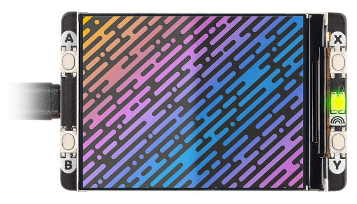
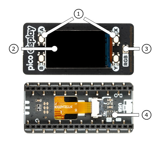
The PiMoroni Pico Display Pack (PIM543) [1] shield comes with the built-in controller ST7789 [35] inside the LCD, which is an LCD controller with 240 × RGB × 320 pixels, while the pixels of this 1.44-inch LCD itself is 135 (H) RGB × 240 (V). There are two types of horizontal and vertical screens, so the internal RAM of the LCD is not fully used. The LCD supports 12-bit, 16-bit, and 18-bit input color formats per pixel, namely RGB444, RGB565, and RGB666 three color formats. This integration uses the RGB565 color format, which is also a commonly used RGB format. The LCD uses a four-wire SPI communication interface.
Features and Resources |
Printed Circuit Board |
5V/40㎃ A B X Y R G B LCD 10 4 1
Design Data |

|
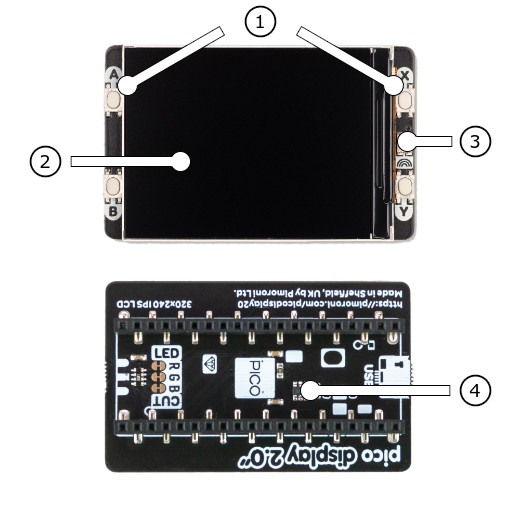
The PiMoroni Pico Display Pack 2.0 (PIM580) [3] shield comes with the built-in controller ST7789 [35] inside the LCD, which is an LCD controller with 240 × RGB × 320 pixels, while the pixels of this 2-inch LCD itself is 240 (H) RGB × 320 (V). There are two types of horizontal and vertical screens, so the internal RAM of the LCD is not fully used. The LCD supports 12-bit, 16-bit, and 18-bit input color formats per pixel, namely RGB444, RGB565, and RGB666 three color formats. This integration uses the RGB565 color format, which is also a commonly used RGB format. The LCD uses a four-wire SPI communication interface.
Features and Resources |
Printed Circuit Board |
5V/40㎃ A B X Y R G B LCD 11 4 1
Design Data |
|
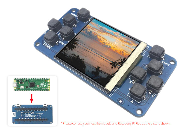
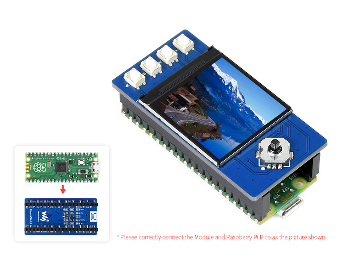
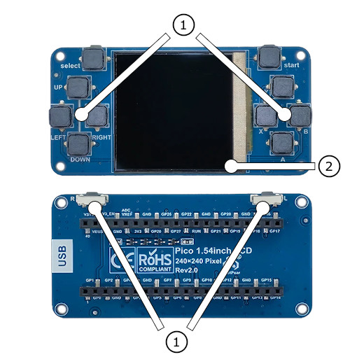
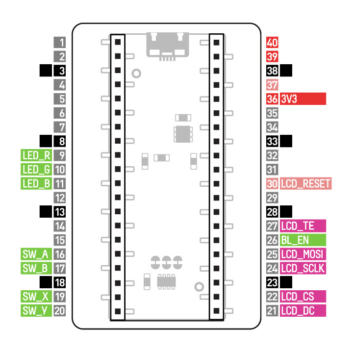
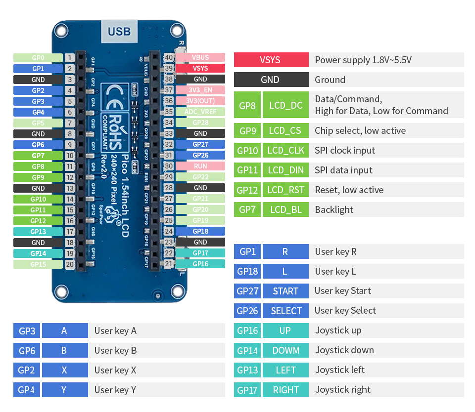
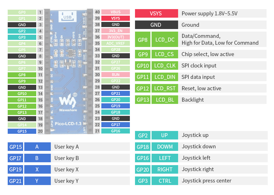
The Spotpear Pico LCD 1.54 [5] shield comes with the built-in controller ST7789 [35] inside the LCD, which is an LCD controller with 240 × RGB × 320 pixels, while the pixels of this 1.54-inch LCD itself is 240 (H) RGB × 240 (V). There are two types of horizontal and vertical screens, so the internal RAM of the LCD is not fully used. The LCD supports 12-bit, 16-bit, and 18-bit input color formats per pixel, namely RGB444, RGB565, and RGB666 three color formats. This integration uses the RGB565 color format, which is also a commonly used RGB format. The LCD uses a four-wire SPI communication interface.
Attention
Only the new Blue 1.54inch LCD labeled with Rev 2.0 is supported!
Features and Resources |
Printed Circuit Board |
5V/40㎃ A B X Y R L START SELECT UP|DOWN|LEFT|RIGHT LCD 16 1 1
Design Data |
|
Features and Resources |
Printed Circuit Board |
5V/40㎃ A B UP|DOWN|LEFT|RIGHT|ENTER LCD 12 1 1
Design Data |
|
Features and Resources |
Printed Circuit Board |
5V/40㎃ A B UP|DOWN|LEFT|RIGHT|ENTER LCD 12 1 1
Design Data |
|
Features and Resources |
Printed Circuit Board |
5V/40㎃ A B X Y UP|DOWN|LEFT|RIGHT|ENTER LCD 14 1 1
Design Data |
|
Features and Resources |
Printed Circuit Board |
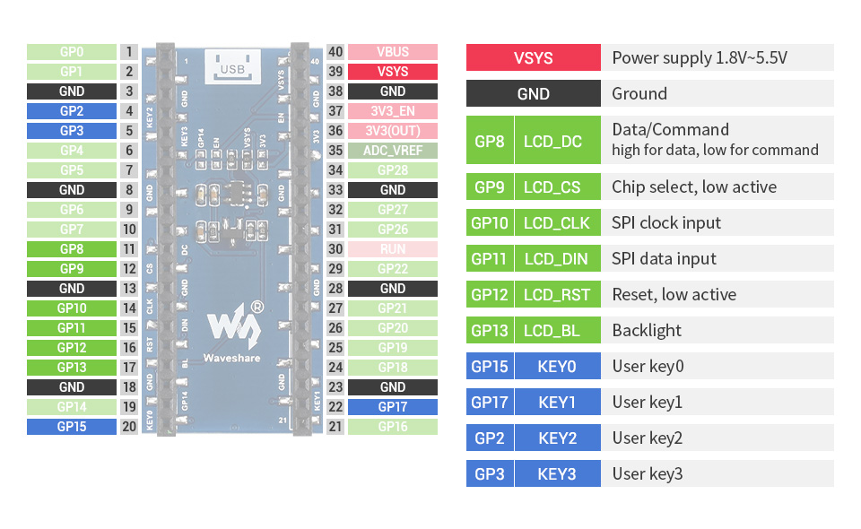
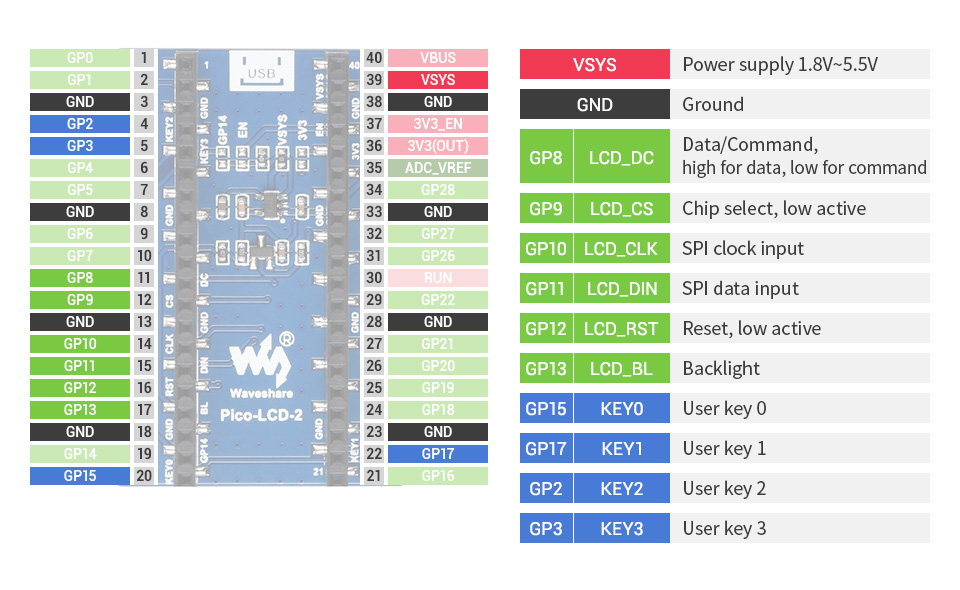
5V/40㎃ 0 1 2 3 LCD 9 1 1
Design Data |

|
Features and Resources |
Printed Circuit Board |
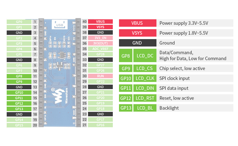
5V/40㎃ LCD 5 1 1
Design Data |
|
Features and Resources |
Printed Circuit Board |
5V/40㎃ 0 1 2 3 LCD 9 1 1
Design Data |
|
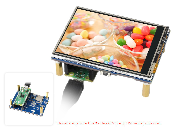
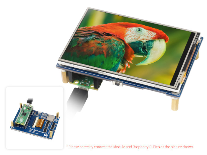
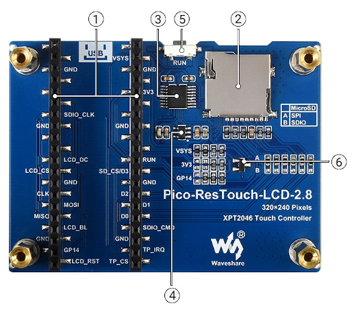
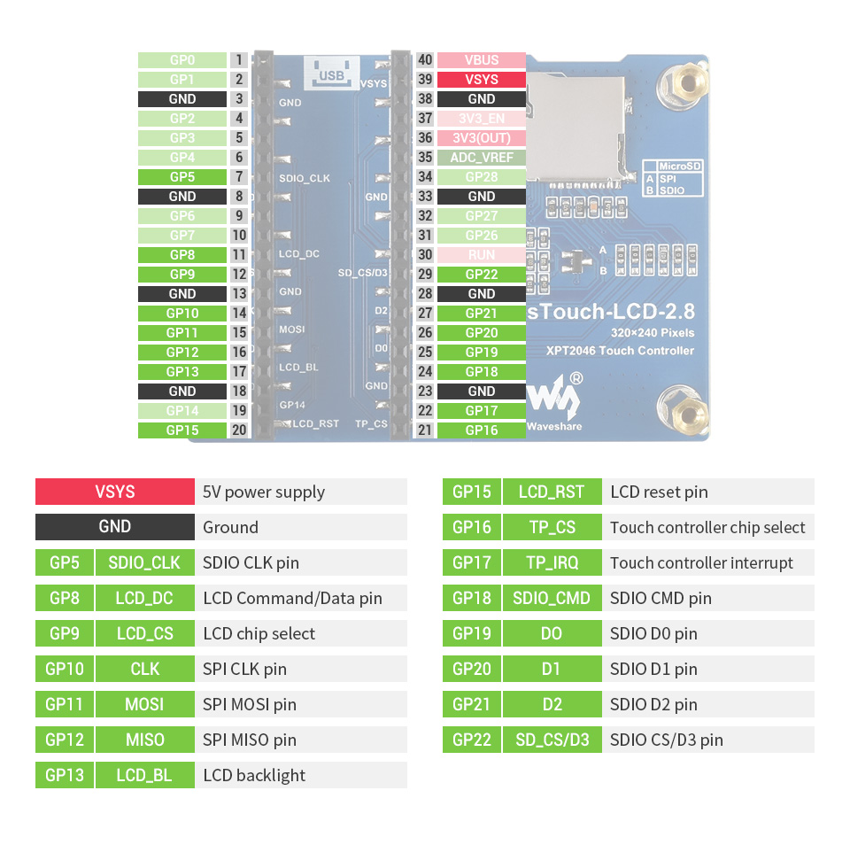
Additional there are a resistive Touch Screen (TS) with the TS controller XPT2046 [43] and a standard TF/microSD card slot.
Features and Resources |
Printed Circuit Board |
5V/40㎃ LCD/TSC TF/microSD 8 1 1 1 1
Design Data |
|
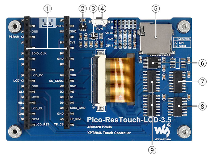
Additional there are a resistive Touch Screen (TS) with the TS controller XPT2046 [43] and a standard TF/microSD card slot. The board is prepared for retrofitting the JEDEC compliant Pseudo-Static RAM (PSRAM) chip, e.g. the ESP-PSRAM64H [49] by Espressif, which is also connected to the SPI.
Features and Resources |
Printed Circuit Board |
5V/40㎃ LCD/TSC TF/microSD 9 1 1 1 1
Design Data |
|
Positions
|
|---|
Inputs:
Outputs:
|
Data Sheets
|
|---|
Inputs:
Outputs:
|
Data Sheets
|
|---|
Inputs:
Outputs:
|
Data Sheets
|
|---|
Inputs:
Outputs:
|
Data Sheets
|
|---|
Inputs:
Outputs:
|
Data Sheets

|
|---|
Inputs:
Outputs:
|
Data Sheets
|
|---|
Inputs:
Outputs:
|
Data Sheets
|
|---|
|
Data Sheets
|
|---|
Inputs:
Outputs:
|
Data Sheets
|
|---|
|
Data Sheets
|
|---|
|
Data Sheets
JEDEC compliant PSRAM
Above 74HC4040 (position 7) is the spare SOP8 footprint for an optional serial PSRAM, which is also connected to the SPI. Possible 3.0~3.3V types [49] are:
Pinouts
Pin Mapping |
Pinout |
Default Zephyr Peripheral Mapping
Devicetree compatible |
|
Pin Mapping |
Pinout |
Default Zephyr Peripheral Mapping
Devicetree compatible |
|
Pin Mapping |
Pinout |
Default Zephyr Peripheral Mapping
Devicetree compatible |
|
Pin Mapping |
Pinout |
Default Zephyr Peripheral Mapping
Devicetree compatible |
|
Pin Mapping |
Pinout |
Default Zephyr Peripheral Mapping
Devicetree compatible |
|
Pin Mapping |
Pinout |
Default Zephyr Peripheral Mapping
Devicetree compatible |
|
Pin Mapping |
Pinout |
Default Zephyr Peripheral Mapping
Devicetree compatible |
|
Pin Mapping |
Pinout |
Default Zephyr Peripheral Mapping
Devicetree compatible |
|
Pin Mapping |
Pinout |
Default Zephyr Peripheral Mapping
Devicetree compatible |
|
Pin Mapping |
Pinout |
Default Zephyr Peripheral Mapping
Devicetree compatible |
|
Pin Mapping |
Pinout |
Default Zephyr Peripheral Mapping
Devicetree compatible |

|
Utilization
This shields can be used with any development board, shield, or snippet that
provides a Devicetree node with the raspberrypi,pico-header-r3
property for the compatibility. In particular, one SPI bus and some GPIO
signals on this edge connector must be free for communication with the LCD
on the shields. The shields also provide the special Devicetree labels
&rpipico_spi_lcd and &lcd_panel for this purpose.
For shields with touchscreen support, additional GPIO signals and on occasion
one I2C bus on the edge connector must also be free for communication with the
touchscreen controller on the shield. Then the shields also provide the special
Devicetree labels &rpipico_spi_tsc and &tsc_panel
for this purpose.
For shields with TF/microSD card slot, even more GPIO signals on the edge
connector must be free for communication with the card on the shield over
SDHC/SPI. The shields also provide the special Devicetree labels
&rpipico_spi_sdc and &sdhc_spi for this purpose.
In case of the SDHC/SDIO mode up to seven additional GPIO signals must be
free for communication with the card over a 4-bit SDHC/SDIO interface.
But this is not yet supported and may need changes on the shield hardware.
Programming
Set -DSHIELD=pimoroni_pico_lcd_1_44 and use optional the
USB Console Snippet (usb-console) when you invoke west build.
For example:
Using west:
west build -b rpi_pico -p -S usb-console --shield "pimoroni_pico_lcd_1_44" -d build/pimoroni_pico_lcd_1_44-helloshell bridle/samples/helloshell
west flash -r uf2 -d build/pimoroni_pico_lcd_1_44-helloshell
Using CMake and ninja:
# Use cmake to configure a Ninja-based buildsystem:
cmake -Bbuild/pimoroni_pico_lcd_1_44-helloshell -GNinja -DBOARD=rpi_pico -DSHIELD=""pimoroni_pico_lcd_1_44"" bridle/samples/helloshell

# Now run the build tool on the generated build system:
ninja -Cbuild/pimoroni_pico_lcd_1_44-helloshell flash
Simple test execution on target
(text in bold is a command input)
uart:~$ hello -h
hello - say hello
uart:~$ hello
Hello from shell.
uart:~$ hwinfo devid
Length: 8
ID: 0x8c998be1de969148

uart:~$ kernel version
Zephyr version 4.1.0

uart:~$ bridle version
Bridle version 4.1.0

uart:~$ bridle version long
Bridle version 4.1.0.0

uart:~$ bridle info
Zephyr: 4.1.0
Bridle: 4.1.0
uart:~$ device list
devices:
- clock-controller@40008000 (READY)
  DT node labels: clocks
- reset-controller@4000c000 (READY)
  DT node labels: reset
- snippet_cdc_acm_console_uart (READY)
  DT node labels: snippet_cdc_acm_console_uart
- uart@40034000 (READY)
  DT node labels: uart0 pico_serial rpipico_serial
- timer@40054000 (READY)
  DT node labels: timer
- gpio@40014000 (READY)
  DT node labels: gpio0
- adc@4004c000 (READY)
  DT node labels: adc
- flash-controller@18000000 (READY)
  DT node labels: ssi
- i2c@40044000 (READY)
  DT node labels: i2c0 pico_i2c pico_i2c0 rpipico_i2c rpipico_i2c0
- pwm@40050000 (READY)
  DT node labels: pwm pico_pwm rpipico_pwm
- vreg@40064000 (READY)
  DT node labels: vreg
- rtc@4005c000 (READY)
  DT node labels: rtc
- lcd-backlight-en (READY)
  DT node labels: lcd_backlight_en
- gpio_leds (READY)
  DT node labels: gpio_leds
- leds (READY)
uart:~$ history
[  0] history
[  1] device list
[  2] bridle info
[  3] bridle version long
[  4] bridle version
[  5] kernel version
[  6] hwinfo devid
[  7] hello
[  8] hello -h
Operate with the LCD backlight LED BL_EN at GP20:
uart:~$ regulator disable lcd-backlight-en
uart:~$ regulator enable lcd-backlight-en
Operate with the user button SW_X at GP14:
uart:~$ gpio get gpio@40014000 14
0

uart:~$ gpio conf gpio@40014000 14 iul
uart:~$ gpio get gpio@40014000 14
0
uart:~$ gpio get gpio@40014000 14
1
uart:~$ gpio get gpio@40014000 3
0
Operate with the test LED LED_B at GP8:
uart:~$ led on gpio_leds 2
gpio_leds: turning on LED 2
uart:~$ led off gpio_leds 2
gpio_leds: turning off LED 2
Using west:
west build -b rpi_pico/rp2040/w -p -S usb-console --shield "pimoroni_pico_lcd_1_44" -d build/pimoroni_pico_lcd_1_44-helloshell bridle/samples/helloshell
west flash -r uf2 -d build/pimoroni_pico_lcd_1_44-helloshell
Using CMake and ninja:
# Use cmake to configure a Ninja-based buildsystem:
cmake -Bbuild/pimoroni_pico_lcd_1_44-helloshell -GNinja -DBOARD=rpi_pico/rp2040/w -DSHIELD=""pimoroni_pico_lcd_1_44"" bridle/samples/helloshell

# Now run the build tool on the generated build system:
ninja -Cbuild/pimoroni_pico_lcd_1_44-helloshell flash
Simple test execution on target
(text in bold is a command input)
uart:~$ hello -h
hello - say hello
uart:~$ hello
Hello from shell.
uart:~$ hwinfo devid
Length: 8
ID: 0x8c998be1de969148

uart:~$ kernel version
Zephyr version 4.1.0

uart:~$ bridle version
Bridle version 4.1.0

uart:~$ bridle version long
Bridle version 4.1.0.0

uart:~$ bridle info
Zephyr: 4.1.0
Bridle: 4.1.0
uart:~$ device list
devices:
- clock-controller@40008000 (READY)
  DT node labels: clocks
- reset-controller@4000c000 (READY)
  DT node labels: reset
- snippet_cdc_acm_console_uart (READY)
  DT node labels: snippet_cdc_acm_console_uart
- uart@40034000 (READY)
  DT node labels: uart0 pico_serial rpipico_serial
- timer@40054000 (READY)
  DT node labels: timer
- gpio@40014000 (READY)
  DT node labels: gpio0
- adc@4004c000 (READY)
  DT node labels: adc
- flash-controller@18000000 (READY)
  DT node labels: ssi
- i2c@40044000 (READY)
  DT node labels: i2c0 pico_i2c pico_i2c0 rpipico_i2c rpipico_i2c0
- pwm@40050000 (READY)
  DT node labels: pwm pico_pwm rpipico_pwm
- vreg@40064000 (READY)
  DT node labels: vreg
- rtc@4005c000 (READY)
  DT node labels: rtc
- lcd-backlight-en (READY)
  DT node labels: lcd_backlight_en
- gpio_leds (READY)
  DT node labels: gpio_leds
- leds (READY)
uart:~$ history
[  0] history
[  1] device list
[  2] bridle info
[  3] bridle version long
[  4] bridle version
[  5] kernel version
[  6] hwinfo devid
[  7] hello
[  8] hello -h
Operate with the LCD backlight LED BL_EN at GP20:
uart:~$ regulator disable lcd-backlight-en
uart:~$ regulator enable lcd-backlight-en
Operate with the user button SW_X at GP14:
uart:~$ gpio get gpio@40014000 14
0

uart:~$ gpio conf gpio@40014000 14 iul
uart:~$ gpio get gpio@40014000 14
0
uart:~$ gpio get gpio@40014000 14
1
uart:~$ gpio get gpio@40014000 3
0
Operate with the test LED LED_B at GP8:
uart:~$ led on gpio_leds 2
gpio_leds: turning on LED 2
uart:~$ led off gpio_leds 2
gpio_leds: turning off LED 2
on standard 4㎆ revision
Using west:
west build -b waveshare_rp2040_plus -p -S usb-console --shield "pimoroni_pico_lcd_1_44" -d build/pimoroni_pico_lcd_1_44-helloshell bridle/samples/helloshell
west flash -r uf2 -d build/pimoroni_pico_lcd_1_44-helloshell
Using CMake and ninja:
# Use cmake to configure a Ninja-based buildsystem:
cmake -Bbuild/pimoroni_pico_lcd_1_44-helloshell -GNinja -DBOARD=waveshare_rp2040_plus -DSHIELD=""pimoroni_pico_lcd_1_44"" bridle/samples/helloshell

# Now run the build tool on the generated build system:
ninja -Cbuild/pimoroni_pico_lcd_1_44-helloshell flash
on extended 16㎆ revision
Using west:
west build -b waveshare_rp2040_plus@16mb -p -S usb-console --shield "pimoroni_pico_lcd_1_44" -d build/pimoroni_pico_lcd_1_44-helloshell bridle/samples/helloshell
west flash -r uf2 -d build/pimoroni_pico_lcd_1_44-helloshell
Using CMake and ninja:
# Use cmake to configure a Ninja-based buildsystem:
cmake -Bbuild/pimoroni_pico_lcd_1_44-helloshell -GNinja -DBOARD=waveshare_rp2040_plus@16mb -DSHIELD=""pimoroni_pico_lcd_1_44"" bridle/samples/helloshell

# Now run the build tool on the generated build system:
ninja -Cbuild/pimoroni_pico_lcd_1_44-helloshell flash
Simple test execution on target
(text in bold is a command input)
uart:~$ hello -h
hello - say hello
uart:~$ hello
Hello from shell.
uart:~$ hwinfo devid
Length: 8
ID: 0x8c998be1de969148

uart:~$ kernel version
Zephyr version 4.1.0

uart:~$ bridle version
Bridle version 4.1.0

uart:~$ bridle version long
Bridle version 4.1.0.0

uart:~$ bridle info
Zephyr: 4.1.0
Bridle: 4.1.0
uart:~$ device list
devices:
- clock-controller@40008000 (READY)
  DT node labels: clocks
- reset-controller@4000c000 (READY)
  DT node labels: reset
- snippet_cdc_acm_console_uart (READY)
  DT node labels: snippet_cdc_acm_console_uart
- uart@40034000 (READY)
  DT node labels: uart0 pico_serial rpipico_serial
- timer@40054000 (READY)
  DT node labels: timer
- gpio@40014000 (READY)
  DT node labels: gpio0
- adc@4004c000 (READY)
  DT node labels: adc
- flash-controller@18000000 (READY)
  DT node labels: ssi
- i2c@40044000 (READY)
  DT node labels: i2c0 pico_i2c pico_i2c0 rpipico_i2c rpipico_i2c0
- pwm@40050000 (READY)
  DT node labels: pwm pico_pwm rpipico_pwm
- vreg@40064000 (READY)
  DT node labels: vreg
- rtc@4005c000 (READY)
  DT node labels: rtc
- lcd-backlight-en (READY)
  DT node labels: lcd_backlight_en
- gpio_leds (READY)
  DT node labels: gpio_leds
- leds (READY)
uart:~$ history
[  0] history
[  1] device list
[  2] bridle info
[  3] bridle version long
[  4] bridle version
[  5] kernel version
[  6] hwinfo devid
[  7] hello
[  8] hello -h
Operate with the LCD backlight LED BL_EN at GP20:
uart:~$ regulator disable lcd-backlight-en
uart:~$ regulator enable lcd-backlight-en
Operate with the user button SW_X at GP14:
uart:~$ gpio get gpio@40014000 14
0

uart:~$ gpio conf gpio@40014000 14 iul
uart:~$ gpio get gpio@40014000 14
0
uart:~$ gpio get gpio@40014000 14
1
uart:~$ gpio get gpio@40014000 3
0
Operate with the test LED LED_B at GP8:
uart:~$ led on gpio_leds 2
gpio_leds: turning on LED 2
uart:~$ led off gpio_leds 2
gpio_leds: turning off LED 2
Set -DSHIELD=pimoroni_pico_lcd_2 and use optional the
USB Console Snippet (usb-console) when you invoke west build.
For example:
Using west:
west build -b rpi_pico -p -S usb-console --shield "pimoroni_pico_lcd_2" -d build/pimoroni_pico_lcd_2-helloshell bridle/samples/helloshell
west flash -r uf2 -d build/pimoroni_pico_lcd_2-helloshell
Using CMake and ninja:
# Use cmake to configure a Ninja-based buildsystem:
cmake -Bbuild/pimoroni_pico_lcd_2-helloshell -GNinja -DBOARD=rpi_pico -DSHIELD=""pimoroni_pico_lcd_2"" bridle/samples/helloshell

# Now run the build tool on the generated build system:
ninja -Cbuild/pimoroni_pico_lcd_2-helloshell flash
Simple test execution on target
(text in bold is a command input)
uart:~$ hello -h
hello - say hello
uart:~$ hello
Hello from shell.
uart:~$ hwinfo devid
Length: 8
ID: 0x8c998be1de969148

uart:~$ kernel version
Zephyr version 4.1.0

uart:~$ bridle version
Bridle version 4.1.0

uart:~$ bridle version long
Bridle version 4.1.0.0

uart:~$ bridle info
Zephyr: 4.1.0
Bridle: 4.1.0
uart:~$ device list
devices:
- clock-controller@40008000 (READY)
  DT node labels: clocks
- reset-controller@4000c000 (READY)
  DT node labels: reset
- snippet_cdc_acm_console_uart (READY)
  DT node labels: snippet_cdc_acm_console_uart
- uart@40034000 (READY)
  DT node labels: uart0 pico_serial rpipico_serial
- timer@40054000 (READY)
  DT node labels: timer
- gpio@40014000 (READY)
  DT node labels: gpio0
- adc@4004c000 (READY)
  DT node labels: adc
- flash-controller@18000000 (READY)
  DT node labels: ssi
- i2c@40044000 (READY)
  DT node labels: i2c0 pico_i2c pico_i2c0 rpipico_i2c rpipico_i2c0
- pwm@40050000 (READY)
  DT node labels: pwm pico_pwm rpipico_pwm
- vreg@40064000 (READY)
  DT node labels: vreg
- rtc@4005c000 (READY)
  DT node labels: rtc
- lcd-backlight-en (READY)
  DT node labels: lcd_backlight_en
- gpio_leds (READY)
  DT node labels: gpio_leds
- leds (READY)
uart:~$ history
[  0] history
[  1] device list
[  2] bridle info
[  3] bridle version long
[  4] bridle version
[  5] kernel version
[  6] hwinfo devid
[  7] hello
[  8] hello -h
Operate with the LCD backlight LED BL_EN at GP20:
uart:~$ regulator disable lcd-backlight-en
uart:~$ regulator enable lcd-backlight-en
Operate with the user button SW_X at GP14:
uart:~$ gpio get gpio@40014000 14
0

uart:~$ gpio conf gpio@40014000 14 iul
uart:~$ gpio get gpio@40014000 14
0
uart:~$ gpio get gpio@40014000 14
1
uart:~$ gpio get gpio@40014000 3
0
Operate with the test LED LED_B at GP8:
uart:~$ led on gpio_leds 2
gpio_leds: turning on LED 2
uart:~$ led off gpio_leds 2
gpio_leds: turning off LED 2
Using west:
west build -b rpi_pico/rp2040/w -p -S usb-console --shield "pimoroni_pico_lcd_2" -d build/pimoroni_pico_lcd_2-helloshell bridle/samples/helloshell
west flash -r uf2 -d build/pimoroni_pico_lcd_2-helloshell
Using CMake and ninja:
# Use cmake to configure a Ninja-based buildsystem:
cmake -Bbuild/pimoroni_pico_lcd_2-helloshell -GNinja -DBOARD=rpi_pico/rp2040/w -DSHIELD=""pimoroni_pico_lcd_2"" bridle/samples/helloshell

# Now run the build tool on the generated build system:
ninja -Cbuild/pimoroni_pico_lcd_2-helloshell flash
Simple test execution on target
(text in bold is a command input)
uart:~$ hello -h
hello - say hello
uart:~$ hello
Hello from shell.
uart:~$ hwinfo devid
Length: 8
ID: 0x8c998be1de969148

uart:~$ kernel version
Zephyr version 4.1.0

uart:~$ bridle version
Bridle version 4.1.0

uart:~$ bridle version long
Bridle version 4.1.0.0

uart:~$ bridle info
Zephyr: 4.1.0
Bridle: 4.1.0
uart:~$ device list
devices:
- clock-controller@40008000 (READY)
  DT node labels: clocks
- reset-controller@4000c000 (READY)
  DT node labels: reset
- snippet_cdc_acm_console_uart (READY)
  DT node labels: snippet_cdc_acm_console_uart
- uart@40034000 (READY)
  DT node labels: uart0 pico_serial rpipico_serial
- timer@40054000 (READY)
  DT node labels: timer
- gpio@40014000 (READY)
  DT node labels: gpio0
- adc@4004c000 (READY)
  DT node labels: adc
- flash-controller@18000000 (READY)
  DT node labels: ssi
- i2c@40044000 (READY)
  DT node labels: i2c0 pico_i2c pico_i2c0 rpipico_i2c rpipico_i2c0
- pwm@40050000 (READY)
  DT node labels: pwm pico_pwm rpipico_pwm
- vreg@40064000 (READY)
  DT node labels: vreg
- rtc@4005c000 (READY)
  DT node labels: rtc
- lcd-backlight-en (READY)
  DT node labels: lcd_backlight_en
- gpio_leds (READY)
  DT node labels: gpio_leds
- leds (READY)
uart:~$ history
[  0] history
[  1] device list
[  2] bridle info
[  3] bridle version long
[  4] bridle version
[  5] kernel version
[  6] hwinfo devid
[  7] hello
[  8] hello -h
Operate with the LCD backlight LED BL_EN at GP20:
uart:~$ regulator disable lcd-backlight-en
uart:~$ regulator enable lcd-backlight-en
Operate with the user button SW_X at GP14:
uart:~$ gpio get gpio@40014000 14
0

uart:~$ gpio conf gpio@40014000 14 iul
uart:~$ gpio get gpio@40014000 14
0
uart:~$ gpio get gpio@40014000 14
1
uart:~$ gpio get gpio@40014000 3
0
Operate with the test LED LED_B at GP8:
uart:~$ led on gpio_leds 2
gpio_leds: turning on LED 2
uart:~$ led off gpio_leds 2
gpio_leds: turning off LED 2
on standard 4㎆ revision
Using west:
west build -b waveshare_rp2040_plus -p -S usb-console --shield "pimoroni_pico_lcd_2" -d build/pimoroni_pico_lcd_2-helloshell bridle/samples/helloshell
west flash -r uf2 -d build/pimoroni_pico_lcd_2-helloshell
Using CMake and ninja:
# Use cmake to configure a Ninja-based buildsystem:
cmake -Bbuild/pimoroni_pico_lcd_2-helloshell -GNinja -DBOARD=waveshare_rp2040_plus -DSHIELD=""pimoroni_pico_lcd_2"" bridle/samples/helloshell

# Now run the build tool on the generated build system:
ninja -Cbuild/pimoroni_pico_lcd_2-helloshell flash
on extended 16㎆ revision
Using west:
west build -b waveshare_rp2040_plus@16mb -p -S usb-console --shield "pimoroni_pico_lcd_2" -d build/pimoroni_pico_lcd_2-helloshell bridle/samples/helloshell
west flash -r uf2 -d build/pimoroni_pico_lcd_2-helloshell
Using CMake and ninja:
# Use cmake to configure a Ninja-based buildsystem:
cmake -Bbuild/pimoroni_pico_lcd_2-helloshell -GNinja -DBOARD=waveshare_rp2040_plus@16mb -DSHIELD=""pimoroni_pico_lcd_2"" bridle/samples/helloshell

# Now run the build tool on the generated build system:
ninja -Cbuild/pimoroni_pico_lcd_2-helloshell flash
Simple test execution on target
(text in bold is a command input)
uart:~$ hello -h
hello - say hello
uart:~$ hello
Hello from shell.
uart:~$ hwinfo devid
Length: 8
ID: 0x8c998be1de969148

uart:~$ kernel version
Zephyr version 4.1.0

uart:~$ bridle version
Bridle version 4.1.0

uart:~$ bridle version long
Bridle version 4.1.0.0

uart:~$ bridle info
Zephyr: 4.1.0
Bridle: 4.1.0
uart:~$ device list
devices:
- clock-controller@40008000 (READY)
  DT node labels: clocks
- reset-controller@4000c000 (READY)
  DT node labels: reset
- snippet_cdc_acm_console_uart (READY)
  DT node labels: snippet_cdc_acm_console_uart
- uart@40034000 (READY)
  DT node labels: uart0 pico_serial rpipico_serial
- timer@40054000 (READY)
  DT node labels: timer
- gpio@40014000 (READY)
  DT node labels: gpio0
- adc@4004c000 (READY)
  DT node labels: adc
- flash-controller@18000000 (READY)
  DT node labels: ssi
- i2c@40044000 (READY)
  DT node labels: i2c0 pico_i2c pico_i2c0 rpipico_i2c rpipico_i2c0
- pwm@40050000 (READY)
  DT node labels: pwm pico_pwm rpipico_pwm
- vreg@40064000 (READY)
  DT node labels: vreg
- rtc@4005c000 (READY)
  DT node labels: rtc
- lcd-backlight-en (READY)
  DT node labels: lcd_backlight_en
- gpio_leds (READY)
  DT node labels: gpio_leds
- leds (READY)
uart:~$ history
[  0] history
[  1] device list
[  2] bridle info
[  3] bridle version long
[  4] bridle version
[  5] kernel version
[  6] hwinfo devid
[  7] hello
[  8] hello -h
Operate with the LCD backlight LED BL_EN at GP20:
uart:~$ regulator disable lcd-backlight-en
uart:~$ regulator enable lcd-backlight-en
Operate with the user button SW_X at GP14:
uart:~$ gpio get gpio@40014000 14
0

uart:~$ gpio conf gpio@40014000 14 iul
uart:~$ gpio get gpio@40014000 14
0
uart:~$ gpio get gpio@40014000 14
1
uart:~$ gpio get gpio@40014000 3
0
Operate with the test LED LED_B at GP8:
uart:~$ led on gpio_leds 2
gpio_leds: turning on LED 2
uart:~$ led off gpio_leds 2
gpio_leds: turning off LED 2
Set -DSHIELD=spotpear_pico_lcd_1_54 and use optional the
USB Console Snippet (usb-console) when you invoke west build.
For example:
Using west:
west build -b rpi_pico -p -S usb-console --shield "spotpear_pico_lcd_1_54" -d build/spotpear_pico_lcd_1_54-helloshell bridle/samples/helloshell
west flash -r uf2 -d build/spotpear_pico_lcd_1_54-helloshell
Using CMake and ninja:
# Use cmake to configure a Ninja-based buildsystem:
cmake -Bbuild/spotpear_pico_lcd_1_54-helloshell -GNinja -DBOARD=rpi_pico -DSHIELD=""spotpear_pico_lcd_1_54"" bridle/samples/helloshell

# Now run the build tool on the generated build system:
ninja -Cbuild/spotpear_pico_lcd_1_54-helloshell flash
Simple test execution on target
(text in bold is a command input)
uart:~$ hello -h
hello - say hello
uart:~$ hello
Hello from shell.
uart:~$ hwinfo devid
Length: 8
ID: 0x8c998be1de969148

uart:~$ kernel version
Zephyr version 4.1.0

uart:~$ bridle version
Bridle version 4.1.0

uart:~$ bridle version long
Bridle version 4.1.0.0

uart:~$ bridle info
Zephyr: 4.1.0
Bridle: 4.1.0
uart:~$ device list
devices:
- clock-controller@40008000 (READY)
  DT node labels: clocks
- reset-controller@4000c000 (READY)
  DT node labels: reset
- snippet_cdc_acm_console_uart (READY)
  DT node labels: snippet_cdc_acm_console_uart
- uart@40034000 (READY)
  DT node labels: uart0 pico_serial rpipico_serial
- timer@40054000 (READY)
  DT node labels: timer
- gpio@40014000 (READY)
  DT node labels: gpio0
- adc@4004c000 (READY)
  DT node labels: adc
- flash-controller@18000000 (READY)
  DT node labels: ssi
- i2c@40044000 (READY)
  DT node labels: i2c0 pico_i2c pico_i2c0 rpipico_i2c rpipico_i2c0
- vreg@40064000 (READY)
  DT node labels: vreg
- rtc@4005c000 (READY)
  DT node labels: rtc
- lcd-backlight-en (READY)
  DT node labels: lcd_backlight_en
- leds (READY)
uart:~$ history
[  0] history
[  1] device list
[  2] bridle info
[  3] bridle version long
[  4] bridle version
[  5] kernel version
[  6] hwinfo devid
[  7] hello
[  8] hello -h
Operate with the LCD backlight LED LCD_BL at GP7:
uart:~$ regulator disable lcd-backlight-en
uart:~$ regulator enable lcd-backlight-en
Operate with the joystick button SELECT at GP26:
uart:~$ gpio get gpio@40014000 26
1

uart:~$ gpio conf gpio@40014000 26 iul
uart:~$ gpio get gpio@40014000 26
0
uart:~$ gpio get gpio@40014000 26
1
uart:~$ gpio get gpio@40014000 26
0
Using west:
west build -b rpi_pico/rp2040/w -p -S usb-console --shield "spotpear_pico_lcd_1_54" -d build/spotpear_pico_lcd_1_54-helloshell bridle/samples/helloshell
west flash -r uf2 -d build/spotpear_pico_lcd_1_54-helloshell
Using CMake and ninja:
# Use cmake to configure a Ninja-based buildsystem:
cmake -Bbuild/spotpear_pico_lcd_1_54-helloshell -GNinja -DBOARD=rpi_pico/rp2040/w -DSHIELD=""spotpear_pico_lcd_1_54"" bridle/samples/helloshell

# Now run the build tool on the generated build system:
ninja -Cbuild/spotpear_pico_lcd_1_54-helloshell flash
Simple test execution on target
(text in bold is a command input)
uart:~$ hello -h
hello - say hello
uart:~$ hello
Hello from shell.
uart:~$ hwinfo devid
Length: 8
ID: 0x8c998be1de969148

uart:~$ kernel version
Zephyr version 4.1.0

uart:~$ bridle version
Bridle version 4.1.0

uart:~$ bridle version long
Bridle version 4.1.0.0

uart:~$ bridle info
Zephyr: 4.1.0
Bridle: 4.1.0
uart:~$ device list
devices:
- clock-controller@40008000 (READY)
  DT node labels: clocks
- reset-controller@4000c000 (READY)
  DT node labels: reset
- snippet_cdc_acm_console_uart (READY)
  DT node labels: snippet_cdc_acm_console_uart
- uart@40034000 (READY)
  DT node labels: uart0 pico_serial rpipico_serial
- timer@40054000 (READY)
  DT node labels: timer
- gpio@40014000 (READY)
  DT node labels: gpio0
- adc@4004c000 (READY)
  DT node labels: adc
- flash-controller@18000000 (READY)
  DT node labels: ssi
- i2c@40044000 (READY)
  DT node labels: i2c0 pico_i2c pico_i2c0 rpipico_i2c rpipico_i2c0
- vreg@40064000 (READY)
  DT node labels: vreg
- rtc@4005c000 (READY)
  DT node labels: rtc
- lcd-backlight-en (READY)
  DT node labels: lcd_backlight_en
- leds (READY)
uart:~$ history
[  0] history
[  1] device list
[  2] bridle info
[  3] bridle version long
[  4] bridle version
[  5] kernel version
[  6] hwinfo devid
[  7] hello
[  8] hello -h
Operate with the LCD backlight LED LCD_BL at GP7:
uart:~$ regulator disable lcd-backlight-en
uart:~$ regulator enable lcd-backlight-en
Operate with the joystick button SELECT at GP26:
uart:~$ gpio get gpio@40014000 26
1

uart:~$ gpio conf gpio@40014000 26 iul
uart:~$ gpio get gpio@40014000 26
0
uart:~$ gpio get gpio@40014000 26
1
uart:~$ gpio get gpio@40014000 26
0
on standard 4㎆ revision
Using west:
west build -b waveshare_rp2040_plus -p -S usb-console --shield "spotpear_pico_lcd_1_54" -d build/spotpear_pico_lcd_1_54-helloshell bridle/samples/helloshell
west flash -r uf2 -d build/spotpear_pico_lcd_1_54-helloshell
Using CMake and ninja:
# Use cmake to configure a Ninja-based buildsystem:
cmake -Bbuild/spotpear_pico_lcd_1_54-helloshell -GNinja -DBOARD=waveshare_rp2040_plus -DSHIELD=""spotpear_pico_lcd_1_54"" bridle/samples/helloshell

# Now run the build tool on the generated build system:
ninja -Cbuild/spotpear_pico_lcd_1_54-helloshell flash
on extended 16㎆ revision
Using west:
west build -b waveshare_rp2040_plus@16mb -p -S usb-console --shield "spotpear_pico_lcd_1_54" -d build/spotpear_pico_lcd_1_54-helloshell bridle/samples/helloshell
west flash -r uf2 -d build/spotpear_pico_lcd_1_54-helloshell
Using CMake and ninja:
# Use cmake to configure a Ninja-based buildsystem:
cmake -Bbuild/spotpear_pico_lcd_1_54-helloshell -GNinja -DBOARD=waveshare_rp2040_plus@16mb -DSHIELD=""spotpear_pico_lcd_1_54"" bridle/samples/helloshell

# Now run the build tool on the generated build system:
ninja -Cbuild/spotpear_pico_lcd_1_54-helloshell flash
Simple test execution on target
(text in bold is a command input)
uart:~$ hello -h
hello - say hello
uart:~$ hello
Hello from shell.
uart:~$ hwinfo devid
Length: 8
ID: 0x8c998be1de969148

uart:~$ kernel version
Zephyr version 4.1.0

uart:~$ bridle version
Bridle version 4.1.0

uart:~$ bridle version long
Bridle version 4.1.0.0

uart:~$ bridle info
Zephyr: 4.1.0
Bridle: 4.1.0
uart:~$ device list
devices:
- clock-controller@40008000 (READY)
  DT node labels: clocks
- reset-controller@4000c000 (READY)
  DT node labels: reset
- snippet_cdc_acm_console_uart (READY)
  DT node labels: snippet_cdc_acm_console_uart
- uart@40034000 (READY)
  DT node labels: uart0 pico_serial rpipico_serial
- timer@40054000 (READY)
  DT node labels: timer
- gpio@40014000 (READY)
  DT node labels: gpio0
- adc@4004c000 (READY)
  DT node labels: adc
- flash-controller@18000000 (READY)
  DT node labels: ssi
- i2c@40044000 (READY)
  DT node labels: i2c0 pico_i2c pico_i2c0 rpipico_i2c rpipico_i2c0
- vreg@40064000 (READY)
  DT node labels: vreg
- rtc@4005c000 (READY)
  DT node labels: rtc
- lcd-backlight-en (READY)
  DT node labels: lcd_backlight_en
- leds (READY)
uart:~$ history
[  0] history
[  1] device list
[  2] bridle info
[  3] bridle version long
[  4] bridle version
[  5] kernel version
[  6] hwinfo devid
[  7] hello
[  8] hello -h
Operate with the LCD backlight LED LCD_BL at GP7:
uart:~$ regulator disable lcd-backlight-en
uart:~$ regulator enable lcd-backlight-en
Operate with the joystick button SELECT at GP26:
uart:~$ gpio get gpio@40014000 26
1

uart:~$ gpio conf gpio@40014000 26 iul
uart:~$ gpio get gpio@40014000 26
0
uart:~$ gpio get gpio@40014000 26
1
uart:~$ gpio get gpio@40014000 26
0
Set -DSHIELD=waveshare_pico_lcd_0_96 and use optional the
USB Console Snippet (usb-console) when you invoke west build.
For example:
Using west:
west build -b rpi_pico -p -S usb-console --shield "waveshare_pico_lcd_0_96" -d build/waveshare_pico_lcd_0_96-helloshell bridle/samples/helloshell
west flash -r uf2 -d build/waveshare_pico_lcd_0_96-helloshell
Using CMake and ninja:
# Use cmake to configure a Ninja-based buildsystem:
cmake -Bbuild/waveshare_pico_lcd_0_96-helloshell -GNinja -DBOARD=rpi_pico -DSHIELD=""waveshare_pico_lcd_0_96"" bridle/samples/helloshell

# Now run the build tool on the generated build system:
ninja -Cbuild/waveshare_pico_lcd_0_96-helloshell flash
Simple test execution on target
(text in bold is a command input)
uart:~$ hello -h
hello - say hello
uart:~$ hello
Hello from shell.
uart:~$ hwinfo devid
Length: 8
ID: 0x8c998be1de969148

uart:~$ kernel version
Zephyr version 4.1.0

uart:~$ bridle version
Bridle version 4.1.0

uart:~$ bridle version long
Bridle version 4.1.0.0

uart:~$ bridle info
Zephyr: 4.1.0
Bridle: 4.1.0
uart:~$ device list
devices:
- clock-controller@40008000 (READY)
  DT node labels: clocks
- reset-controller@4000c000 (READY)
  DT node labels: reset
- snippet_cdc_acm_console_uart (READY)
  DT node labels: snippet_cdc_acm_console_uart
- uart@40034000 (READY)
  DT node labels: uart0 pico_serial rpipico_serial
- timer@40054000 (READY)
  DT node labels: timer
- gpio@40014000 (READY)
  DT node labels: gpio0
- adc@4004c000 (READY)
  DT node labels: adc
- flash-controller@18000000 (READY)
  DT node labels: ssi
- i2c@40044000 (READY)
  DT node labels: i2c0 pico_i2c pico_i2c0 rpipico_i2c rpipico_i2c0
- vreg@40064000 (READY)
  DT node labels: vreg
- rtc@4005c000 (READY)
  DT node labels: rtc
- lcd-backlight-en (READY)
  DT node labels: lcd_backlight_en
- leds (READY)
uart:~$ history
[  0] history
[  1] device list
[  2] bridle info
[  3] bridle version long
[  4] bridle version
[  5] kernel version
[  6] hwinfo devid
[  7] hello
[  8] hello -h
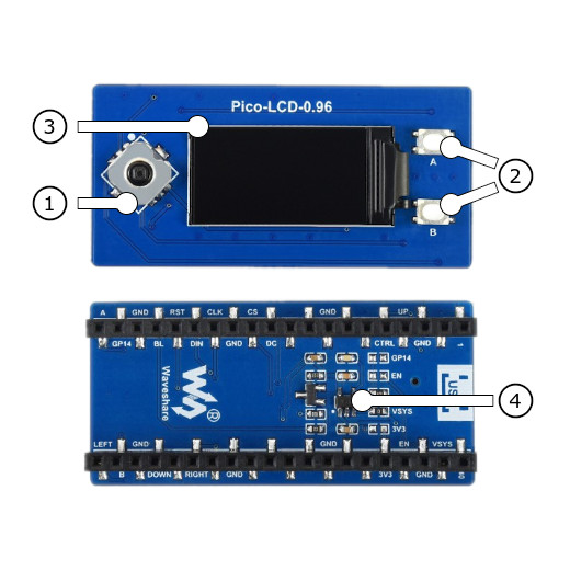
Operate with the LCD backlight LED LCD_BL at GP13:
uart:~$ regulator disable lcd-backlight-en
uart:~$ regulator enable lcd-backlight-en
Operate with the joystick button ENTER at GP3:
uart:~$ gpio get gpio@40014000 3
0

uart:~$ gpio conf gpio@40014000 3 iul
uart:~$ gpio get gpio@40014000 3
0
uart:~$ gpio get gpio@40014000 3
1
uart:~$ gpio get gpio@40014000 3
0
Using west:
west build -b rpi_pico/rp2040/w -p -S usb-console --shield "waveshare_pico_lcd_0_96" -d build/waveshare_pico_lcd_0_96-helloshell bridle/samples/helloshell
west flash -r uf2 -d build/waveshare_pico_lcd_0_96-helloshell
Using CMake and ninja:
# Use cmake to configure a Ninja-based buildsystem:
cmake -Bbuild/waveshare_pico_lcd_0_96-helloshell -GNinja -DBOARD=rpi_pico/rp2040/w -DSHIELD=""waveshare_pico_lcd_0_96"" bridle/samples/helloshell

# Now run the build tool on the generated build system:
ninja -Cbuild/waveshare_pico_lcd_0_96-helloshell flash
Simple test execution on target
(text in bold is a command input)
uart:~$ hello -h
hello - say hello
uart:~$ hello
Hello from shell.
uart:~$ hwinfo devid
Length: 8
ID: 0x8c998be1de969148

uart:~$ kernel version
Zephyr version 4.1.0

uart:~$ bridle version
Bridle version 4.1.0

uart:~$ bridle version long
Bridle version 4.1.0.0

uart:~$ bridle info
Zephyr: 4.1.0
Bridle: 4.1.0
uart:~$ device list
devices:
- clock-controller@40008000 (READY)
  DT node labels: clocks
- reset-controller@4000c000 (READY)
  DT node labels: reset
- snippet_cdc_acm_console_uart (READY)
  DT node labels: snippet_cdc_acm_console_uart
- uart@40034000 (READY)
  DT node labels: uart0 pico_serial rpipico_serial
- timer@40054000 (READY)
  DT node labels: timer
- gpio@40014000 (READY)
  DT node labels: gpio0
- adc@4004c000 (READY)
  DT node labels: adc
- flash-controller@18000000 (READY)
  DT node labels: ssi
- i2c@40044000 (READY)
  DT node labels: i2c0 pico_i2c pico_i2c0 rpipico_i2c rpipico_i2c0
- vreg@40064000 (READY)
  DT node labels: vreg
- rtc@4005c000 (READY)
  DT node labels: rtc
- lcd-backlight-en (READY)
  DT node labels: lcd_backlight_en
- leds (READY)
uart:~$ history
[  0] history
[  1] device list
[  2] bridle info
[  3] bridle version long
[  4] bridle version
[  5] kernel version
[  6] hwinfo devid
[  7] hello
[  8] hello -h
Operate with the LCD backlight LED LCD_BL at GP13:
uart:~$ regulator disable lcd-backlight-en
uart:~$ regulator enable lcd-backlight-en
Operate with the joystick button ENTER at GP3:
uart:~$ gpio get gpio@40014000 3
0

uart:~$ gpio conf gpio@40014000 3 iul
uart:~$ gpio get gpio@40014000 3
0
uart:~$ gpio get gpio@40014000 3
1
uart:~$ gpio get gpio@40014000 3
0
on standard 4㎆ revision
Using west:
west build -b waveshare_rp2040_plus -p -S usb-console --shield "waveshare_pico_lcd_0_96" -d build/waveshare_pico_lcd_0_96-helloshell bridle/samples/helloshell
west flash -r uf2 -d build/waveshare_pico_lcd_0_96-helloshell
Using CMake and ninja:
# Use cmake to configure a Ninja-based buildsystem:
cmake -Bbuild/waveshare_pico_lcd_0_96-helloshell -GNinja -DBOARD=waveshare_rp2040_plus -DSHIELD=""waveshare_pico_lcd_0_96"" bridle/samples/helloshell

# Now run the build tool on the generated build system:
ninja -Cbuild/waveshare_pico_lcd_0_96-helloshell flash
on extended 16㎆ revision
Using west:
west build -b waveshare_rp2040_plus@16mb -p -S usb-console --shield "waveshare_pico_lcd_0_96" -d build/waveshare_pico_lcd_0_96-helloshell bridle/samples/helloshell
west flash -r uf2 -d build/waveshare_pico_lcd_0_96-helloshell
Using CMake and ninja:
# Use cmake to configure a Ninja-based buildsystem:
cmake -Bbuild/waveshare_pico_lcd_0_96-helloshell -GNinja -DBOARD=waveshare_rp2040_plus@16mb -DSHIELD=""waveshare_pico_lcd_0_96"" bridle/samples/helloshell

# Now run the build tool on the generated build system:
ninja -Cbuild/waveshare_pico_lcd_0_96-helloshell flash
Simple test execution on target
(text in bold is a command input)
uart:~$ hello -h
hello - say hello
uart:~$ hello
Hello from shell.
uart:~$ hwinfo devid
Length: 8
ID: 0x8c998be1de969148

uart:~$ kernel version
Zephyr version 4.1.0

uart:~$ bridle version
Bridle version 4.1.0

uart:~$ bridle version long
Bridle version 4.1.0.0

uart:~$ bridle info
Zephyr: 4.1.0
Bridle: 4.1.0
uart:~$ device list
devices:
- clock-controller@40008000 (READY)
  DT node labels: clocks
- reset-controller@4000c000 (READY)
  DT node labels: reset
- snippet_cdc_acm_console_uart (READY)
  DT node labels: snippet_cdc_acm_console_uart
- uart@40034000 (READY)
  DT node labels: uart0 pico_serial rpipico_serial
- timer@40054000 (READY)
  DT node labels: timer
- gpio@40014000 (READY)
  DT node labels: gpio0
- adc@4004c000 (READY)
  DT node labels: adc
- flash-controller@18000000 (READY)
  DT node labels: ssi
- i2c@40044000 (READY)
  DT node labels: i2c0 pico_i2c pico_i2c0 rpipico_i2c rpipico_i2c0
- vreg@40064000 (READY)
  DT node labels: vreg
- rtc@4005c000 (READY)
  DT node labels: rtc
- lcd-backlight-en (READY)
  DT node labels: lcd_backlight_en
- leds (READY)
uart:~$ history
[  0] history
[  1] device list
[  2] bridle info
[  3] bridle version long
[  4] bridle version
[  5] kernel version
[  6] hwinfo devid
[  7] hello
[  8] hello -h
Operate with the LCD backlight LED LCD_BL at GP13:
uart:~$ regulator disable lcd-backlight-en
uart:~$ regulator enable lcd-backlight-en
Operate with the joystick button ENTER at GP3:
uart:~$ gpio get gpio@40014000 3
0

uart:~$ gpio conf gpio@40014000 3 iul
uart:~$ gpio get gpio@40014000 3
0
uart:~$ gpio get gpio@40014000 3
1
uart:~$ gpio get gpio@40014000 3
0
Set -DSHIELD=waveshare_pico_lcd_1_14 and use optional the
USB Console Snippet (usb-console) when you invoke west build.
For example:
Using west:
west build -b rpi_pico -p -S usb-console --shield "waveshare_pico_lcd_1_14" -d build/waveshare_pico_lcd_1_14-helloshell bridle/samples/helloshell
west flash -r uf2 -d build/waveshare_pico_lcd_1_14-helloshell
Using CMake and ninja:
# Use cmake to configure a Ninja-based buildsystem:
cmake -Bbuild/waveshare_pico_lcd_1_14-helloshell -GNinja -DBOARD=rpi_pico -DSHIELD=""waveshare_pico_lcd_1_14"" bridle/samples/helloshell

# Now run the build tool on the generated build system:
ninja -Cbuild/waveshare_pico_lcd_1_14-helloshell flash
Simple test execution on target
(text in bold is a command input)
uart:~$ hello -h
hello - say hello
uart:~$ hello
Hello from shell.
uart:~$ hwinfo devid
Length: 8
ID: 0x8c998be1de969148

uart:~$ kernel version
Zephyr version 4.1.0

uart:~$ bridle version
Bridle version 4.1.0

uart:~$ bridle version long
Bridle version 4.1.0.0

uart:~$ bridle info
Zephyr: 4.1.0
Bridle: 4.1.0
uart:~$ device list
devices:
- clock-controller@40008000 (READY)
  DT node labels: clocks
- reset-controller@4000c000 (READY)
  DT node labels: reset
- snippet_cdc_acm_console_uart (READY)
  DT node labels: snippet_cdc_acm_console_uart
- uart@40034000 (READY)
  DT node labels: uart0 pico_serial rpipico_serial
- timer@40054000 (READY)
  DT node labels: timer
- gpio@40014000 (READY)
  DT node labels: gpio0
- adc@4004c000 (READY)
  DT node labels: adc
- flash-controller@18000000 (READY)
  DT node labels: ssi
- i2c@40044000 (READY)
  DT node labels: i2c0 pico_i2c pico_i2c0 rpipico_i2c rpipico_i2c0
- vreg@40064000 (READY)
  DT node labels: vreg
- rtc@4005c000 (READY)
  DT node labels: rtc
- lcd-backlight-en (READY)
  DT node labels: lcd_backlight_en
- leds (READY)
uart:~$ history
[  0] history
[  1] device list
[  2] bridle info
[  3] bridle version long
[  4] bridle version
[  5] kernel version
[  6] hwinfo devid
[  7] hello
[  8] hello -h
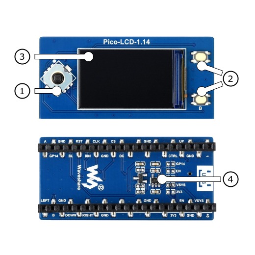
Operate with the LCD backlight LED LCD_BL at GP13:
uart:~$ regulator disable lcd-backlight-en
uart:~$ regulator enable lcd-backlight-en
Operate with the joystick button ENTER at GP3:
uart:~$ gpio get gpio@40014000 3
0

uart:~$ gpio conf gpio@40014000 3 iul
uart:~$ gpio get gpio@40014000 3
0
uart:~$ gpio get gpio@40014000 3
1
uart:~$ gpio get gpio@40014000 3
0
Using west:
west build -b rpi_pico/rp2040/w -p -S usb-console --shield "waveshare_pico_lcd_1_14" -d build/waveshare_pico_lcd_1_14-helloshell bridle/samples/helloshell
west flash -r uf2 -d build/waveshare_pico_lcd_1_14-helloshell
Using CMake and ninja:
# Use cmake to configure a Ninja-based buildsystem:
cmake -Bbuild/waveshare_pico_lcd_1_14-helloshell -GNinja -DBOARD=rpi_pico/rp2040/w -DSHIELD=""waveshare_pico_lcd_1_14"" bridle/samples/helloshell

# Now run the build tool on the generated build system:
ninja -Cbuild/waveshare_pico_lcd_1_14-helloshell flash
Simple test execution on target
(text in bold is a command input)
uart:~$ hello -h
hello - say hello
uart:~$ hello
Hello from shell.
uart:~$ hwinfo devid
Length: 8
ID: 0x8c998be1de969148

uart:~$ kernel version
Zephyr version 4.1.0

uart:~$ bridle version
Bridle version 4.1.0

uart:~$ bridle version long
Bridle version 4.1.0.0

uart:~$ bridle info
Zephyr: 4.1.0
Bridle: 4.1.0
uart:~$ device list
devices:
- clock-controller@40008000 (READY)
  DT node labels: clocks
- reset-controller@4000c000 (READY)
  DT node labels: reset
- snippet_cdc_acm_console_uart (READY)
  DT node labels: snippet_cdc_acm_console_uart
- uart@40034000 (READY)
  DT node labels: uart0 pico_serial rpipico_serial
- timer@40054000 (READY)
  DT node labels: timer
- gpio@40014000 (READY)
  DT node labels: gpio0
- adc@4004c000 (READY)
  DT node labels: adc
- flash-controller@18000000 (READY)
  DT node labels: ssi
- i2c@40044000 (READY)
  DT node labels: i2c0 pico_i2c pico_i2c0 rpipico_i2c rpipico_i2c0
- vreg@40064000 (READY)
  DT node labels: vreg
- rtc@4005c000 (READY)
  DT node labels: rtc
- lcd-backlight-en (READY)
  DT node labels: lcd_backlight_en
- leds (READY)
uart:~$ history
[  0] history
[  1] device list
[  2] bridle info
[  3] bridle version long
[  4] bridle version
[  5] kernel version
[  6] hwinfo devid
[  7] hello
[  8] hello -h
Operate with the LCD backlight LED LCD_BL at GP13:
uart:~$ regulator disable lcd-backlight-en
uart:~$ regulator enable lcd-backlight-en
Operate with the joystick button ENTER at GP3:
uart:~$ gpio get gpio@40014000 3
0

uart:~$ gpio conf gpio@40014000 3 iul
uart:~$ gpio get gpio@40014000 3
0
uart:~$ gpio get gpio@40014000 3
1
uart:~$ gpio get gpio@40014000 3
0
on standard 4㎆ revision
Using west:
west build -b waveshare_rp2040_plus -p -S usb-console --shield "waveshare_pico_lcd_1_14" -d build/waveshare_pico_lcd_1_14-helloshell bridle/samples/helloshell
west flash -r uf2 -d build/waveshare_pico_lcd_1_14-helloshell
Using CMake and ninja:
# Use cmake to configure a Ninja-based buildsystem:
cmake -Bbuild/waveshare_pico_lcd_1_14-helloshell -GNinja -DBOARD=waveshare_rp2040_plus -DSHIELD=""waveshare_pico_lcd_1_14"" bridle/samples/helloshell

# Now run the build tool on the generated build system:
ninja -Cbuild/waveshare_pico_lcd_1_14-helloshell flash
on extended 16㎆ revision
Using west:
west build -b waveshare_rp2040_plus@16mb -p -S usb-console --shield "waveshare_pico_lcd_1_14" -d build/waveshare_pico_lcd_1_14-helloshell bridle/samples/helloshell
west flash -r uf2 -d build/waveshare_pico_lcd_1_14-helloshell
Using CMake and ninja:
# Use cmake to configure a Ninja-based buildsystem:
cmake -Bbuild/waveshare_pico_lcd_1_14-helloshell -GNinja -DBOARD=waveshare_rp2040_plus@16mb -DSHIELD=""waveshare_pico_lcd_1_14"" bridle/samples/helloshell

# Now run the build tool on the generated build system:
ninja -Cbuild/waveshare_pico_lcd_1_14-helloshell flash
Simple test execution on target
(text in bold is a command input)
uart:~$ hello -h
hello - say hello
uart:~$ hello
Hello from shell.
uart:~$ hwinfo devid
Length: 8
ID: 0x8c998be1de969148

uart:~$ kernel version
Zephyr version 4.1.0

uart:~$ bridle version
Bridle version 4.1.0

uart:~$ bridle version long
Bridle version 4.1.0.0

uart:~$ bridle info
Zephyr: 4.1.0
Bridle: 4.1.0
uart:~$ device list
devices:
- clock-controller@40008000 (READY)
  DT node labels: clocks
- reset-controller@4000c000 (READY)
  DT node labels: reset
- snippet_cdc_acm_console_uart (READY)
  DT node labels: snippet_cdc_acm_console_uart
- uart@40034000 (READY)
  DT node labels: uart0 pico_serial rpipico_serial
- timer@40054000 (READY)
  DT node labels: timer
- gpio@40014000 (READY)
  DT node labels: gpio0
- adc@4004c000 (READY)
  DT node labels: adc
- flash-controller@18000000 (READY)
  DT node labels: ssi
- i2c@40044000 (READY)
  DT node labels: i2c0 pico_i2c pico_i2c0 rpipico_i2c rpipico_i2c0
- vreg@40064000 (READY)
  DT node labels: vreg
- rtc@4005c000 (READY)
  DT node labels: rtc
- lcd-backlight-en (READY)
  DT node labels: lcd_backlight_en
- leds (READY)
uart:~$ history
[  0] history
[  1] device list
[  2] bridle info
[  3] bridle version long
[  4] bridle version
[  5] kernel version
[  6] hwinfo devid
[  7] hello
[  8] hello -h
Operate with the LCD backlight LED LCD_BL at GP13:
uart:~$ regulator disable lcd-backlight-en
uart:~$ regulator enable lcd-backlight-en
Operate with the joystick button ENTER at GP3:
uart:~$ gpio get gpio@40014000 3
0

uart:~$ gpio conf gpio@40014000 3 iul
uart:~$ gpio get gpio@40014000 3
0
uart:~$ gpio get gpio@40014000 3
1
uart:~$ gpio get gpio@40014000 3
0
Set -DSHIELD=waveshare_pico_lcd_1_3 and use optional the
USB Console Snippet (usb-console) when you invoke west build.
For example:
Using west:
west build -b rpi_pico -p -S usb-console --shield "waveshare_pico_lcd_1_3" -d build/waveshare_pico_lcd_1_3-helloshell bridle/samples/helloshell
west flash -r uf2 -d build/waveshare_pico_lcd_1_3-helloshell
Using CMake and ninja:
# Use cmake to configure a Ninja-based buildsystem:
cmake -Bbuild/waveshare_pico_lcd_1_3-helloshell -GNinja -DBOARD=rpi_pico -DSHIELD=""waveshare_pico_lcd_1_3"" bridle/samples/helloshell

# Now run the build tool on the generated build system:
ninja -Cbuild/waveshare_pico_lcd_1_3-helloshell flash
Simple test execution on target
(text in bold is a command input)
uart:~$ hello -h
hello - say hello
uart:~$ hello
Hello from shell.
uart:~$ hwinfo devid
Length: 8
ID: 0x8c998be1de969148

uart:~$ kernel version
Zephyr version 4.1.0

uart:~$ bridle version
Bridle version 4.1.0

uart:~$ bridle version long
Bridle version 4.1.0.0

uart:~$ bridle info
Zephyr: 4.1.0
Bridle: 4.1.0
uart:~$ device list
devices:
- clock-controller@40008000 (READY)
  DT node labels: clocks
- reset-controller@4000c000 (READY)
  DT node labels: reset
- snippet_cdc_acm_console_uart (READY)
  DT node labels: snippet_cdc_acm_console_uart
- uart@40034000 (READY)
  DT node labels: uart0 pico_serial rpipico_serial
- timer@40054000 (READY)
  DT node labels: timer
- gpio@40014000 (READY)
  DT node labels: gpio0
- adc@4004c000 (READY)
  DT node labels: adc
- flash-controller@18000000 (READY)
  DT node labels: ssi
- i2c@40044000 (READY)
  DT node labels: i2c0 pico_i2c pico_i2c0 rpipico_i2c rpipico_i2c0
- vreg@40064000 (READY)
  DT node labels: vreg
- rtc@4005c000 (READY)
  DT node labels: rtc
- lcd-backlight-en (READY)
  DT node labels: lcd_backlight_en
- leds (READY)
uart:~$ history
[  0] history
[  1] device list
[  2] bridle info
[  3] bridle version long
[  4] bridle version
[  5] kernel version
[  6] hwinfo devid
[  7] hello
[  8] hello -h
Operate with the LCD backlight LED LCD_BL at GP13:
uart:~$ regulator disable lcd-backlight-en
uart:~$ regulator enable lcd-backlight-en
Operate with the joystick button ENTER at GP3:
uart:~$ gpio get gpio@40014000 3
0

uart:~$ gpio conf gpio@40014000 3 iul
uart:~$ gpio get gpio@40014000 3
0
uart:~$ gpio get gpio@40014000 3
1
uart:~$ gpio get gpio@40014000 3
0
Using west:
west build -b rpi_pico/rp2040/w -p -S usb-console --shield "waveshare_pico_lcd_1_3" -d build/waveshare_pico_lcd_1_3-helloshell bridle/samples/helloshell
west flash -r uf2 -d build/waveshare_pico_lcd_1_3-helloshell
Using CMake and ninja:
# Use cmake to configure a Ninja-based buildsystem:
cmake -Bbuild/waveshare_pico_lcd_1_3-helloshell -GNinja -DBOARD=rpi_pico/rp2040/w -DSHIELD=""waveshare_pico_lcd_1_3"" bridle/samples/helloshell

# Now run the build tool on the generated build system:
ninja -Cbuild/waveshare_pico_lcd_1_3-helloshell flash
Simple test execution on target
(text in bold is a command input)
uart:~$ hello -h
hello - say hello
uart:~$ hello
Hello from shell.
uart:~$ hwinfo devid
Length: 8
ID: 0x8c998be1de969148

uart:~$ kernel version
Zephyr version 4.1.0

uart:~$ bridle version
Bridle version 4.1.0

uart:~$ bridle version long
Bridle version 4.1.0.0

uart:~$ bridle info
Zephyr: 4.1.0
Bridle: 4.1.0
uart:~$ device list
devices:
- clock-controller@40008000 (READY)
  DT node labels: clocks
- reset-controller@4000c000 (READY)
  DT node labels: reset
- snippet_cdc_acm_console_uart (READY)
  DT node labels: snippet_cdc_acm_console_uart
- uart@40034000 (READY)
  DT node labels: uart0 pico_serial rpipico_serial
- timer@40054000 (READY)
  DT node labels: timer
- gpio@40014000 (READY)
  DT node labels: gpio0
- adc@4004c000 (READY)
  DT node labels: adc
- flash-controller@18000000 (READY)
  DT node labels: ssi
- i2c@40044000 (READY)
  DT node labels: i2c0 pico_i2c pico_i2c0 rpipico_i2c rpipico_i2c0
- vreg@40064000 (READY)
  DT node labels: vreg
- rtc@4005c000 (READY)
  DT node labels: rtc
- lcd-backlight-en (READY)
  DT node labels: lcd_backlight_en
- leds (READY)
uart:~$ history
[  0] history
[  1] device list
[  2] bridle info
[  3] bridle version long
[  4] bridle version
[  5] kernel version
[  6] hwinfo devid
[  7] hello
[  8] hello -h
Operate with the LCD backlight LED LCD_BL at GP13:
uart:~$ regulator disable lcd-backlight-en
uart:~$ regulator enable lcd-backlight-en
Operate with the joystick button ENTER at GP3:
uart:~$ gpio get gpio@40014000 3
0

uart:~$ gpio conf gpio@40014000 3 iul
uart:~$ gpio get gpio@40014000 3
0
uart:~$ gpio get gpio@40014000 3
1
uart:~$ gpio get gpio@40014000 3
0
on standard 4㎆ revision
Using west:
west build -b waveshare_rp2040_plus -p -S usb-console --shield "waveshare_pico_lcd_1_3" -d build/waveshare_pico_lcd_1_3-helloshell bridle/samples/helloshell
west flash -r uf2 -d build/waveshare_pico_lcd_1_3-helloshell
Using CMake and ninja:
# Use cmake to configure a Ninja-based buildsystem:
cmake -Bbuild/waveshare_pico_lcd_1_3-helloshell -GNinja -DBOARD=waveshare_rp2040_plus -DSHIELD=""waveshare_pico_lcd_1_3"" bridle/samples/helloshell

# Now run the build tool on the generated build system:
ninja -Cbuild/waveshare_pico_lcd_1_3-helloshell flash
on extended 16㎆ revision
Using west:
west build -b waveshare_rp2040_plus@16mb -p -S usb-console --shield "waveshare_pico_lcd_1_3" -d build/waveshare_pico_lcd_1_3-helloshell bridle/samples/helloshell
west flash -r uf2 -d build/waveshare_pico_lcd_1_3-helloshell
Using CMake and ninja:
# Use cmake to configure a Ninja-based buildsystem:
cmake -Bbuild/waveshare_pico_lcd_1_3-helloshell -GNinja -DBOARD=waveshare_rp2040_plus@16mb -DSHIELD=""waveshare_pico_lcd_1_3"" bridle/samples/helloshell

# Now run the build tool on the generated build system:
ninja -Cbuild/waveshare_pico_lcd_1_3-helloshell flash
Simple test execution on target
(text in bold is a command input)
uart:~$ hello -h
hello - say hello
uart:~$ hello
Hello from shell.
uart:~$ hwinfo devid
Length: 8
ID: 0x8c998be1de969148

uart:~$ kernel version
Zephyr version 4.1.0

uart:~$ bridle version
Bridle version 4.1.0

uart:~$ bridle version long
Bridle version 4.1.0.0

uart:~$ bridle info
Zephyr: 4.1.0
Bridle: 4.1.0
uart:~$ device list
devices:
- clock-controller@40008000 (READY)
  DT node labels: clocks
- reset-controller@4000c000 (READY)
  DT node labels: reset
- snippet_cdc_acm_console_uart (READY)
  DT node labels: snippet_cdc_acm_console_uart
- uart@40034000 (READY)
  DT node labels: uart0 pico_serial rpipico_serial
- timer@40054000 (READY)
  DT node labels: timer
- gpio@40014000 (READY)
  DT node labels: gpio0
- adc@4004c000 (READY)
  DT node labels: adc
- flash-controller@18000000 (READY)
  DT node labels: ssi
- i2c@40044000 (READY)
  DT node labels: i2c0 pico_i2c pico_i2c0 rpipico_i2c rpipico_i2c0
- vreg@40064000 (READY)
  DT node labels: vreg
- rtc@4005c000 (READY)
  DT node labels: rtc
- lcd-backlight-en (READY)
  DT node labels: lcd_backlight_en
- leds (READY)
uart:~$ history
[  0] history
[  1] device list
[  2] bridle info
[  3] bridle version long
[  4] bridle version
[  5] kernel version
[  6] hwinfo devid
[  7] hello
[  8] hello -h
Operate with the LCD backlight LED LCD_BL at GP13:
uart:~$ regulator disable lcd-backlight-en
uart:~$ regulator enable lcd-backlight-en
Operate with the joystick button ENTER at GP3:
uart:~$ gpio get gpio@40014000 3
0

uart:~$ gpio conf gpio@40014000 3 iul
uart:~$ gpio get gpio@40014000 3
0
uart:~$ gpio get gpio@40014000 3
1
uart:~$ gpio get gpio@40014000 3
0
Set -DSHIELD=waveshare_pico_lcd_1_44 and use optional the
USB Console Snippet (usb-console) when you invoke west build.
For example:
Using west:
west build -b rpi_pico -p -S usb-console --shield "waveshare_pico_lcd_1_44" -d build/waveshare_pico_lcd_1_44-helloshell bridle/samples/helloshell
west flash -r uf2 -d build/waveshare_pico_lcd_1_44-helloshell
Using CMake and ninja:
# Use cmake to configure a Ninja-based buildsystem:
cmake -Bbuild/waveshare_pico_lcd_1_44-helloshell -GNinja -DBOARD=rpi_pico -DSHIELD=""waveshare_pico_lcd_1_44"" bridle/samples/helloshell

# Now run the build tool on the generated build system:
ninja -Cbuild/waveshare_pico_lcd_1_44-helloshell flash
Simple test execution on target
(text in bold is a command input)
uart:~$ hello -h
hello - say hello
uart:~$ hello
Hello from shell.
uart:~$ hwinfo devid
Length: 8
ID: 0x8c998be1de969148

uart:~$ kernel version
Zephyr version 4.1.0

uart:~$ bridle version
Bridle version 4.1.0

uart:~$ bridle version long
Bridle version 4.1.0.0

uart:~$ bridle info
Zephyr: 4.1.0
Bridle: 4.1.0
uart:~$ device list
devices:
- clock-controller@40008000 (READY)
  DT node labels: clocks
- reset-controller@4000c000 (READY)
  DT node labels: reset
- snippet_cdc_acm_console_uart (READY)
  DT node labels: snippet_cdc_acm_console_uart
- uart@40034000 (READY)
  DT node labels: uart0 pico_serial rpipico_serial
- timer@40054000 (READY)
  DT node labels: timer
- gpio@40014000 (READY)
  DT node labels: gpio0
- adc@4004c000 (READY)
  DT node labels: adc
- flash-controller@18000000 (READY)
  DT node labels: ssi
- i2c@40044000 (READY)
  DT node labels: i2c0 pico_i2c pico_i2c0 rpipico_i2c rpipico_i2c0
- vreg@40064000 (READY)
  DT node labels: vreg
- rtc@4005c000 (READY)
  DT node labels: rtc
- lcd-backlight-en (READY)
  DT node labels: lcd_backlight_en
- leds (READY)
uart:~$ history
[  0] history
[  1] device list
[  2] bridle info
[  3] bridle version long
[  4] bridle version
[  5] kernel version
[  6] hwinfo devid
[  7] hello
[  8] hello -h
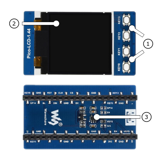
Operate with the LCD backlight LED LCD_BL at GP13:
uart:~$ regulator disable lcd-backlight-en
uart:~$ regulator enable lcd-backlight-en
Operate with the user button 3 at GP3:
uart:~$ gpio get gpio@40014000 3
0

uart:~$ gpio conf gpio@40014000 3 iul
uart:~$ gpio get gpio@40014000 3
0
uart:~$ gpio get gpio@40014000 3
1
uart:~$ gpio get gpio@40014000 3
0
Using west:
west build -b rpi_pico/rp2040/w -p -S usb-console --shield "waveshare_pico_lcd_1_44" -d build/waveshare_pico_lcd_1_44-helloshell bridle/samples/helloshell
west flash -r uf2 -d build/waveshare_pico_lcd_1_44-helloshell
Using CMake and ninja:
# Use cmake to configure a Ninja-based buildsystem:
cmake -Bbuild/waveshare_pico_lcd_1_44-helloshell -GNinja -DBOARD=rpi_pico/rp2040/w -DSHIELD=""waveshare_pico_lcd_1_44"" bridle/samples/helloshell

# Now run the build tool on the generated build system:
ninja -Cbuild/waveshare_pico_lcd_1_44-helloshell flash
Simple test execution on target
(text in bold is a command input)
uart:~$ hello -h
hello - say hello
uart:~$ hello
Hello from shell.
uart:~$ hwinfo devid
Length: 8
ID: 0x8c998be1de969148

uart:~$ kernel version
Zephyr version 4.1.0

uart:~$ bridle version
Bridle version 4.1.0

uart:~$ bridle version long
Bridle version 4.1.0.0

uart:~$ bridle info
Zephyr: 4.1.0
Bridle: 4.1.0
uart:~$ device list
devices:
- clock-controller@40008000 (READY)
  DT node labels: clocks
- reset-controller@4000c000 (READY)
  DT node labels: reset
- snippet_cdc_acm_console_uart (READY)
  DT node labels: snippet_cdc_acm_console_uart
- uart@40034000 (READY)
  DT node labels: uart0 pico_serial rpipico_serial
- timer@40054000 (READY)
  DT node labels: timer
- gpio@40014000 (READY)
  DT node labels: gpio0
- adc@4004c000 (READY)
  DT node labels: adc
- flash-controller@18000000 (READY)
  DT node labels: ssi
- i2c@40044000 (READY)
  DT node labels: i2c0 pico_i2c pico_i2c0 rpipico_i2c rpipico_i2c0
- vreg@40064000 (READY)
  DT node labels: vreg
- rtc@4005c000 (READY)
  DT node labels: rtc
- lcd-backlight-en (READY)
  DT node labels: lcd_backlight_en
- leds (READY)
uart:~$ history
[  0] history
[  1] device list
[  2] bridle info
[  3] bridle version long
[  4] bridle version
[  5] kernel version
[  6] hwinfo devid
[  7] hello
[  8] hello -h
Operate with the LCD backlight LED LCD_BL at GP13:
uart:~$ regulator disable lcd-backlight-en
uart:~$ regulator enable lcd-backlight-en
Operate with the user button 3 at GP3:
uart:~$ gpio get gpio@40014000 3
0

uart:~$ gpio conf gpio@40014000 3 iul
uart:~$ gpio get gpio@40014000 3
0
uart:~$ gpio get gpio@40014000 3
1
uart:~$ gpio get gpio@40014000 3
0
on standard 4㎆ revision
Using west:
west build -b waveshare_rp2040_plus -p -S usb-console --shield "waveshare_pico_lcd_1_44" -d build/waveshare_pico_lcd_1_44-helloshell bridle/samples/helloshell
west flash -r uf2 -d build/waveshare_pico_lcd_1_44-helloshell
Using CMake and ninja:
# Use cmake to configure a Ninja-based buildsystem:
cmake -Bbuild/waveshare_pico_lcd_1_44-helloshell -GNinja -DBOARD=waveshare_rp2040_plus -DSHIELD=""waveshare_pico_lcd_1_44"" bridle/samples/helloshell

# Now run the build tool on the generated build system:
ninja -Cbuild/waveshare_pico_lcd_1_44-helloshell flash
on extended 16㎆ revision
Using west:
west build -b waveshare_rp2040_plus@16mb -p -S usb-console --shield "waveshare_pico_lcd_1_44" -d build/waveshare_pico_lcd_1_44-helloshell bridle/samples/helloshell
west flash -r uf2 -d build/waveshare_pico_lcd_1_44-helloshell
Using CMake and ninja:
# Use cmake to configure a Ninja-based buildsystem:
cmake -Bbuild/waveshare_pico_lcd_1_44-helloshell -GNinja -DBOARD=waveshare_rp2040_plus@16mb -DSHIELD=""waveshare_pico_lcd_1_44"" bridle/samples/helloshell

# Now run the build tool on the generated build system:
ninja -Cbuild/waveshare_pico_lcd_1_44-helloshell flash
Simple test execution on target
(text in bold is a command input)
uart:~$ hello -h
hello - say hello
uart:~$ hello
Hello from shell.
uart:~$ hwinfo devid
Length: 8
ID: 0x8c998be1de969148

uart:~$ kernel version
Zephyr version 4.1.0

uart:~$ bridle version
Bridle version 4.1.0

uart:~$ bridle version long
Bridle version 4.1.0.0

uart:~$ bridle info
Zephyr: 4.1.0
Bridle: 4.1.0
uart:~$ device list
devices:
- clock-controller@40008000 (READY)
  DT node labels: clocks
- reset-controller@4000c000 (READY)
  DT node labels: reset
- snippet_cdc_acm_console_uart (READY)
  DT node labels: snippet_cdc_acm_console_uart
- uart@40034000 (READY)
  DT node labels: uart0 pico_serial rpipico_serial
- timer@40054000 (READY)
  DT node labels: timer
- gpio@40014000 (READY)
  DT node labels: gpio0
- adc@4004c000 (READY)
  DT node labels: adc
- flash-controller@18000000 (READY)
  DT node labels: ssi
- i2c@40044000 (READY)
  DT node labels: i2c0 pico_i2c pico_i2c0 rpipico_i2c rpipico_i2c0
- vreg@40064000 (READY)
  DT node labels: vreg
- rtc@4005c000 (READY)
  DT node labels: rtc
- lcd-backlight-en (READY)
  DT node labels: lcd_backlight_en
- leds (READY)
uart:~$ history
[  0] history
[  1] device list
[  2] bridle info
[  3] bridle version long
[  4] bridle version
[  5] kernel version
[  6] hwinfo devid
[  7] hello
[  8] hello -h
Operate with the LCD backlight LED LCD_BL at GP13:
uart:~$ regulator disable lcd-backlight-en
uart:~$ regulator enable lcd-backlight-en
Operate with the user button 3 at GP3:
uart:~$ gpio get gpio@40014000 3
0

uart:~$ gpio conf gpio@40014000 3 iul
uart:~$ gpio get gpio@40014000 3
0
uart:~$ gpio get gpio@40014000 3
1
uart:~$ gpio get gpio@40014000 3
0
Set -DSHIELD=waveshare_pico_lcd_1_8 and use optional the
USB Console Snippet (usb-console) when you invoke west build.
For example:
Using west:
west build -b rpi_pico -p -S usb-console --shield "waveshare_pico_lcd_1_8" -d build/waveshare_pico_lcd_1_8-helloshell bridle/samples/helloshell
west flash -r uf2 -d build/waveshare_pico_lcd_1_8-helloshell
Using CMake and ninja:
# Use cmake to configure a Ninja-based buildsystem:
cmake -Bbuild/waveshare_pico_lcd_1_8-helloshell -GNinja -DBOARD=rpi_pico -DSHIELD=""waveshare_pico_lcd_1_8"" bridle/samples/helloshell

# Now run the build tool on the generated build system:
ninja -Cbuild/waveshare_pico_lcd_1_8-helloshell flash
Simple test execution on target
(text in bold is a command input)
uart:~$ hello -h
hello - say hello
uart:~$ hello
Hello from shell.
uart:~$ hwinfo devid
Length: 8
ID: 0x8c998be1de969148

uart:~$ kernel version
Zephyr version 4.1.0

uart:~$ bridle version
Bridle version 4.1.0

uart:~$ bridle version long
Bridle version 4.1.0.0

uart:~$ bridle info
Zephyr: 4.1.0
Bridle: 4.1.0
uart:~$ device list
devices:
- clock-controller@40008000 (READY)
  DT node labels: clocks
- reset-controller@4000c000 (READY)
  DT node labels: reset
- snippet_cdc_acm_console_uart (READY)
  DT node labels: snippet_cdc_acm_console_uart
- uart@40034000 (READY)
  DT node labels: uart0 pico_serial rpipico_serial
- timer@40054000 (READY)
  DT node labels: timer
- gpio@40014000 (READY)
  DT node labels: gpio0
- adc@4004c000 (READY)
  DT node labels: adc
- flash-controller@18000000 (READY)
  DT node labels: ssi
- i2c@40044000 (READY)
  DT node labels: i2c0 pico_i2c pico_i2c0 rpipico_i2c rpipico_i2c0
- vreg@40064000 (READY)
  DT node labels: vreg
- rtc@4005c000 (READY)
  DT node labels: rtc
- lcd-backlight-en (READY)
  DT node labels: lcd_backlight_en
- leds (READY)
uart:~$ history
[  0] history
[  1] device list
[  2] bridle info
[  3] bridle version long
[  4] bridle version
[  5] kernel version
[  6] hwinfo devid
[  7] hello
[  8] hello -h
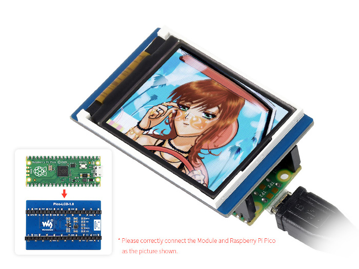
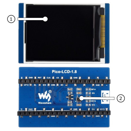
Operate with the LCD backlight LED LCD_BL at GP13:
uart:~$ regulator disable lcd-backlight-en
uart:~$ regulator enable lcd-backlight-en
Using west:
west build -b rpi_pico/rp2040/w -p -S usb-console --shield "waveshare_pico_lcd_1_8" -d build/waveshare_pico_lcd_1_8-helloshell bridle/samples/helloshell
west flash -r uf2 -d build/waveshare_pico_lcd_1_8-helloshell
Using CMake and ninja:
# Use cmake to configure a Ninja-based buildsystem:
cmake -Bbuild/waveshare_pico_lcd_1_8-helloshell -GNinja -DBOARD=rpi_pico/rp2040/w -DSHIELD=""waveshare_pico_lcd_1_8"" bridle/samples/helloshell

# Now run the build tool on the generated build system:
ninja -Cbuild/waveshare_pico_lcd_1_8-helloshell flash
Simple test execution on target
(text in bold is a command input)
uart:~$ hello -h
hello - say hello
uart:~$ hello
Hello from shell.
uart:~$ hwinfo devid
Length: 8
ID: 0x8c998be1de969148

uart:~$ kernel version
Zephyr version 4.1.0

uart:~$ bridle version
Bridle version 4.1.0

uart:~$ bridle version long
Bridle version 4.1.0.0

uart:~$ bridle info
Zephyr: 4.1.0
Bridle: 4.1.0
uart:~$ device list
devices:
- clock-controller@40008000 (READY)
  DT node labels: clocks
- reset-controller@4000c000 (READY)
  DT node labels: reset
- snippet_cdc_acm_console_uart (READY)
  DT node labels: snippet_cdc_acm_console_uart
- uart@40034000 (READY)
  DT node labels: uart0 pico_serial rpipico_serial
- timer@40054000 (READY)
  DT node labels: timer
- gpio@40014000 (READY)
  DT node labels: gpio0
- adc@4004c000 (READY)
  DT node labels: adc
- flash-controller@18000000 (READY)
  DT node labels: ssi
- i2c@40044000 (READY)
  DT node labels: i2c0 pico_i2c pico_i2c0 rpipico_i2c rpipico_i2c0
- vreg@40064000 (READY)
  DT node labels: vreg
- rtc@4005c000 (READY)
  DT node labels: rtc
- lcd-backlight-en (READY)
  DT node labels: lcd_backlight_en
- leds (READY)
uart:~$ history
[  0] history
[  1] device list
[  2] bridle info
[  3] bridle version long
[  4] bridle version
[  5] kernel version
[  6] hwinfo devid
[  7] hello
[  8] hello -h
Operate with the LCD backlight LED LCD_BL at GP13:
uart:~$ regulator disable lcd-backlight-en
uart:~$ regulator enable lcd-backlight-en
on standard 4㎆ revision
Using west:
west build -b waveshare_rp2040_plus -p -S usb-console --shield "waveshare_pico_lcd_1_8" -d build/waveshare_pico_lcd_1_8-helloshell bridle/samples/helloshell
west flash -r uf2 -d build/waveshare_pico_lcd_1_8-helloshell
Using CMake and ninja:
# Use cmake to configure a Ninja-based buildsystem:
cmake -Bbuild/waveshare_pico_lcd_1_8-helloshell -GNinja -DBOARD=waveshare_rp2040_plus -DSHIELD=""waveshare_pico_lcd_1_8"" bridle/samples/helloshell

# Now run the build tool on the generated build system:
ninja -Cbuild/waveshare_pico_lcd_1_8-helloshell flash
on extended 16㎆ revision
Using west:
west build -b waveshare_rp2040_plus@16mb -p -S usb-console --shield "waveshare_pico_lcd_1_8" -d build/waveshare_pico_lcd_1_8-helloshell bridle/samples/helloshell
west flash -r uf2 -d build/waveshare_pico_lcd_1_8-helloshell
Using CMake and ninja:
# Use cmake to configure a Ninja-based buildsystem:
cmake -Bbuild/waveshare_pico_lcd_1_8-helloshell -GNinja -DBOARD=waveshare_rp2040_plus@16mb -DSHIELD=""waveshare_pico_lcd_1_8"" bridle/samples/helloshell

# Now run the build tool on the generated build system:
ninja -Cbuild/waveshare_pico_lcd_1_8-helloshell flash
Simple test execution on target
(text in bold is a command input)
uart:~$ hello -h
hello - say hello
uart:~$ hello
Hello from shell.
uart:~$ hwinfo devid
Length: 8
ID: 0x8c998be1de969148

uart:~$ kernel version
Zephyr version 4.1.0

uart:~$ bridle version
Bridle version 4.1.0

uart:~$ bridle version long
Bridle version 4.1.0.0

uart:~$ bridle info
Zephyr: 4.1.0
Bridle: 4.1.0
uart:~$ device list
devices:
- clock-controller@40008000 (READY)
  DT node labels: clocks
- reset-controller@4000c000 (READY)
  DT node labels: reset
- snippet_cdc_acm_console_uart (READY)
  DT node labels: snippet_cdc_acm_console_uart
- uart@40034000 (READY)
  DT node labels: uart0 pico_serial rpipico_serial
- timer@40054000 (READY)
  DT node labels: timer
- gpio@40014000 (READY)
  DT node labels: gpio0
- adc@4004c000 (READY)
  DT node labels: adc
- flash-controller@18000000 (READY)
  DT node labels: ssi
- i2c@40044000 (READY)
  DT node labels: i2c0 pico_i2c pico_i2c0 rpipico_i2c rpipico_i2c0
- vreg@40064000 (READY)
  DT node labels: vreg
- rtc@4005c000 (READY)
  DT node labels: rtc
- lcd-backlight-en (READY)
  DT node labels: lcd_backlight_en
- leds (READY)
uart:~$ history
[  0] history
[  1] device list
[  2] bridle info
[  3] bridle version long
[  4] bridle version
[  5] kernel version
[  6] hwinfo devid
[  7] hello
[  8] hello -h
Operate with the LCD backlight LED LCD_BL at GP13:
uart:~$ regulator disable lcd-backlight-en
uart:~$ regulator enable lcd-backlight-en
Set -DSHIELD=waveshare_pico_lcd_2 and use optional the
USB Console Snippet (usb-console) when you invoke west build.
For example:
Using west:
west build -b rpi_pico -p -S usb-console --shield "waveshare_pico_lcd_2" -d build/waveshare_pico_lcd_2-helloshell bridle/samples/helloshell
west flash -r uf2 -d build/waveshare_pico_lcd_2-helloshell
Using CMake and ninja:
# Use cmake to configure a Ninja-based buildsystem:
cmake -Bbuild/waveshare_pico_lcd_2-helloshell -GNinja -DBOARD=rpi_pico -DSHIELD=""waveshare_pico_lcd_2"" bridle/samples/helloshell

# Now run the build tool on the generated build system:
ninja -Cbuild/waveshare_pico_lcd_2-helloshell flash
Simple test execution on target
(text in bold is a command input)
uart:~$ hello -h
hello - say hello
uart:~$ hello
Hello from shell.
uart:~$ hwinfo devid
Length: 8
ID: 0x8c998be1de969148

uart:~$ kernel version
Zephyr version 4.1.0

uart:~$ bridle version
Bridle version 4.1.0

uart:~$ bridle version long
Bridle version 4.1.0.0

uart:~$ bridle info
Zephyr: 4.1.0
Bridle: 4.1.0
uart:~$ device list
devices:
- clock-controller@40008000 (READY)
  DT node labels: clocks
- reset-controller@4000c000 (READY)
  DT node labels: reset
- snippet_cdc_acm_console_uart (READY)
  DT node labels: snippet_cdc_acm_console_uart
- uart@40034000 (READY)
  DT node labels: uart0 pico_serial rpipico_serial
- timer@40054000 (READY)
  DT node labels: timer
- gpio@40014000 (READY)
  DT node labels: gpio0
- adc@4004c000 (READY)
  DT node labels: adc
- flash-controller@18000000 (READY)
  DT node labels: ssi
- i2c@40044000 (READY)
  DT node labels: i2c0 pico_i2c pico_i2c0 rpipico_i2c rpipico_i2c0
- vreg@40064000 (READY)
  DT node labels: vreg
- rtc@4005c000 (READY)
  DT node labels: rtc
- lcd-backlight-en (READY)
  DT node labels: lcd_backlight_en
- leds (READY)
uart:~$ history
[  0] history
[  1] device list
[  2] bridle info
[  3] bridle version long
[  4] bridle version
[  5] kernel version
[  6] hwinfo devid
[  7] hello
[  8] hello -h
Operate with the LCD backlight LED LCD_BL at GP13:
uart:~$ regulator disable lcd-backlight-en
uart:~$ regulator enable lcd-backlight-en
Operate with the user button 3 at GP3:
uart:~$ gpio get gpio@40014000 3
0

uart:~$ gpio conf gpio@40014000 3 iul
uart:~$ gpio get gpio@40014000 3
0
uart:~$ gpio get gpio@40014000 3
1
uart:~$ gpio get gpio@40014000 3
0
Using west:
west build -b rpi_pico/rp2040/w -p -S usb-console --shield "waveshare_pico_lcd_2" -d build/waveshare_pico_lcd_2-helloshell bridle/samples/helloshell
west flash -r uf2 -d build/waveshare_pico_lcd_2-helloshell
Using CMake and ninja:
# Use cmake to configure a Ninja-based buildsystem:
cmake -Bbuild/waveshare_pico_lcd_2-helloshell -GNinja -DBOARD=rpi_pico/rp2040/w -DSHIELD=""waveshare_pico_lcd_2"" bridle/samples/helloshell
# Now run the build tool on the generated build system:
ninja -Cbuild/waveshare_pico_lcd_2-helloshell flash
Simple test execution on target
(text in bold is a command input)
uart:~$ hello -h
hello - say hello
uart:~$ hello
Hello from shell.
uart:~$ hwinfo devid
Length: 8
ID: 0x8c998be1de969148
uart:~$ kernel version
Zephyr version 4.1.0
uart:~$ bridle version
Bridle version 4.1.0
uart:~$ bridle version long
Bridle version 4.1.0.0
uart:~$ bridle info
Zephyr: 4.1.0
Bridle: 4.1.0
uart:~$ device list
devices:
- clock-controller@40008000 (READY)
DT node labels: clocks
- reset-controller@4000c000 (READY)
DT node labels: reset
- snippet_cdc_acm_console_uart (READY)
DT node labels: snippet_cdc_acm_console_uart
- uart@40034000 (READY)
DT node labels: uart0 pico_serial rpipico_serial
- timer@40054000 (READY)
DT node labels: timer
- gpio@40014000 (READY)
DT node labels: gpio0
- adc@4004c000 (READY)
DT node labels: adc
- flash-controller@18000000 (READY)
DT node labels: ssi
- i2c@40044000 (READY)
DT node labels: i2c0 pico_i2c pico_i2c0 rpipico_i2c rpipico_i2c0
- vreg@40064000 (READY)
DT node labels: vreg
- rtc@4005c000 (READY)
DT node labels: rtc
- lcd-backlight-en (READY)
DT node labels: lcd_backlight_en
- leds (READY)
uart:~$ history
[ 0] history
[ 1] device list
[ 2] bridle info
[ 3] bridle version long
[ 4] bridle version
[ 5] kernel version
[ 6] hwinfo devid
[ 7] hello
[ 8] hello -h
Operate with the LCD backlight LED LCD_BL at GP13:
uart:~$ regulator disable lcd-backlight-en
uart:~$ regulator enable lcd-backlight-en
Operate with the user button 3 at GP3:
uart:~$ gpio get gpio@40014000 3
0
uart:~$ gpio conf gpio@40014000 3 iul
uart:~$ gpio get gpio@40014000 3
0
uart:~$ gpio get gpio@40014000 3
1
uart:~$ gpio get gpio@40014000 3
0
on standard 4㎆ revision
Using west:
west build -b waveshare_rp2040_plus -p -S usb-console --shield "waveshare_pico_lcd_2" -d build/waveshare_pico_lcd_2-helloshell bridle/samples/helloshell
west flash -r uf2 -d build/waveshare_pico_lcd_2-helloshell
Using CMake and ninja:
# Use cmake to configure a Ninja-based buildsystem:
cmake -Bbuild/waveshare_pico_lcd_2-helloshell -GNinja -DBOARD=waveshare_rp2040_plus -DSHIELD=""waveshare_pico_lcd_2"" bridle/samples/helloshell
# Now run the build tool on the generated build system:
ninja -Cbuild/waveshare_pico_lcd_2-helloshell flash
on extended 16㎆ revision
Using west:
west build -b waveshare_rp2040_plus@16mb -p -S usb-console --shield "waveshare_pico_lcd_2" -d build/waveshare_pico_lcd_2-helloshell bridle/samples/helloshell
west flash -r uf2 -d build/waveshare_pico_lcd_2-helloshell
Using CMake and ninja:
# Use cmake to configure a Ninja-based buildsystem:
cmake -Bbuild/waveshare_pico_lcd_2-helloshell -GNinja -DBOARD=waveshare_rp2040_plus@16mb -DSHIELD=""waveshare_pico_lcd_2"" bridle/samples/helloshell
# Now run the build tool on the generated build system:
ninja -Cbuild/waveshare_pico_lcd_2-helloshell flash
Simple test execution on target
(text in bold is a command input)
uart:~$ hello -h
hello - say hello
uart:~$ hello
Hello from shell.
uart:~$ hwinfo devid
Length: 8
ID: 0x8c998be1de969148
uart:~$ kernel version
Zephyr version 4.1.0
uart:~$ bridle version
Bridle version 4.1.0
uart:~$ bridle version long
Bridle version 4.1.0.0
uart:~$ bridle info
Zephyr: 4.1.0
Bridle: 4.1.0
uart:~$ device list
devices:
- clock-controller@40008000 (READY)
DT node labels: clocks
- reset-controller@4000c000 (READY)
DT node labels: reset
- snippet_cdc_acm_console_uart (READY)
DT node labels: snippet_cdc_acm_console_uart
- uart@40034000 (READY)
DT node labels: uart0 pico_serial rpipico_serial
- timer@40054000 (READY)
DT node labels: timer
- gpio@40014000 (READY)
DT node labels: gpio0
- adc@4004c000 (READY)
DT node labels: adc
- flash-controller@18000000 (READY)
DT node labels: ssi
- i2c@40044000 (READY)
DT node labels: i2c0 pico_i2c pico_i2c0 rpipico_i2c rpipico_i2c0
- vreg@40064000 (READY)
DT node labels: vreg
- rtc@4005c000 (READY)
DT node labels: rtc
- lcd-backlight-en (READY)
DT node labels: lcd_backlight_en
- leds (READY)
uart:~$ history
[ 0] history
[ 1] device list
[ 2] bridle info
[ 3] bridle version long
[ 4] bridle version
[ 5] kernel version
[ 6] hwinfo devid
[ 7] hello
[ 8] hello -h
Operate with the LCD backlight LED LCD_BL at GP13:
uart:~$ regulator disable lcd-backlight-en
uart:~$ regulator enable lcd-backlight-en
Operate with the user button 3 at GP3:
uart:~$ gpio get gpio@40014000 3
0
uart:~$ gpio conf gpio@40014000 3 iul
uart:~$ gpio get gpio@40014000 3
0
uart:~$ gpio get gpio@40014000 3
1
uart:~$ gpio get gpio@40014000 3
0
Set -DSHIELD=waveshare_pico_restouch_lcd_2_8 and use optional the
USB Console Snippet (usb-console) when you invoke west build.
For example:
Using west:
west build -b rpi_pico -p -S usb-console --shield "waveshare_pico_restouch_lcd_2_8" -d build/waveshare_pico_restouch_lcd_2_8-helloshell bridle/samples/helloshell
west flash -r uf2 -d build/waveshare_pico_restouch_lcd_2_8-helloshell
Using CMake and ninja:
# Use cmake to configure a Ninja-based buildsystem:
cmake -Bbuild/waveshare_pico_restouch_lcd_2_8-helloshell -GNinja -DBOARD=rpi_pico -DSHIELD=""waveshare_pico_restouch_lcd_2_8"" bridle/samples/helloshell
# Now run the build tool on the generated build system:
ninja -Cbuild/waveshare_pico_restouch_lcd_2_8-helloshell flash
Simple test execution on target
(text in bold is a command input)
uart:~$ hello -h
hello - say hello
uart:~$ hello
Hello from shell.
uart:~$ hwinfo devid
Length: 8
ID: 0x8c998be1de969148
uart:~$ kernel version
Zephyr version 4.1.0
uart:~$ bridle version
Bridle version 4.1.0
uart:~$ bridle version long
Bridle version 4.1.0.0
uart:~$ bridle info
Zephyr: 4.1.0
Bridle: 4.1.0
uart:~$ device list
devices:
- clock-controller@40008000 (READY)
DT node labels: clocks
- reset-controller@4000c000 (READY)
DT node labels: reset
- snippet_cdc_acm_console_uart (READY)
DT node labels: snippet_cdc_acm_console_uart
- uart@40034000 (READY)
DT node labels: uart0 pico_serial rpipico_serial
- timer@40054000 (READY)
DT node labels: timer
- gpio@40014000 (READY)
DT node labels: gpio0
- adc@4004c000 (READY)
DT node labels: adc
- flash-controller@18000000 (READY)
DT node labels: ssi
- i2c@40044000 (READY)
DT node labels: i2c0 pico_i2c pico_i2c0 rpipico_i2c rpipico_i2c0
- vreg@40064000 (READY)
DT node labels: vreg
- rtc@4005c000 (READY)
DT node labels: rtc
- lcd-backlight-en (READY)
DT node labels: lcd_backlight_en
- leds (READY)
uart:~$ history
[ 0] history
[ 1] device list
[ 2] bridle info
[ 3] bridle version long
[ 4] bridle version
[ 5] kernel version
[ 6] hwinfo devid
[ 7] hello
[ 8] hello -h
Operate with the LCD backlight LED LCD_BL at GP13:
uart:~$ regulator disable lcd-backlight-en
uart:~$ regulator enable lcd-backlight-en
Using west:
west build -b rpi_pico/rp2040/w -p -S usb-console --shield "waveshare_pico_restouch_lcd_2_8" -d build/waveshare_pico_restouch_lcd_2_8-helloshell bridle/samples/helloshell
west flash -r uf2 -d build/waveshare_pico_restouch_lcd_2_8-helloshell
Using CMake and ninja:
# Use cmake to configure a Ninja-based buildsystem:
cmake -Bbuild/waveshare_pico_restouch_lcd_2_8-helloshell -GNinja -DBOARD=rpi_pico/rp2040/w -DSHIELD=""waveshare_pico_restouch_lcd_2_8"" bridle/samples/helloshell
# Now run the build tool on the generated build system:
ninja -Cbuild/waveshare_pico_restouch_lcd_2_8-helloshell flash
Simple test execution on target
(text in bold is a command input)
uart:~$ hello -h
hello - say hello
uart:~$ hello
Hello from shell.
uart:~$ hwinfo devid
Length: 8
ID: 0x8c998be1de969148
uart:~$ kernel version
Zephyr version 4.1.0
uart:~$ bridle version
Bridle version 4.1.0
uart:~$ bridle version long
Bridle version 4.1.0.0
uart:~$ bridle info
Zephyr: 4.1.0
Bridle: 4.1.0
uart:~$ device list
devices:
- clock-controller@40008000 (READY)
DT node labels: clocks
- reset-controller@4000c000 (READY)
DT node labels: reset
- snippet_cdc_acm_console_uart (READY)
DT node labels: snippet_cdc_acm_console_uart
- uart@40034000 (READY)
DT node labels: uart0 pico_serial rpipico_serial
- timer@40054000 (READY)
DT node labels: timer
- gpio@40014000 (READY)
DT node labels: gpio0
- adc@4004c000 (READY)
DT node labels: adc
- flash-controller@18000000 (READY)
DT node labels: ssi
- i2c@40044000 (READY)
DT node labels: i2c0 pico_i2c pico_i2c0 rpipico_i2c rpipico_i2c0
- vreg@40064000 (READY)
DT node labels: vreg
- rtc@4005c000 (READY)
DT node labels: rtc
- lcd-backlight-en (READY)
DT node labels: lcd_backlight_en
- leds (READY)
uart:~$ history
[ 0] history
[ 1] device list
[ 2] bridle info
[ 3] bridle version long
[ 4] bridle version
[ 5] kernel version
[ 6] hwinfo devid
[ 7] hello
[ 8] hello -h
Operate with the LCD backlight LED LCD_BL at GP13:
uart:~$ regulator disable lcd-backlight-en
uart:~$ regulator enable lcd-backlight-en
on standard 4㎆ revision
Using west:
west build -b waveshare_rp2040_plus -p -S usb-console --shield "waveshare_pico_restouch_lcd_2_8" -d build/waveshare_pico_restouch_lcd_2_8-helloshell bridle/samples/helloshell
west flash -r uf2 -d build/waveshare_pico_restouch_lcd_2_8-helloshell
Using CMake and ninja:
# Use cmake to configure a Ninja-based buildsystem:
cmake -Bbuild/waveshare_pico_restouch_lcd_2_8-helloshell -GNinja -DBOARD=waveshare_rp2040_plus -DSHIELD=""waveshare_pico_restouch_lcd_2_8"" bridle/samples/helloshell
# Now run the build tool on the generated build system:
ninja -Cbuild/waveshare_pico_restouch_lcd_2_8-helloshell flash
on extended 16㎆ revision
Using west:
west build -b waveshare_rp2040_plus@16mb -p -S usb-console --shield "waveshare_pico_restouch_lcd_2_8" -d build/waveshare_pico_restouch_lcd_2_8-helloshell bridle/samples/helloshell
west flash -r uf2 -d build/waveshare_pico_restouch_lcd_2_8-helloshell
Using CMake and ninja:
# Use cmake to configure a Ninja-based buildsystem:
cmake -Bbuild/waveshare_pico_restouch_lcd_2_8-helloshell -GNinja -DBOARD=waveshare_rp2040_plus@16mb -DSHIELD=""waveshare_pico_restouch_lcd_2_8"" bridle/samples/helloshell
# Now run the build tool on the generated build system:
ninja -Cbuild/waveshare_pico_restouch_lcd_2_8-helloshell flash
Simple test execution on target
(text in bold is a command input)
uart:~$ hello -h
hello - say hello
uart:~$ hello
Hello from shell.
uart:~$ hwinfo devid
Length: 8
ID: 0x8c998be1de969148
uart:~$ kernel version
Zephyr version 4.1.0
uart:~$ bridle version
Bridle version 4.1.0
uart:~$ bridle version long
Bridle version 4.1.0.0
uart:~$ bridle info
Zephyr: 4.1.0
Bridle: 4.1.0
uart:~$ device list
devices:
- clock-controller@40008000 (READY)
DT node labels: clocks
- reset-controller@4000c000 (READY)
DT node labels: reset
- snippet_cdc_acm_console_uart (READY)
DT node labels: snippet_cdc_acm_console_uart
- uart@40034000 (READY)
DT node labels: uart0 pico_serial rpipico_serial
- timer@40054000 (READY)
DT node labels: timer
- gpio@40014000 (READY)
DT node labels: gpio0
- adc@4004c000 (READY)
DT node labels: adc
- flash-controller@18000000 (READY)
DT node labels: ssi
- i2c@40044000 (READY)
DT node labels: i2c0 pico_i2c pico_i2c0 rpipico_i2c rpipico_i2c0
- vreg@40064000 (READY)
DT node labels: vreg
- rtc@4005c000 (READY)
DT node labels: rtc
- lcd-backlight-en (READY)
DT node labels: lcd_backlight_en
- leds (READY)
uart:~$ history
[ 0] history
[ 1] device list
[ 2] bridle info
[ 3] bridle version long
[ 4] bridle version
[ 5] kernel version
[ 6] hwinfo devid
[ 7] hello
[ 8] hello -h
Operate with the LCD backlight LED LCD_BL at GP13:
uart:~$ regulator disable lcd-backlight-en
uart:~$ regulator enable lcd-backlight-en
Set -DSHIELD=waveshare_pico_restouch_lcd_3_5 and use optional the
USB Console Snippet (usb-console) when you invoke west build.
For example:
Using west:
west build -b rpi_pico -p -S usb-console --shield "waveshare_pico_restouch_lcd_3_5" -d build/waveshare_pico_restouch_lcd_3_5-helloshell bridle/samples/helloshell
west flash -r uf2 -d build/waveshare_pico_restouch_lcd_3_5-helloshell
Using CMake and ninja:
# Use cmake to configure a Ninja-based buildsystem:
cmake -Bbuild/waveshare_pico_restouch_lcd_3_5-helloshell -GNinja -DBOARD=rpi_pico -DSHIELD=""waveshare_pico_restouch_lcd_3_5"" bridle/samples/helloshell
# Now run the build tool on the generated build system:
ninja -Cbuild/waveshare_pico_restouch_lcd_3_5-helloshell flash
Simple test execution on target
(text in bold is a command input)
uart:~$ hello -h
hello - say hello
uart:~$ hello
Hello from shell.
uart:~$ hwinfo devid
Length: 8
ID: 0x8c998be1de969148
uart:~$ kernel version
Zephyr version 4.1.0
uart:~$ bridle version
Bridle version 4.1.0
uart:~$ bridle version long
Bridle version 4.1.0.0
uart:~$ bridle info
Zephyr: 4.1.0
Bridle: 4.1.0
uart:~$ device list
devices:
- clock-controller@40008000 (READY)
DT node labels: clocks
- reset-controller@4000c000 (READY)
DT node labels: reset
- snippet_cdc_acm_console_uart (READY)
DT node labels: snippet_cdc_acm_console_uart
- uart@40034000 (READY)
DT node labels: uart0 pico_serial rpipico_serial
- timer@40054000 (READY)
DT node labels: timer
- gpio@40014000 (READY)
DT node labels: gpio0
- adc@4004c000 (READY)
DT node labels: adc
- flash-controller@18000000 (READY)
DT node labels: ssi
- i2c@40044000 (READY)
DT node labels: i2c0 pico_i2c pico_i2c0 rpipico_i2c rpipico_i2c0
- vreg@40064000 (READY)
DT node labels: vreg
- rtc@4005c000 (READY)
DT node labels: rtc
- lcd-backlight-en (READY)
DT node labels: lcd_backlight_en
- leds (READY)
uart:~$ history
[ 0] history
[ 1] device list
[ 2] bridle info
[ 3] bridle version long
[ 4] bridle version
[ 5] kernel version
[ 6] hwinfo devid
[ 7] hello
[ 8] hello -h
Operate with the LCD backlight LED LCD_BL at GP13:
uart:~$ regulator disable lcd-backlight-en
uart:~$ regulator enable lcd-backlight-en
Using west:
west build -b rpi_pico/rp2040/w -p -S usb-console --shield "waveshare_pico_restouch_lcd_3_5" -d build/waveshare_pico_restouch_lcd_3_5-helloshell bridle/samples/helloshell
west flash -r uf2 -d build/waveshare_pico_restouch_lcd_3_5-helloshell
Using CMake and ninja:
# Use cmake to configure a Ninja-based buildsystem:
cmake -Bbuild/waveshare_pico_restouch_lcd_3_5-helloshell -GNinja -DBOARD=rpi_pico/rp2040/w -DSHIELD=""waveshare_pico_restouch_lcd_3_5"" bridle/samples/helloshell
# Now run the build tool on the generated build system:
ninja -Cbuild/waveshare_pico_restouch_lcd_3_5-helloshell flash
Simple test execution on target
(text in bold is a command input)
uart:~$ hello -h
hello - say hello
uart:~$ hello
Hello from shell.
uart:~$ hwinfo devid
Length: 8
ID: 0x8c998be1de969148
uart:~$ kernel version
Zephyr version 4.1.0
uart:~$ bridle version
Bridle version 4.1.0
uart:~$ bridle version long
Bridle version 4.1.0.0
uart:~$ bridle info
Zephyr: 4.1.0
Bridle: 4.1.0
uart:~$ device list
devices:
- clock-controller@40008000 (READY)
DT node labels: clocks
- reset-controller@4000c000 (READY)
DT node labels: reset
- snippet_cdc_acm_console_uart (READY)
DT node labels: snippet_cdc_acm_console_uart
- uart@40034000 (READY)
DT node labels: uart0 pico_serial rpipico_serial
- timer@40054000 (READY)
DT node labels: timer
- gpio@40014000 (READY)
DT node labels: gpio0
- adc@4004c000 (READY)
DT node labels: adc
- flash-controller@18000000 (READY)
DT node labels: ssi
- i2c@40044000 (READY)
DT node labels: i2c0 pico_i2c pico_i2c0 rpipico_i2c rpipico_i2c0
- vreg@40064000 (READY)
DT node labels: vreg
- rtc@4005c000 (READY)
DT node labels: rtc
- lcd-backlight-en (READY)
DT node labels: lcd_backlight_en
- leds (READY)
uart:~$ history
[ 0] history
[ 1] device list
[ 2] bridle info
[ 3] bridle version long
[ 4] bridle version
[ 5] kernel version
[ 6] hwinfo devid
[ 7] hello
[ 8] hello -h
Operate with the LCD backlight LED LCD_BL at GP13:
uart:~$ regulator disable lcd-backlight-en
uart:~$ regulator enable lcd-backlight-en
on standard 4㎆ revision
Using west:
west build -b waveshare_rp2040_plus -p -S usb-console --shield "waveshare_pico_restouch_lcd_3_5" -d build/waveshare_pico_restouch_lcd_3_5-helloshell bridle/samples/helloshell
west flash -r uf2 -d build/waveshare_pico_restouch_lcd_3_5-helloshell
Using CMake and ninja:
# Use cmake to configure a Ninja-based buildsystem:
cmake -Bbuild/waveshare_pico_restouch_lcd_3_5-helloshell -GNinja -DBOARD=waveshare_rp2040_plus -DSHIELD=""waveshare_pico_restouch_lcd_3_5"" bridle/samples/helloshell
# Now run the build tool on the generated build system:
ninja -Cbuild/waveshare_pico_restouch_lcd_3_5-helloshell flash
on extended 16㎆ revision
Using west:
west build -b waveshare_rp2040_plus@16mb -p -S usb-console --shield "waveshare_pico_restouch_lcd_3_5" -d build/waveshare_pico_restouch_lcd_3_5-helloshell bridle/samples/helloshell
west flash -r uf2 -d build/waveshare_pico_restouch_lcd_3_5-helloshell
Using CMake and ninja:
# Use cmake to configure a Ninja-based buildsystem:
cmake -Bbuild/waveshare_pico_restouch_lcd_3_5-helloshell -GNinja -DBOARD=waveshare_rp2040_plus@16mb -DSHIELD=""waveshare_pico_restouch_lcd_3_5"" bridle/samples/helloshell
# Now run the build tool on the generated build system:
ninja -Cbuild/waveshare_pico_restouch_lcd_3_5-helloshell flash
Simple test execution on target
(text in bold is a command input)
uart:~$ hello -h
hello - say hello
uart:~$ hello
Hello from shell.
uart:~$ hwinfo devid
Length: 8
ID: 0x8c998be1de969148
uart:~$ kernel version
Zephyr version 4.1.0
uart:~$ bridle version
Bridle version 4.1.0
uart:~$ bridle version long
Bridle version 4.1.0.0
uart:~$ bridle info
Zephyr: 4.1.0
Bridle: 4.1.0
uart:~$ device list
devices:
- clock-controller@40008000 (READY)
DT node labels: clocks
- reset-controller@4000c000 (READY)
DT node labels: reset
- snippet_cdc_acm_console_uart (READY)
DT node labels: snippet_cdc_acm_console_uart
- uart@40034000 (READY)
DT node labels: uart0 pico_serial rpipico_serial
- timer@40054000 (READY)
DT node labels: timer
- gpio@40014000 (READY)
DT node labels: gpio0
- adc@4004c000 (READY)
DT node labels: adc
- flash-controller@18000000 (READY)
DT node labels: ssi
- i2c@40044000 (READY)
DT node labels: i2c0 pico_i2c pico_i2c0 rpipico_i2c rpipico_i2c0
- vreg@40064000 (READY)
DT node labels: vreg
- rtc@4005c000 (READY)
DT node labels: rtc
- lcd-backlight-en (READY)
DT node labels: lcd_backlight_en
- leds (READY)
uart:~$ history
[ 0] history
[ 1] device list
[ 2] bridle info
[ 3] bridle version long
[ 4] bridle version
[ 5] kernel version
[ 6] hwinfo devid
[ 7] hello
[ 8] hello -h
Operate with the LCD backlight LED LCD_BL at GP13:
uart:~$ regulator disable lcd-backlight-en
uart:~$ regulator enable lcd-backlight-en
More Samples
Input dump
Prints all input events as defined by the shields Devicetree. See also Zephyr sample: Input dump.
Print the input events related to the four on-shield user keys using the Input subsystem API. That are:
zephyr,code = <INPUT_KEY_A>;zephyr,code = <INPUT_KEY_B>;zephyr,code = <INPUT_KEY_X>;zephyr,code = <INPUT_KEY_Y>;west build -b rpi_pico -p -S usb-console --shield "pimoroni_pico_lcd_1_44" -d build/pimoroni_pico_lcd_1_44-input_dump zephyr/samples/subsys/input/input_dump
west flash -r uf2 -d build/pimoroni_pico_lcd_1_44-input_dump
west build -b rpi_pico/rp2040/w -p -S usb-console --shield "pimoroni_pico_lcd_1_44" -d build/pimoroni_pico_lcd_1_44-input_dump zephyr/samples/subsys/input/input_dump
west flash -r uf2 -d build/pimoroni_pico_lcd_1_44-input_dump
on standard 4㎆ revision
west build -b waveshare_rp2040_plus -p -S usb-console --shield "pimoroni_pico_lcd_1_44" -d build/pimoroni_pico_lcd_1_44-input_dump zephyr/samples/subsys/input/input_dump
west flash -r uf2 -d build/pimoroni_pico_lcd_1_44-input_dump
on extended 16㎆ revision
west build -b waveshare_rp2040_plus@16mb -p -S usb-console --shield "pimoroni_pico_lcd_1_44" -d build/pimoroni_pico_lcd_1_44-input_dump zephyr/samples/subsys/input/input_dump
west flash -r uf2 -d build/pimoroni_pico_lcd_1_44-input_dump
Simple logging output on target
Print the input events related to the four on-shield user keys using the Input subsystem API. That are:
zephyr,code = <INPUT_KEY_A>;zephyr,code = <INPUT_KEY_B>;zephyr,code = <INPUT_KEY_X>;zephyr,code = <INPUT_KEY_Y>;west build -b rpi_pico -p -S usb-console --shield "pimoroni_pico_lcd_2" -d build/pimoroni_pico_lcd_2-input_dump zephyr/samples/subsys/input/input_dump
west flash -r uf2 -d build/pimoroni_pico_lcd_2-input_dump
west build -b rpi_pico/rp2040/w -p -S usb-console --shield "pimoroni_pico_lcd_2" -d build/pimoroni_pico_lcd_2-input_dump zephyr/samples/subsys/input/input_dump
west flash -r uf2 -d build/pimoroni_pico_lcd_2-input_dump
on standard 4㎆ revision
west build -b waveshare_rp2040_plus -p -S usb-console --shield "pimoroni_pico_lcd_2" -d build/pimoroni_pico_lcd_2-input_dump zephyr/samples/subsys/input/input_dump
west flash -r uf2 -d build/pimoroni_pico_lcd_2-input_dump
on extended 16㎆ revision
west build -b waveshare_rp2040_plus@16mb -p -S usb-console --shield "pimoroni_pico_lcd_2" -d build/pimoroni_pico_lcd_2-input_dump zephyr/samples/subsys/input/input_dump
west flash -r uf2 -d build/pimoroni_pico_lcd_2-input_dump
Simple logging output on target
Print the input events related to the twelve on-shield user keys using the Input subsystem API. That are:
zephyr,code = <INPUT_KEY_A>;zephyr,code = <INPUT_KEY_B>;zephyr,code = <INPUT_KEY_X>;zephyr,code = <INPUT_KEY_Y>;zephyr,code = <INPUT_KEY_R>;zephyr,code = <INPUT_KEY_L>;zephyr,code = <INPUT_KEY_PLAY>;zephyr,code = <INPUT_KEY_ENTER>;zephyr,code = <INPUT_KEY_UP>;zephyr,code = <INPUT_KEY_DOWN>;zephyr,code = <INPUT_KEY_LEFT>;zephyr,code = <INPUT_KEY_RIGHT>;west build -b rpi_pico -p -S usb-console --shield "spotpear_pico_lcd_1_54" -d build/spotpear_pico_lcd_1_54-input_dump zephyr/samples/subsys/input/input_dump
west flash -r uf2 -d build/spotpear_pico_lcd_1_54-input_dump
west build -b rpi_pico/rp2040/w -p -S usb-console --shield "spotpear_pico_lcd_1_54" -d build/spotpear_pico_lcd_1_54-input_dump zephyr/samples/subsys/input/input_dump
west flash -r uf2 -d build/spotpear_pico_lcd_1_54-input_dump
on standard 4㎆ revision
west build -b waveshare_rp2040_plus -p -S usb-console --shield "spotpear_pico_lcd_1_54" -d build/spotpear_pico_lcd_1_54-input_dump zephyr/samples/subsys/input/input_dump
west flash -r uf2 -d build/spotpear_pico_lcd_1_54-input_dump
on extended 16㎆ revision
west build -b waveshare_rp2040_plus@16mb -p -S usb-console --shield "spotpear_pico_lcd_1_54" -d build/spotpear_pico_lcd_1_54-input_dump zephyr/samples/subsys/input/input_dump
west flash -r uf2 -d build/spotpear_pico_lcd_1_54-input_dump
Simple logging output on target
Print the input events related to the five on-shield joystick keys and two user keys using the Input subsystem API. That are:
zephyr,code = <INPUT_KEY_A>;zephyr,code = <INPUT_KEY_B>;zephyr,code = <INPUT_KEY_UP>;zephyr,code = <INPUT_KEY_DOWN>;zephyr,code = <INPUT_KEY_LEFT>;zephyr,code = <INPUT_KEY_RIGHT>;zephyr,code = <INPUT_KEY_ENTER>;west build -b rpi_pico -p -S usb-console --shield "waveshare_pico_lcd_0_96" -d build/waveshare_pico_lcd_0_96-input_dump zephyr/samples/subsys/input/input_dump
west flash -r uf2 -d build/waveshare_pico_lcd_0_96-input_dump
west build -b rpi_pico/rp2040/w -p -S usb-console --shield "waveshare_pico_lcd_0_96" -d build/waveshare_pico_lcd_0_96-input_dump zephyr/samples/subsys/input/input_dump
west flash -r uf2 -d build/waveshare_pico_lcd_0_96-input_dump
on standard 4㎆ revision
west build -b waveshare_rp2040_plus -p -S usb-console --shield "waveshare_pico_lcd_0_96" -d build/waveshare_pico_lcd_0_96-input_dump zephyr/samples/subsys/input/input_dump
west flash -r uf2 -d build/waveshare_pico_lcd_0_96-input_dump
on extended 16㎆ revision
west build -b waveshare_rp2040_plus@16mb -p -S usb-console --shield "waveshare_pico_lcd_0_96" -d build/waveshare_pico_lcd_0_96-input_dump zephyr/samples/subsys/input/input_dump
west flash -r uf2 -d build/waveshare_pico_lcd_0_96-input_dump
Simple logging output on target
Print the input events related to the five on-shield joystick keys and two user keys using the Input subsystem API. That are:
zephyr,code = <INPUT_KEY_A>;zephyr,code = <INPUT_KEY_B>;zephyr,code = <INPUT_KEY_UP>;zephyr,code = <INPUT_KEY_DOWN>;zephyr,code = <INPUT_KEY_LEFT>;zephyr,code = <INPUT_KEY_RIGHT>;zephyr,code = <INPUT_KEY_ENTER>;west build -b rpi_pico -p -S usb-console --shield "waveshare_pico_lcd_1_14" -d build/waveshare_pico_lcd_1_14-input_dump zephyr/samples/subsys/input/input_dump
west flash -r uf2 -d build/waveshare_pico_lcd_1_14-input_dump
west build -b rpi_pico/rp2040/w -p -S usb-console --shield "waveshare_pico_lcd_1_14" -d build/waveshare_pico_lcd_1_14-input_dump zephyr/samples/subsys/input/input_dump
west flash -r uf2 -d build/waveshare_pico_lcd_1_14-input_dump
on standard 4㎆ revision
west build -b waveshare_rp2040_plus -p -S usb-console --shield "waveshare_pico_lcd_1_14" -d build/waveshare_pico_lcd_1_14-input_dump zephyr/samples/subsys/input/input_dump
west flash -r uf2 -d build/waveshare_pico_lcd_1_14-input_dump
on extended 16㎆ revision
west build -b waveshare_rp2040_plus@16mb -p -S usb-console --shield "waveshare_pico_lcd_1_14" -d build/waveshare_pico_lcd_1_14-input_dump zephyr/samples/subsys/input/input_dump
west flash -r uf2 -d build/waveshare_pico_lcd_1_14-input_dump
Simple logging output on target
Print the input events related to the five on-shield joystick keys and four user keys using the Input subsystem API. That are:
zephyr,code = <INPUT_KEY_A>;zephyr,code = <INPUT_KEY_B>;zephyr,code = <INPUT_KEY_X>;zephyr,code = <INPUT_KEY_Y>;zephyr,code = <INPUT_KEY_UP>;zephyr,code = <INPUT_KEY_DOWN>;zephyr,code = <INPUT_KEY_LEFT>;zephyr,code = <INPUT_KEY_RIGHT>;zephyr,code = <INPUT_KEY_ENTER>;west build -b rpi_pico -p -S usb-console --shield "waveshare_pico_lcd_1_3" -d build/waveshare_pico_lcd_1_3-input_dump zephyr/samples/subsys/input/input_dump
west flash -r uf2 -d build/waveshare_pico_lcd_1_3-input_dump
west build -b rpi_pico/rp2040/w -p -S usb-console --shield "waveshare_pico_lcd_1_3" -d build/waveshare_pico_lcd_1_3-input_dump zephyr/samples/subsys/input/input_dump
west flash -r uf2 -d build/waveshare_pico_lcd_1_3-input_dump
on standard 4㎆ revision
west build -b waveshare_rp2040_plus -p -S usb-console --shield "waveshare_pico_lcd_1_3" -d build/waveshare_pico_lcd_1_3-input_dump zephyr/samples/subsys/input/input_dump
west flash -r uf2 -d build/waveshare_pico_lcd_1_3-input_dump
on extended 16㎆ revision
west build -b waveshare_rp2040_plus@16mb -p -S usb-console --shield "waveshare_pico_lcd_1_3" -d build/waveshare_pico_lcd_1_3-input_dump zephyr/samples/subsys/input/input_dump
west flash -r uf2 -d build/waveshare_pico_lcd_1_3-input_dump
Simple logging output on target
Print the input events related to the four on-shield user keys using the Input subsystem API. That are:
zephyr,code = <INPUT_KEY_0>;zephyr,code = <INPUT_KEY_1>;zephyr,code = <INPUT_KEY_2>;zephyr,code = <INPUT_KEY_3>;west build -b rpi_pico -p -S usb-console --shield "waveshare_pico_lcd_1_44" -d build/waveshare_pico_lcd_1_44-input_dump zephyr/samples/subsys/input/input_dump
west flash -r uf2 -d build/waveshare_pico_lcd_1_44-input_dump
west build -b rpi_pico/rp2040/w -p -S usb-console --shield "waveshare_pico_lcd_1_44" -d build/waveshare_pico_lcd_1_44-input_dump zephyr/samples/subsys/input/input_dump
west flash -r uf2 -d build/waveshare_pico_lcd_1_44-input_dump
on standard 4㎆ revision
west build -b waveshare_rp2040_plus -p -S usb-console --shield "waveshare_pico_lcd_1_44" -d build/waveshare_pico_lcd_1_44-input_dump zephyr/samples/subsys/input/input_dump
west flash -r uf2 -d build/waveshare_pico_lcd_1_44-input_dump
on extended 16㎆ revision
west build -b waveshare_rp2040_plus@16mb -p -S usb-console --shield "waveshare_pico_lcd_1_44" -d build/waveshare_pico_lcd_1_44-input_dump zephyr/samples/subsys/input/input_dump
west flash -r uf2 -d build/waveshare_pico_lcd_1_44-input_dump
Simple logging output on target
Hint
The Waveshare Pico LCD 1.8 doesn’t provide any input components. This sample is not applicable.
Print the input events related to the four on-shield user keys using the Input subsystem API. That are:
zephyr,code = <INPUT_KEY_0>;zephyr,code = <INPUT_KEY_1>;zephyr,code = <INPUT_KEY_2>;zephyr,code = <INPUT_KEY_3>;west build -b rpi_pico -p -S usb-console --shield "waveshare_pico_lcd_2" -d build/waveshare_pico_lcd_2-input_dump zephyr/samples/subsys/input/input_dump
west flash -r uf2 -d build/waveshare_pico_lcd_2-input_dump
west build -b rpi_pico/rp2040/w -p -S usb-console --shield "waveshare_pico_lcd_2" -d build/waveshare_pico_lcd_2-input_dump zephyr/samples/subsys/input/input_dump
west flash -r uf2 -d build/waveshare_pico_lcd_2-input_dump
on standard 4㎆ revision
west build -b waveshare_rp2040_plus -p -S usb-console --shield "waveshare_pico_lcd_2" -d build/waveshare_pico_lcd_2-input_dump zephyr/samples/subsys/input/input_dump
west flash -r uf2 -d build/waveshare_pico_lcd_2-input_dump
on extended 16㎆ revision
west build -b waveshare_rp2040_plus@16mb -p -S usb-console --shield "waveshare_pico_lcd_2" -d build/waveshare_pico_lcd_2-input_dump zephyr/samples/subsys/input/input_dump
west flash -r uf2 -d build/waveshare_pico_lcd_2-input_dump
Simple logging output on target
Print the input events related to the on-shield touchscreen panel using the Input subsystem API. That are:
lvgl_pointer { input = &tsc_panel; };tsc_panel: &xpt2046_240x320 {};west build -b rpi_pico -p -S usb-console --shield "waveshare_pico_restouch_lcd_2_8" -d build/waveshare_pico_restouch_lcd_2_8-input_dump zephyr/samples/subsys/input/input_dump
west flash -r uf2 -d build/waveshare_pico_restouch_lcd_2_8-input_dump
west build -b rpi_pico/rp2040/w -p -S usb-console --shield "waveshare_pico_restouch_lcd_2_8" -d build/waveshare_pico_restouch_lcd_2_8-input_dump zephyr/samples/subsys/input/input_dump
west flash -r uf2 -d build/waveshare_pico_restouch_lcd_2_8-input_dump
on standard 4㎆ revision
west build -b waveshare_rp2040_plus -p -S usb-console --shield "waveshare_pico_restouch_lcd_2_8" -d build/waveshare_pico_restouch_lcd_2_8-input_dump zephyr/samples/subsys/input/input_dump
west flash -r uf2 -d build/waveshare_pico_restouch_lcd_2_8-input_dump
on extended 16㎆ revision
west build -b waveshare_rp2040_plus@16mb -p -S usb-console --shield "waveshare_pico_restouch_lcd_2_8" -d build/waveshare_pico_restouch_lcd_2_8-input_dump zephyr/samples/subsys/input/input_dump
west flash -r uf2 -d build/waveshare_pico_restouch_lcd_2_8-input_dump
Simple logging output on target
Print the input events related to the on-shield touchscreen panel using the Input subsystem API. That are:
lvgl_pointer { input = &tsc_panel; };tsc_panel: &xpt2046_320x480 {};west build -b rpi_pico -p -S usb-console --shield "waveshare_pico_restouch_lcd_3_5" -d build/waveshare_pico_restouch_lcd_3_5-input_dump zephyr/samples/subsys/input/input_dump
west flash -r uf2 -d build/waveshare_pico_restouch_lcd_3_5-input_dump
west build -b rpi_pico/rp2040/w -p -S usb-console --shield "waveshare_pico_restouch_lcd_3_5" -d build/waveshare_pico_restouch_lcd_3_5-input_dump zephyr/samples/subsys/input/input_dump
west flash -r uf2 -d build/waveshare_pico_restouch_lcd_3_5-input_dump
on standard 4㎆ revision
west build -b waveshare_rp2040_plus -p -S usb-console --shield "waveshare_pico_restouch_lcd_3_5" -d build/waveshare_pico_restouch_lcd_3_5-input_dump zephyr/samples/subsys/input/input_dump
west flash -r uf2 -d build/waveshare_pico_restouch_lcd_3_5-input_dump
on extended 16㎆ revision
west build -b waveshare_rp2040_plus@16mb -p -S usb-console --shield "waveshare_pico_restouch_lcd_3_5" -d build/waveshare_pico_restouch_lcd_3_5-input_dump zephyr/samples/subsys/input/input_dump
west flash -r uf2 -d build/waveshare_pico_restouch_lcd_3_5-input_dump
Simple logging output on target
LED color change
Drives an RGB LED that must defined by the shields Devicetree. See also Zephyr sample: PWM RGB LED.
Iterates through the three color channels and changes the output color on the on-shield TriColor ChipLED using the PWM driver API. That are:
aliases { red-pwm-led = &pwm_led_r; };aliases { green-pwm-led = &pwm_led_g; };aliases { blue-pwm-led = &pwm_led_b; };west build -b rpi_pico -p -S usb-console --shield "pimoroni_pico_lcd_1_44" -d build/pimoroni_pico_lcd_1_44-led_test zephyr/samples/basic/rgb_led
west flash -r uf2 -d build/pimoroni_pico_lcd_1_44-led_test
west build -b rpi_pico/rp2040/w -p -S usb-console --shield "pimoroni_pico_lcd_1_44" -d build/pimoroni_pico_lcd_1_44-led_test zephyr/samples/basic/rgb_led
west flash -r uf2 -d build/pimoroni_pico_lcd_1_44-led_test
on standard 4㎆ revision
west build -b waveshare_rp2040_plus -p -S usb-console --shield "pimoroni_pico_lcd_1_44" -d build/pimoroni_pico_lcd_1_44-led_test zephyr/samples/basic/rgb_led
west flash -r uf2 -d build/pimoroni_pico_lcd_1_44-led_test
on extended 16㎆ revision
west build -b waveshare_rp2040_plus@16mb -p -S usb-console --shield "pimoroni_pico_lcd_1_44" -d build/pimoroni_pico_lcd_1_44-led_test zephyr/samples/basic/rgb_led
west flash -r uf2 -d build/pimoroni_pico_lcd_1_44-led_test
Simple logging output on target
Iterates through the three color channels and changes the output color on the on-shield TriColor ChipLED using the PWM driver API. That are:
aliases { red-pwm-led = &pwm_led_r; };aliases { green-pwm-led = &pwm_led_g; };aliases { blue-pwm-led = &pwm_led_b; };west build -b rpi_pico -p -S usb-console --shield "pimoroni_pico_lcd_2" -d build/pimoroni_pico_lcd_2-led_test zephyr/samples/basic/rgb_led
west flash -r uf2 -d build/pimoroni_pico_lcd_2-led_test
west build -b rpi_pico/rp2040/w -p -S usb-console --shield "pimoroni_pico_lcd_2" -d build/pimoroni_pico_lcd_2-led_test zephyr/samples/basic/rgb_led
west flash -r uf2 -d build/pimoroni_pico_lcd_2-led_test
on standard 4㎆ revision
west build -b waveshare_rp2040_plus -p -S usb-console --shield "pimoroni_pico_lcd_2" -d build/pimoroni_pico_lcd_2-led_test zephyr/samples/basic/rgb_led
west flash -r uf2 -d build/pimoroni_pico_lcd_2-led_test
on extended 16㎆ revision
west build -b waveshare_rp2040_plus@16mb -p -S usb-console --shield "pimoroni_pico_lcd_2" -d build/pimoroni_pico_lcd_2-led_test zephyr/samples/basic/rgb_led
west flash -r uf2 -d build/pimoroni_pico_lcd_2-led_test
Simple logging output on target
Hint
The Spotpear Pico LCD 1.54 doesn’t provide a RGB LED. This samples are not applicable.
Hint
The Waveshare Pico LCD 0.96 doesn’t provide a RGB LED. This samples are not applicable.
Hint
The Waveshare Pico LCD 1.14 doesn’t provide a RGB LED. This samples are not applicable.
Hint
The Waveshare Pico LCD 1.3 doesn’t provide a RGB LED. This samples are not applicable.
Hint
The Waveshare Pico LCD 1.44 doesn’t provide a RGB LED. This samples are not applicable.
Hint
The Waveshare Pico LCD 1.8 doesn’t provide a RGB LED. This samples are not applicable.
Hint
The Waveshare Pico LCD 2 doesn’t provide a RGB LED. This samples are not applicable.
Hint
The Waveshare Pico ResTouch LCD 2.8 doesn’t provide a RGB LED. This samples are not applicable.
Hint
The Waveshare Pico ResTouch LCD 3.5 doesn’t provide a RGB LED. This samples are not applicable.
LCD Orientation and Bit Order Test
Draw some basic rectangles onto the display. The rectangle colors and positions are chosen so that you can check the orientation of the LCD and correct RGB bit order. See also Zephyr sample: Display.
Using the Display driver API with chosen display. That is:
chosen { zephyr,display = &lcd_panel; };lcd_panel: &st7789v_240x135 {};west build -b rpi_pico -p -S usb-console --shield "pimoroni_pico_lcd_1_44" -d build/pimoroni_pico_lcd_1_44-display_test zephyr/samples/drivers/display
west flash -r uf2 -d build/pimoroni_pico_lcd_1_44-display_test
west build -b rpi_pico/rp2040/w -p -S usb-console --shield "pimoroni_pico_lcd_1_44" -d build/pimoroni_pico_lcd_1_44-display_test zephyr/samples/drivers/display
west flash -r uf2 -d build/pimoroni_pico_lcd_1_44-display_test
on standard 4㎆ revision
west build -b waveshare_rp2040_plus -p -S usb-console --shield "pimoroni_pico_lcd_1_44" -d build/pimoroni_pico_lcd_1_44-display_test zephyr/samples/drivers/display
west flash -r uf2 -d build/pimoroni_pico_lcd_1_44-display_test
on extended 16㎆ revision
west build -b waveshare_rp2040_plus@16mb -p -S usb-console --shield "pimoroni_pico_lcd_1_44" -d build/pimoroni_pico_lcd_1_44-display_test zephyr/samples/drivers/display
west flash -r uf2 -d build/pimoroni_pico_lcd_1_44-display_test

|
|---|
TOP LEFT, TOP RIGHT, BOTTOM RIGHT |
Simple logging output on target
Using the Display driver API with chosen display. That is:
chosen { zephyr,display = &lcd_panel; };lcd_panel: &st7789v_240x135 {};west build -b rpi_pico -p -S usb-console --shield "pimoroni_pico_lcd_2" -d build/pimoroni_pico_lcd_2-display_test zephyr/samples/drivers/display
west flash -r uf2 -d build/pimoroni_pico_lcd_2-display_test
west build -b rpi_pico/rp2040/w -p -S usb-console --shield "pimoroni_pico_lcd_2" -d build/pimoroni_pico_lcd_2-display_test zephyr/samples/drivers/display
west flash -r uf2 -d build/pimoroni_pico_lcd_2-display_test
on standard 4㎆ revision
west build -b waveshare_rp2040_plus -p -S usb-console --shield "pimoroni_pico_lcd_2" -d build/pimoroni_pico_lcd_2-display_test zephyr/samples/drivers/display
west flash -r uf2 -d build/pimoroni_pico_lcd_2-display_test
on extended 16㎆ revision
west build -b waveshare_rp2040_plus@16mb -p -S usb-console --shield "pimoroni_pico_lcd_2" -d build/pimoroni_pico_lcd_2-display_test zephyr/samples/drivers/display
west flash -r uf2 -d build/pimoroni_pico_lcd_2-display_test

|
|---|
TOP LEFT, TOP RIGHT, BOTTOM RIGHT |
Simple logging output on target
Using the Display driver API with chosen display. That is:
chosen { zephyr,display = &lcd_panel; };lcd_panel: &st7789v_240x240ls {};west build -b rpi_pico -p -S usb-console --shield "spotpear_pico_lcd_1_54" -d build/spotpear_pico_lcd_1_54-display_test zephyr/samples/drivers/display
west flash -r uf2 -d build/spotpear_pico_lcd_1_54-display_test
west build -b rpi_pico/rp2040/w -p -S usb-console --shield "spotpear_pico_lcd_1_54" -d build/spotpear_pico_lcd_1_54-display_test zephyr/samples/drivers/display
west flash -r uf2 -d build/spotpear_pico_lcd_1_54-display_test
on standard 4㎆ revision
west build -b waveshare_rp2040_plus -p -S usb-console --shield "spotpear_pico_lcd_1_54" -d build/spotpear_pico_lcd_1_54-display_test zephyr/samples/drivers/display
west flash -r uf2 -d build/spotpear_pico_lcd_1_54-display_test
on extended 16㎆ revision
west build -b waveshare_rp2040_plus@16mb -p -S usb-console --shield "spotpear_pico_lcd_1_54" -d build/spotpear_pico_lcd_1_54-display_test zephyr/samples/drivers/display
west flash -r uf2 -d build/spotpear_pico_lcd_1_54-display_test

|
|---|
TOP LEFT, TOP RIGHT, BOTTOM RIGHT |
Simple logging output on target
Using the Display driver API with chosen display. That is:
chosen { zephyr,display = &lcd_panel; };lcd_panel: &st7735s_160x80 {};west build -b rpi_pico -p -S usb-console --shield "waveshare_pico_lcd_0_96" -d build/waveshare_pico_lcd_0_96-display_test zephyr/samples/drivers/display
west flash -r uf2 -d build/waveshare_pico_lcd_0_96-display_test
west build -b rpi_pico/rp2040/w -p -S usb-console --shield "waveshare_pico_lcd_0_96" -d build/waveshare_pico_lcd_0_96-display_test zephyr/samples/drivers/display
west flash -r uf2 -d build/waveshare_pico_lcd_0_96-display_test
on standard 4㎆ revision
west build -b waveshare_rp2040_plus -p -S usb-console --shield "waveshare_pico_lcd_0_96" -d build/waveshare_pico_lcd_0_96-display_test zephyr/samples/drivers/display
west flash -r uf2 -d build/waveshare_pico_lcd_0_96-display_test
on extended 16㎆ revision
west build -b waveshare_rp2040_plus@16mb -p -S usb-console --shield "waveshare_pico_lcd_0_96" -d build/waveshare_pico_lcd_0_96-display_test zephyr/samples/drivers/display
west flash -r uf2 -d build/waveshare_pico_lcd_0_96-display_test

|
|---|
TOP LEFT, TOP RIGHT, BOTTOM RIGHT |
Simple logging output on target
Using the Display driver API with chosen display. That is:
chosen { zephyr,display = &lcd_panel; };lcd_panel: &st7789v_240x135 {};west build -b rpi_pico -p -S usb-console --shield "waveshare_pico_lcd_1_14" -d build/waveshare_pico_lcd_1_14-display_test zephyr/samples/drivers/display
west flash -r uf2 -d build/waveshare_pico_lcd_1_14-display_test
west build -b rpi_pico/rp2040/w -p -S usb-console --shield "waveshare_pico_lcd_1_14" -d build/waveshare_pico_lcd_1_14-display_test zephyr/samples/drivers/display
west flash -r uf2 -d build/waveshare_pico_lcd_1_14-display_test
on standard 4㎆ revision
west build -b waveshare_rp2040_plus -p -S usb-console --shield "waveshare_pico_lcd_1_14" -d build/waveshare_pico_lcd_1_14-display_test zephyr/samples/drivers/display
west flash -r uf2 -d build/waveshare_pico_lcd_1_14-display_test
on extended 16㎆ revision
west build -b waveshare_rp2040_plus@16mb -p -S usb-console --shield "waveshare_pico_lcd_1_14" -d build/waveshare_pico_lcd_1_14-display_test zephyr/samples/drivers/display
west flash -r uf2 -d build/waveshare_pico_lcd_1_14-display_test

|
|---|
TOP LEFT, TOP RIGHT, BOTTOM RIGHT |
Simple logging output on target
Using the Display driver API with chosen display. That is:
chosen { zephyr,display = &lcd_panel; };lcd_panel: &st7789v_240x240ls {};west build -b rpi_pico -p -S usb-console --shield "waveshare_pico_lcd_1_3" -d build/waveshare_pico_lcd_1_3-display_test zephyr/samples/drivers/display
west flash -r uf2 -d build/waveshare_pico_lcd_1_3-display_test
west build -b rpi_pico/rp2040/w -p -S usb-console --shield "waveshare_pico_lcd_1_3" -d build/waveshare_pico_lcd_1_3-display_test zephyr/samples/drivers/display
west flash -r uf2 -d build/waveshare_pico_lcd_1_3-display_test
on standard 4㎆ revision
west build -b waveshare_rp2040_plus -p -S usb-console --shield "waveshare_pico_lcd_1_3" -d build/waveshare_pico_lcd_1_3-display_test zephyr/samples/drivers/display
west flash -r uf2 -d build/waveshare_pico_lcd_1_3-display_test
on extended 16㎆ revision
west build -b waveshare_rp2040_plus@16mb -p -S usb-console --shield "waveshare_pico_lcd_1_3" -d build/waveshare_pico_lcd_1_3-display_test zephyr/samples/drivers/display
west flash -r uf2 -d build/waveshare_pico_lcd_1_3-display_test

|
|---|
TOP LEFT, TOP RIGHT, BOTTOM RIGHT |
Simple logging output on target
Using the Display driver API with chosen display. That is:
chosen { zephyr,display = &lcd_panel; };lcd_panel: &st7735s_128x128ls {};west build -b rpi_pico -p -S usb-console --shield "waveshare_pico_lcd_1_44" -d build/waveshare_pico_lcd_1_44-display_test zephyr/samples/drivers/display
west flash -r uf2 -d build/waveshare_pico_lcd_1_44-display_test
west build -b rpi_pico/rp2040/w -p -S usb-console --shield "waveshare_pico_lcd_1_44" -d build/waveshare_pico_lcd_1_44-display_test zephyr/samples/drivers/display
west flash -r uf2 -d build/waveshare_pico_lcd_1_44-display_test
on standard 4㎆ revision
west build -b waveshare_rp2040_plus -p -S usb-console --shield "waveshare_pico_lcd_1_44" -d build/waveshare_pico_lcd_1_44-display_test zephyr/samples/drivers/display
west flash -r uf2 -d build/waveshare_pico_lcd_1_44-display_test
on extended 16㎆ revision
west build -b waveshare_rp2040_plus@16mb -p -S usb-console --shield "waveshare_pico_lcd_1_44" -d build/waveshare_pico_lcd_1_44-display_test zephyr/samples/drivers/display
west flash -r uf2 -d build/waveshare_pico_lcd_1_44-display_test

|
|---|
TOP LEFT, TOP RIGHT, BOTTOM RIGHT |
Simple logging output on target
Using the Display driver API with chosen display. That is:
chosen { zephyr,display = &lcd_panel; };lcd_panel: &st7735s_160x128 {};west build -b rpi_pico -p -S usb-console --shield "waveshare_pico_lcd_1_8" -d build/waveshare_pico_lcd_1_8-display_test zephyr/samples/drivers/display
west flash -r uf2 -d build/waveshare_pico_lcd_1_8-display_test
west build -b rpi_pico/rp2040/w -p -S usb-console --shield "waveshare_pico_lcd_1_8" -d build/waveshare_pico_lcd_1_8-display_test zephyr/samples/drivers/display
west flash -r uf2 -d build/waveshare_pico_lcd_1_8-display_test
on standard 4㎆ revision
west build -b waveshare_rp2040_plus -p -S usb-console --shield "waveshare_pico_lcd_1_8" -d build/waveshare_pico_lcd_1_8-display_test zephyr/samples/drivers/display
west flash -r uf2 -d build/waveshare_pico_lcd_1_8-display_test
on extended 16㎆ revision
west build -b waveshare_rp2040_plus@16mb -p -S usb-console --shield "waveshare_pico_lcd_1_8" -d build/waveshare_pico_lcd_1_8-display_test zephyr/samples/drivers/display
west flash -r uf2 -d build/waveshare_pico_lcd_1_8-display_test

|
|---|
TOP LEFT, TOP RIGHT, BOTTOM RIGHT |
Simple logging output on target
Using the Display driver API with chosen display. That is:
chosen { zephyr,display = &lcd_panel; };lcd_panel: &st7789v_320x240 {};west build -b rpi_pico -p -S usb-console --shield "waveshare_pico_lcd_2" -d build/waveshare_pico_lcd_2-display_test zephyr/samples/drivers/display
west flash -r uf2 -d build/waveshare_pico_lcd_2-display_test
west build -b rpi_pico/rp2040/w -p -S usb-console --shield "waveshare_pico_lcd_2" -d build/waveshare_pico_lcd_2-display_test zephyr/samples/drivers/display
west flash -r uf2 -d build/waveshare_pico_lcd_2-display_test
on standard 4㎆ revision
west build -b waveshare_rp2040_plus -p -S usb-console --shield "waveshare_pico_lcd_2" -d build/waveshare_pico_lcd_2-display_test zephyr/samples/drivers/display
west flash -r uf2 -d build/waveshare_pico_lcd_2-display_test
on extended 16㎆ revision
west build -b waveshare_rp2040_plus@16mb -p -S usb-console --shield "waveshare_pico_lcd_2" -d build/waveshare_pico_lcd_2-display_test zephyr/samples/drivers/display
west flash -r uf2 -d build/waveshare_pico_lcd_2-display_test

|
|---|
TOP LEFT, TOP RIGHT, BOTTOM RIGHT |
Simple logging output on target
Using the Display driver API with chosen display. That is:
chosen { zephyr,display = &lcd_panel; };lcd_panel: &st7789v_320x240 {};west build -b rpi_pico -p -S usb-console --shield "waveshare_pico_restouch_lcd_2_8" -d build/waveshare_pico_restouch_lcd_2_8-display_test zephyr/samples/drivers/display
west flash -r uf2 -d build/waveshare_pico_restouch_lcd_2_8-display_test
west build -b rpi_pico/rp2040/w -p -S usb-console --shield "waveshare_pico_restouch_lcd_2_8" -d build/waveshare_pico_restouch_lcd_2_8-display_test zephyr/samples/drivers/display
west flash -r uf2 -d build/waveshare_pico_restouch_lcd_2_8-display_test
on standard 4㎆ revision
west build -b waveshare_rp2040_plus -p -S usb-console --shield "waveshare_pico_restouch_lcd_2_8" -d build/waveshare_pico_restouch_lcd_2_8-display_test zephyr/samples/drivers/display
west flash -r uf2 -d build/waveshare_pico_restouch_lcd_2_8-display_test
on extended 16㎆ revision
west build -b waveshare_rp2040_plus@16mb -p -S usb-console --shield "waveshare_pico_restouch_lcd_2_8" -d build/waveshare_pico_restouch_lcd_2_8-display_test zephyr/samples/drivers/display
west flash -r uf2 -d build/waveshare_pico_restouch_lcd_2_8-display_test

|
|---|
TOP LEFT, TOP RIGHT, BOTTOM RIGHT |
Simple logging output on target
Using the Display driver API with chosen display. That is:
chosen { zephyr,display = &lcd_panel; };lcd_panel: &ili9488_480x320 {};west build -b rpi_pico -p -S usb-console --shield "waveshare_pico_restouch_lcd_3_5" -d build/waveshare_pico_restouch_lcd_3_5-display_test zephyr/samples/drivers/display
west flash -r uf2 -d build/waveshare_pico_restouch_lcd_3_5-display_test
west build -b rpi_pico/rp2040/w -p -S usb-console --shield "waveshare_pico_restouch_lcd_3_5" -d build/waveshare_pico_restouch_lcd_3_5-display_test zephyr/samples/drivers/display
west flash -r uf2 -d build/waveshare_pico_restouch_lcd_3_5-display_test
on standard 4㎆ revision
west build -b waveshare_rp2040_plus -p -S usb-console --shield "waveshare_pico_restouch_lcd_3_5" -d build/waveshare_pico_restouch_lcd_3_5-display_test zephyr/samples/drivers/display
west flash -r uf2 -d build/waveshare_pico_restouch_lcd_3_5-display_test
on extended 16㎆ revision
west build -b waveshare_rp2040_plus@16mb -p -S usb-console --shield "waveshare_pico_restouch_lcd_3_5" -d build/waveshare_pico_restouch_lcd_3_5-display_test zephyr/samples/drivers/display
west flash -r uf2 -d build/waveshare_pico_restouch_lcd_3_5-display_test

|
|---|
TOP LEFT, TOP RIGHT, BOTTOM RIGHT |
Simple logging output on target
Draw touch events on LCD
Draw a small plus in the last touched coordinates. In this way, parameters such as inverted/swapped axes can be examined. See also Zephyr sample: Draw touch events.
Hint
The PiMoroni Pico LCD 1.44 doesn’t provide a touchscreen panel. This sample is not applicable.
Hint
The PiMoroni Pico LCD 2 doesn’t provide a touchscreen panel. This sample is not applicable.
Hint
The Spotpear Pico LCD 1.54 doesn’t provide a touchscreen panel. This sample is not applicable.
Hint
The Waveshare Pico LCD 0.96 doesn’t provide a touchscreen panel. This sample is not applicable.
Hint
The Waveshare Pico LCD 1.14 doesn’t provide a touchscreen panel. This sample is not applicable.
Hint
The Waveshare Pico LCD 1.3 doesn’t provide a touchscreen panel. This sample is not applicable.
Hint
The Waveshare Pico LCD 1.44 doesn’t provide a touchscreen panel. This sample is not applicable.
Hint
The Waveshare Pico LCD 1.8 doesn’t provide a touchscreen panel. This sample is not applicable.
Hint
The Waveshare Pico LCD 2 doesn’t provide a touchscreen panel. This sample is not applicable.
Using the Display driver API and the Input subsystem API with chosen display and touchscreen panel. That is:
chosen { zephyr,display = &lcd_panel; };lcd_panel: &st7789v_320x240 {};chosen { zephyr,touch = &tsc_panel; };tsc_panel: &xpt2046_240x320 {};west build -b rpi_pico -p -S usb-console --shield "waveshare_pico_restouch_lcd_2_8" -d build/waveshare_pico_restouch_lcd_2_8-touch_test zephyr/samples/subsys/input/draw_touch_events
west flash -r uf2 -d build/waveshare_pico_restouch_lcd_2_8-touch_test
west build -b rpi_pico/rp2040/w -p -S usb-console --shield "waveshare_pico_restouch_lcd_2_8" -d build/waveshare_pico_restouch_lcd_2_8-touch_test zephyr/samples/subsys/input/draw_touch_events
west flash -r uf2 -d build/waveshare_pico_restouch_lcd_2_8-touch_test
on standard 4㎆ revision
west build -b waveshare_rp2040_plus -p -S usb-console --shield "waveshare_pico_restouch_lcd_2_8" -d build/waveshare_pico_restouch_lcd_2_8-touch_test zephyr/samples/subsys/input/draw_touch_events
west flash -r uf2 -d build/waveshare_pico_restouch_lcd_2_8-touch_test
on extended 16㎆ revision
west build -b waveshare_rp2040_plus@16mb -p -S usb-console --shield "waveshare_pico_restouch_lcd_2_8" -d build/waveshare_pico_restouch_lcd_2_8-touch_test zephyr/samples/subsys/input/draw_touch_events
west flash -r uf2 -d build/waveshare_pico_restouch_lcd_2_8-touch_test
Simple logging output on target
Using the Display driver API and the Input subsystem API with chosen display and touchscreen panel. That is:
chosen { zephyr,display = &lcd_panel; };lcd_panel: &ili9488_480x320 {};chosen { zephyr,touch = &tsc_panel; };tsc_panel: &xpt2046_320x480 {};west build -b rpi_pico -p -S usb-console --shield "waveshare_pico_restouch_lcd_3_5" -d build/waveshare_pico_restouch_lcd_3_5-touch_test zephyr/samples/subsys/input/draw_touch_events
west flash -r uf2 -d build/waveshare_pico_restouch_lcd_3_5-touch_test
west build -b rpi_pico/rp2040/w -p -S usb-console --shield "waveshare_pico_restouch_lcd_3_5" -d build/waveshare_pico_restouch_lcd_3_5-touch_test zephyr/samples/subsys/input/draw_touch_events
west flash -r uf2 -d build/waveshare_pico_restouch_lcd_3_5-touch_test
on standard 4㎆ revision
west build -b waveshare_rp2040_plus -p -S usb-console --shield "waveshare_pico_restouch_lcd_3_5" -d build/waveshare_pico_restouch_lcd_3_5-touch_test zephyr/samples/subsys/input/draw_touch_events
west flash -r uf2 -d build/waveshare_pico_restouch_lcd_3_5-touch_test
on extended 16㎆ revision
west build -b waveshare_rp2040_plus@16mb -p -S usb-console --shield "waveshare_pico_restouch_lcd_3_5" -d build/waveshare_pico_restouch_lcd_3_5-touch_test zephyr/samples/subsys/input/draw_touch_events
west flash -r uf2 -d build/waveshare_pico_restouch_lcd_3_5-touch_test
Simple logging output on target
LVGL Basic Sample
Displays “Hello World!” in the center of the screen and a counter at the bottom which increments every second. See also Zephyr sample: LVGL basic sample.
Using the LVGL module on top of the Display driver API with chosen display. That is:
chosen { zephyr,display = &lcd_panel; };lcd_panel: &st7789v_240x135 {};Devicetree compatible
zephyr,lvgl-button-inputwith devicetree relationlvgl_buttons: lvgl-buttons { input = <&gpio_keys>; };B :input-codes = <INPUT_KEY_B>;:coordinates = <120 68>;(center of LCD)zephyr,lvgl-keypad-inputwith devicetree relationlvgl_keypad: lvgl-keypad { input = <&gpio_keys>; };Y :input-codes = <INPUT_KEY_Y>;:lvgl-codes = <LV_KEY_LEFT>;X :input-codes = <INPUT_KEY_X>;:lvgl-codes = <LV_KEY_RIGHT>;B :input-codes = <INPUT_KEY_B>;:lvgl-codes = <LV_KEY_ENTER>;
west build -b rpi_pico -p -S usb-console --shield "pimoroni_pico_lcd_1_44" -d build/pimoroni_pico_lcd_1_44-lvgl_basic zephyr/samples/subsys/display/lvgl
west flash -r uf2 -d build/pimoroni_pico_lcd_1_44-lvgl_basic
west build -b rpi_pico/rp2040/w -p -S usb-console --shield "pimoroni_pico_lcd_1_44" -d build/pimoroni_pico_lcd_1_44-lvgl_basic zephyr/samples/subsys/display/lvgl
west flash -r uf2 -d build/pimoroni_pico_lcd_1_44-lvgl_basic
on standard 4㎆ revision
west build -b waveshare_rp2040_plus -p -S usb-console --shield "pimoroni_pico_lcd_1_44" -d build/pimoroni_pico_lcd_1_44-lvgl_basic zephyr/samples/subsys/display/lvgl
west flash -r uf2 -d build/pimoroni_pico_lcd_1_44-lvgl_basic
on extended 16㎆ revision
west build -b waveshare_rp2040_plus@16mb -p -S usb-console --shield "pimoroni_pico_lcd_1_44" -d build/pimoroni_pico_lcd_1_44-lvgl_basic zephyr/samples/subsys/display/lvgl
west flash -r uf2 -d build/pimoroni_pico_lcd_1_44-lvgl_basic
Simple test execution on target
uart:~$ lvgl stats memory
Heap at 0x20001410 contains 2047 units in 11 buckets
bucket# min units total largest largest
threshold chunks (units) (bytes)
-----------------------------------------------------------
0 1 2 1 4
1 2 1 2 12
6 64 1 81 644
10 1024 1 1354 10828
11492 free bytes, 4384 allocated bytes, overhead = 504 bytes (3.1%)
Using the LVGL module on top of the Display driver API with chosen display. That is:
chosen { zephyr,display = &lcd_panel; };lcd_panel: &st7789v_240x135 {};Devicetree compatible
zephyr,lvgl-button-inputwith devicetree relationlvgl_buttons: lvgl-buttons { input = <&gpio_keys>; };B :input-codes = <INPUT_KEY_B>;:coordinates = <120 68>;(center of LCD)zephyr,lvgl-keypad-inputwith devicetree relationlvgl_keypad: lvgl-keypad { input = <&gpio_keys>; };Y :input-codes = <INPUT_KEY_Y>;:lvgl-codes = <LV_KEY_LEFT>;X :input-codes = <INPUT_KEY_X>;:lvgl-codes = <LV_KEY_RIGHT>;B :input-codes = <INPUT_KEY_B>;:lvgl-codes = <LV_KEY_ENTER>;
west build -b rpi_pico -p -S usb-console --shield "pimoroni_pico_lcd_2" -d build/pimoroni_pico_lcd_2-lvgl_basic zephyr/samples/subsys/display/lvgl
west flash -r uf2 -d build/pimoroni_pico_lcd_2-lvgl_basic
west build -b rpi_pico/rp2040/w -p -S usb-console --shield "pimoroni_pico_lcd_2" -d build/pimoroni_pico_lcd_2-lvgl_basic zephyr/samples/subsys/display/lvgl
west flash -r uf2 -d build/pimoroni_pico_lcd_2-lvgl_basic
on standard 4㎆ revision
west build -b waveshare_rp2040_plus -p -S usb-console --shield "pimoroni_pico_lcd_2" -d build/pimoroni_pico_lcd_2-lvgl_basic zephyr/samples/subsys/display/lvgl
west flash -r uf2 -d build/pimoroni_pico_lcd_2-lvgl_basic
on extended 16㎆ revision
west build -b waveshare_rp2040_plus@16mb -p -S usb-console --shield "pimoroni_pico_lcd_2" -d build/pimoroni_pico_lcd_2-lvgl_basic zephyr/samples/subsys/display/lvgl
west flash -r uf2 -d build/pimoroni_pico_lcd_2-lvgl_basic
Simple test execution on target
uart:~$ lvgl stats memory
Heap at 0x20001410 contains 2047 units in 11 buckets
bucket# min units total largest largest
threshold chunks (units) (bytes)
-----------------------------------------------------------
0 1 2 1 4
1 2 1 2 12
6 64 1 81 644
10 1024 1 1354 10828
11492 free bytes, 4384 allocated bytes, overhead = 504 bytes (3.1%)
Using the LVGL module on top of the Display driver API with chosen display. That is:
chosen { zephyr,display = &lcd_panel; };lcd_panel: &st7789v_240x240ls {};Devicetree compatible
zephyr,lvgl-button-inputwith devicetree relationlvgl_buttons: lvgl-buttons { input = <&gpio_keys>; };START :input-codes = <INPUT_KEY_PLAY>;:coordinates = <120 120>;(center of LCD)zephyr,lvgl-keypad-inputwith devicetree relationlvgl_keypad: lvgl-keypad { input = <&gpio_keys>; };UP :input-codes = <INPUT_KEY_UP>;:lvgl-codes = <LV_KEY_UP>;DOWN :input-codes = <INPUT_KEY_DOWN>;:lvgl-codes = <LV_KEY_DOWN>;LEFT :input-codes = <INPUT_KEY_LEFT>;:lvgl-codes = <LV_KEY_LEFT>;RIGHT :input-codes = <INPUT_KEY_RIGHT>;:lvgl-codes = <LV_KEY_RIGHT>;SELECT :input-codes = <INPUT_KEY_ENTER>;:lvgl-codes = <LV_KEY_ENTER>;
west build -b rpi_pico -p -S usb-console --shield "spotpear_pico_lcd_1_54" -d build/spotpear_pico_lcd_1_54-lvgl_basic zephyr/samples/subsys/display/lvgl
west flash -r uf2 -d build/spotpear_pico_lcd_1_54-lvgl_basic
west build -b rpi_pico/rp2040/w -p -S usb-console --shield "spotpear_pico_lcd_1_54" -d build/spotpear_pico_lcd_1_54-lvgl_basic zephyr/samples/subsys/display/lvgl
west flash -r uf2 -d build/spotpear_pico_lcd_1_54-lvgl_basic
on standard 4㎆ revision
west build -b waveshare_rp2040_plus -p -S usb-console --shield "spotpear_pico_lcd_1_54" -d build/spotpear_pico_lcd_1_54-lvgl_basic zephyr/samples/subsys/display/lvgl
west flash -r uf2 -d build/spotpear_pico_lcd_1_54-lvgl_basic
on extended 16㎆ revision
west build -b waveshare_rp2040_plus@16mb -p -S usb-console --shield "spotpear_pico_lcd_1_54" -d build/spotpear_pico_lcd_1_54-lvgl_basic zephyr/samples/subsys/display/lvgl
west flash -r uf2 -d build/spotpear_pico_lcd_1_54-lvgl_basic
Simple test execution on target
uart:~$ lvgl stats memory
Heap at 0x20001410 contains 2047 units in 11 buckets
bucket# min units total largest largest
threshold chunks (units) (bytes)
-----------------------------------------------------------
0 1 2 1 4
1 2 1 2 12
6 64 1 81 644
10 1024 1 1354 10828
11492 free bytes, 4384 allocated bytes, overhead = 504 bytes (3.1%)
Using the LVGL module on top of the Display driver API with chosen display. That is:
chosen { zephyr,display = &lcd_panel; };lcd_panel: &st7735s_160x80 {};Devicetree compatible
zephyr,lvgl-button-inputwith devicetree relationlvgl_buttons: lvgl-buttons { input = <&gpio_keys>; };B :input-codes = <INPUT_KEY_B>;:coordinates = <80 40>;(center of LCD)zephyr,lvgl-keypad-inputwith devicetree relationlvgl_keypad: lvgl-keypad { input = <&gpio_keys>; };UP :input-codes = <INPUT_KEY_UP>;:lvgl-codes = <LV_KEY_UP>;DOWN :input-codes = <INPUT_KEY_DOWN>;:lvgl-codes = <LV_KEY_DOWN>;LEFT :input-codes = <INPUT_KEY_LEFT>;:lvgl-codes = <LV_KEY_LEFT>;RIGHT :input-codes = <INPUT_KEY_RIGHT>;:lvgl-codes = <LV_KEY_RIGHT>;ENTER :input-codes = <INPUT_KEY_ENTER>;:lvgl-codes = <LV_KEY_ENTER>;
west build -b rpi_pico -p -S usb-console --shield "waveshare_pico_lcd_0_96" -d build/waveshare_pico_lcd_0_96-lvgl_basic zephyr/samples/subsys/display/lvgl
west flash -r uf2 -d build/waveshare_pico_lcd_0_96-lvgl_basic
west build -b rpi_pico/rp2040/w -p -S usb-console --shield "waveshare_pico_lcd_0_96" -d build/waveshare_pico_lcd_0_96-lvgl_basic zephyr/samples/subsys/display/lvgl
west flash -r uf2 -d build/waveshare_pico_lcd_0_96-lvgl_basic
on standard 4㎆ revision
west build -b waveshare_rp2040_plus -p -S usb-console --shield "waveshare_pico_lcd_0_96" -d build/waveshare_pico_lcd_0_96-lvgl_basic zephyr/samples/subsys/display/lvgl
west flash -r uf2 -d build/waveshare_pico_lcd_0_96-lvgl_basic
on extended 16㎆ revision
west build -b waveshare_rp2040_plus@16mb -p -S usb-console --shield "waveshare_pico_lcd_0_96" -d build/waveshare_pico_lcd_0_96-lvgl_basic zephyr/samples/subsys/display/lvgl
west flash -r uf2 -d build/waveshare_pico_lcd_0_96-lvgl_basic
Simple test execution on target
uart:~$ lvgl stats memory
Heap at 0x20001410 contains 2047 units in 11 buckets
bucket# min units total largest largest
threshold chunks (units) (bytes)
-----------------------------------------------------------
0 1 2 1 4
1 2 1 2 12
6 64 1 81 644
10 1024 1 1354 10828
11492 free bytes, 4384 allocated bytes, overhead = 504 bytes (3.1%)
Using the LVGL module on top of the Display driver API with chosen display. That is:
chosen { zephyr,display = &lcd_panel; };lcd_panel: &st7789v_240x135 {};Devicetree compatible
zephyr,lvgl-button-inputwith devicetree relationlvgl_buttons: lvgl-buttons { input = <&gpio_keys>; };B :input-codes = <INPUT_KEY_B>;:coordinates = <120 68>;(center of LCD)zephyr,lvgl-keypad-inputwith devicetree relationlvgl_keypad: lvgl-keypad { input = <&gpio_keys>; };UP :input-codes = <INPUT_KEY_UP>;:lvgl-codes = <LV_KEY_UP>;DOWN :input-codes = <INPUT_KEY_DOWN>;:lvgl-codes = <LV_KEY_DOWN>;LEFT :input-codes = <INPUT_KEY_LEFT>;:lvgl-codes = <LV_KEY_LEFT>;RIGHT :input-codes = <INPUT_KEY_RIGHT>;:lvgl-codes = <LV_KEY_RIGHT>;ENTER :input-codes = <INPUT_KEY_ENTER>;:lvgl-codes = <LV_KEY_ENTER>;
west build -b rpi_pico -p -S usb-console --shield "waveshare_pico_lcd_1_14" -d build/waveshare_pico_lcd_1_14-lvgl_basic zephyr/samples/subsys/display/lvgl
west flash -r uf2 -d build/waveshare_pico_lcd_1_14-lvgl_basic
west build -b rpi_pico/rp2040/w -p -S usb-console --shield "waveshare_pico_lcd_1_14" -d build/waveshare_pico_lcd_1_14-lvgl_basic zephyr/samples/subsys/display/lvgl
west flash -r uf2 -d build/waveshare_pico_lcd_1_14-lvgl_basic
on standard 4㎆ revision
west build -b waveshare_rp2040_plus -p -S usb-console --shield "waveshare_pico_lcd_1_14" -d build/waveshare_pico_lcd_1_14-lvgl_basic zephyr/samples/subsys/display/lvgl
west flash -r uf2 -d build/waveshare_pico_lcd_1_14-lvgl_basic
on extended 16㎆ revision
west build -b waveshare_rp2040_plus@16mb -p -S usb-console --shield "waveshare_pico_lcd_1_14" -d build/waveshare_pico_lcd_1_14-lvgl_basic zephyr/samples/subsys/display/lvgl
west flash -r uf2 -d build/waveshare_pico_lcd_1_14-lvgl_basic
Simple test execution on target
uart:~$ lvgl stats memory
Heap at 0x20001410 contains 2047 units in 11 buckets
bucket# min units total largest largest
threshold chunks (units) (bytes)
-----------------------------------------------------------
0 1 2 1 4
1 2 1 2 12
6 64 1 81 644
10 1024 1 1354 10828
11492 free bytes, 4384 allocated bytes, overhead = 504 bytes (3.1%)
Using the LVGL module on top of the Display driver API with chosen display. That is:
chosen { zephyr,display = &lcd_panel; };lcd_panel: &st7789v_240x240ls {};Devicetree compatible
zephyr,lvgl-button-inputwith devicetree relationlvgl_buttons: lvgl-buttons { input = <&gpio_keys>; };B :input-codes = <INPUT_KEY_B>;:coordinates = <120 120>;(center of LCD)zephyr,lvgl-keypad-inputwith devicetree relationlvgl_keypad: lvgl-keypad { input = <&gpio_keys>; };UP :input-codes = <INPUT_KEY_UP>;:lvgl-codes = <LV_KEY_UP>;DOWN :input-codes = <INPUT_KEY_DOWN>;:lvgl-codes = <LV_KEY_DOWN>;LEFT :input-codes = <INPUT_KEY_LEFT>;:lvgl-codes = <LV_KEY_LEFT>;RIGHT :input-codes = <INPUT_KEY_RIGHT>;:lvgl-codes = <LV_KEY_RIGHT>;ENTER :input-codes = <INPUT_KEY_ENTER>;:lvgl-codes = <LV_KEY_ENTER>;
west build -b rpi_pico -p -S usb-console --shield "waveshare_pico_lcd_1_3" -d build/waveshare_pico_lcd_1_3-lvgl_basic zephyr/samples/subsys/display/lvgl
west flash -r uf2 -d build/waveshare_pico_lcd_1_3-lvgl_basic
west build -b rpi_pico/rp2040/w -p -S usb-console --shield "waveshare_pico_lcd_1_3" -d build/waveshare_pico_lcd_1_3-lvgl_basic zephyr/samples/subsys/display/lvgl
west flash -r uf2 -d build/waveshare_pico_lcd_1_3-lvgl_basic
on standard 4㎆ revision
west build -b waveshare_rp2040_plus -p -S usb-console --shield "waveshare_pico_lcd_1_3" -d build/waveshare_pico_lcd_1_3-lvgl_basic zephyr/samples/subsys/display/lvgl
west flash -r uf2 -d build/waveshare_pico_lcd_1_3-lvgl_basic
on extended 16㎆ revision
west build -b waveshare_rp2040_plus@16mb -p -S usb-console --shield "waveshare_pico_lcd_1_3" -d build/waveshare_pico_lcd_1_3-lvgl_basic zephyr/samples/subsys/display/lvgl
west flash -r uf2 -d build/waveshare_pico_lcd_1_3-lvgl_basic
Simple test execution on target
uart:~$ lvgl stats memory
Heap at 0x20001410 contains 2047 units in 11 buckets
bucket# min units total largest largest
threshold chunks (units) (bytes)
-----------------------------------------------------------
0 1 2 1 4
1 2 1 2 12
6 64 1 81 644
10 1024 1 1354 10828
11492 free bytes, 4384 allocated bytes, overhead = 504 bytes (3.1%)
Using the LVGL module on top of the Display driver API with chosen display. That is:
chosen { zephyr,display = &lcd_panel; };lcd_panel: &st7735s_128x128ls {};Devicetree compatible
zephyr,lvgl-button-inputwith devicetree relationlvgl_buttons: lvgl-buttons { input = <&gpio_keys>; };1 :input-codes = <INPUT_KEY_1>;:coordinates = <64 64>;(center of LCD)zephyr,lvgl-keypad-inputwith devicetree relationlvgl_keypad: lvgl-keypad { input = <&gpio_keys>; };3 :input-codes = <INPUT_KEY_3>;:lvgl-codes = <LV_KEY_LEFT>;2 :input-codes = <INPUT_KEY_2>;:lvgl-codes = <LV_KEY_RIGHT>;1 :input-codes = <INPUT_KEY_1>;:lvgl-codes = <LV_KEY_ENTER>;
west build -b rpi_pico -p -S usb-console --shield "waveshare_pico_lcd_1_44" -d build/waveshare_pico_lcd_1_44-lvgl_basic zephyr/samples/subsys/display/lvgl
west flash -r uf2 -d build/waveshare_pico_lcd_1_44-lvgl_basic
west build -b rpi_pico/rp2040/w -p -S usb-console --shield "waveshare_pico_lcd_1_44" -d build/waveshare_pico_lcd_1_44-lvgl_basic zephyr/samples/subsys/display/lvgl
west flash -r uf2 -d build/waveshare_pico_lcd_1_44-lvgl_basic
on standard 4㎆ revision
west build -b waveshare_rp2040_plus -p -S usb-console --shield "waveshare_pico_lcd_1_44" -d build/waveshare_pico_lcd_1_44-lvgl_basic zephyr/samples/subsys/display/lvgl
west flash -r uf2 -d build/waveshare_pico_lcd_1_44-lvgl_basic
on extended 16㎆ revision
west build -b waveshare_rp2040_plus@16mb -p -S usb-console --shield "waveshare_pico_lcd_1_44" -d build/waveshare_pico_lcd_1_44-lvgl_basic zephyr/samples/subsys/display/lvgl
west flash -r uf2 -d build/waveshare_pico_lcd_1_44-lvgl_basic
Simple test execution on target
uart:~$ lvgl stats memory
Heap at 0x20001410 contains 2047 units in 11 buckets
bucket# min units total largest largest
threshold chunks (units) (bytes)
-----------------------------------------------------------
0 1 2 1 4
1 2 1 2 12
6 64 1 81 644
10 1024 1 1354 10828
11492 free bytes, 4384 allocated bytes, overhead = 504 bytes (3.1%)
Using the LVGL module on top of the Display driver API with chosen display. That is:
chosen { zephyr,display = &lcd_panel; };lcd_panel: &st7735s_160x128 {};west build -b rpi_pico -p -S usb-console --shield "waveshare_pico_lcd_1_8" -d build/waveshare_pico_lcd_1_8-lvgl_basic zephyr/samples/subsys/display/lvgl
west flash -r uf2 -d build/waveshare_pico_lcd_1_8-lvgl_basic
west build -b rpi_pico/rp2040/w -p -S usb-console --shield "waveshare_pico_lcd_1_8" -d build/waveshare_pico_lcd_1_8-lvgl_basic zephyr/samples/subsys/display/lvgl
west flash -r uf2 -d build/waveshare_pico_lcd_1_8-lvgl_basic
on standard 4㎆ revision
west build -b waveshare_rp2040_plus -p -S usb-console --shield "waveshare_pico_lcd_1_8" -d build/waveshare_pico_lcd_1_8-lvgl_basic zephyr/samples/subsys/display/lvgl
west flash -r uf2 -d build/waveshare_pico_lcd_1_8-lvgl_basic
on extended 16㎆ revision
west build -b waveshare_rp2040_plus@16mb -p -S usb-console --shield "waveshare_pico_lcd_1_8" -d build/waveshare_pico_lcd_1_8-lvgl_basic zephyr/samples/subsys/display/lvgl
west flash -r uf2 -d build/waveshare_pico_lcd_1_8-lvgl_basic
Simple test execution on target
uart:~$ lvgl stats memory
Heap at 0x20001410 contains 2047 units in 11 buckets
bucket# min units total largest largest
threshold chunks (units) (bytes)
-----------------------------------------------------------
0 1 2 1 4
1 2 1 2 12
6 64 1 81 644
10 1024 1 1354 10828
11492 free bytes, 4384 allocated bytes, overhead = 504 bytes (3.1%)
Using the LVGL module on top of the Display driver API with chosen display. That is:
chosen { zephyr,display = &lcd_panel; };lcd_panel: &st7789v_320x240 {};Devicetree compatible
zephyr,lvgl-button-inputwith devicetree relationlvgl_buttons: lvgl-buttons { input = <&gpio_keys>; };1 :input-codes = <INPUT_KEY_1>;:coordinates = <160 120>;(center of LCD)zephyr,lvgl-keypad-inputwith devicetree relationlvgl_keypad: lvgl-keypad { input = <&gpio_keys>; };3 :input-codes = <INPUT_KEY_3>;:lvgl-codes = <LV_KEY_LEFT>;2 :input-codes = <INPUT_KEY_2>;:lvgl-codes = <LV_KEY_RIGHT>;1 :input-codes = <INPUT_KEY_1>;:lvgl-codes = <LV_KEY_ENTER>;
west build -b rpi_pico -p -S usb-console --shield "waveshare_pico_lcd_2" -d build/waveshare_pico_lcd_2-lvgl_basic zephyr/samples/subsys/display/lvgl
west flash -r uf2 -d build/waveshare_pico_lcd_2-lvgl_basic
west build -b rpi_pico/rp2040/w -p -S usb-console --shield "waveshare_pico_lcd_2" -d build/waveshare_pico_lcd_2-lvgl_basic zephyr/samples/subsys/display/lvgl
west flash -r uf2 -d build/waveshare_pico_lcd_2-lvgl_basic
on standard 4㎆ revision
west build -b waveshare_rp2040_plus -p -S usb-console --shield "waveshare_pico_lcd_2" -d build/waveshare_pico_lcd_2-lvgl_basic zephyr/samples/subsys/display/lvgl
west flash -r uf2 -d build/waveshare_pico_lcd_2-lvgl_basic
on extended 16㎆ revision
west build -b waveshare_rp2040_plus@16mb -p -S usb-console --shield "waveshare_pico_lcd_2" -d build/waveshare_pico_lcd_2-lvgl_basic zephyr/samples/subsys/display/lvgl
west flash -r uf2 -d build/waveshare_pico_lcd_2-lvgl_basic
Simple test execution on target
uart:~$ lvgl stats memory
Heap at 0x20001320 contains 2047 units in 11 buckets
bucket# min units total largest largest
threshold chunks (units) (bytes)
-----------------------------------------------------------
0 1 2 1 4
1 2 1 2 12
6 64 1 81 644
10 1024 1 1354 10828
11492 free bytes, 4384 allocated bytes, overhead = 504 bytes (3.1%)
Using the LVGL module on top of the Display driver API and the Input subsystem API with chosen display and touchscreen panel. That is:
chosen { zephyr,display = &lcd_panel; };lcd_panel: &st7789v_320x240 {};lvgl_pointer { input = &tsc_panel; };tsc_panel: &xpt2046_240x320 {};Devicetree compatible
west build -b rpi_pico -p -S usb-console --shield "waveshare_pico_restouch_lcd_2_8" -d build/waveshare_pico_restouch_lcd_2_8-lvgl_basic zephyr/samples/subsys/display/lvgl
west flash -r uf2 -d build/waveshare_pico_restouch_lcd_2_8-lvgl_basic
west build -b rpi_pico/rp2040/w -p -S usb-console --shield "waveshare_pico_restouch_lcd_2_8" -d build/waveshare_pico_restouch_lcd_2_8-lvgl_basic zephyr/samples/subsys/display/lvgl
west flash -r uf2 -d build/waveshare_pico_restouch_lcd_2_8-lvgl_basic
on standard 4㎆ revision
west build -b waveshare_rp2040_plus -p -S usb-console --shield "waveshare_pico_restouch_lcd_2_8" -d build/waveshare_pico_restouch_lcd_2_8-lvgl_basic zephyr/samples/subsys/display/lvgl
west flash -r uf2 -d build/waveshare_pico_restouch_lcd_2_8-lvgl_basic
on extended 16㎆ revision
west build -b waveshare_rp2040_plus@16mb -p -S usb-console --shield "waveshare_pico_restouch_lcd_2_8" -d build/waveshare_pico_restouch_lcd_2_8-lvgl_basic zephyr/samples/subsys/display/lvgl
west flash -r uf2 -d build/waveshare_pico_restouch_lcd_2_8-lvgl_basic
Simple test execution on target
uart:~$ lvgl stats memory
Heap at 0x20001238 contains 2047 units in 11 buckets
bucket# min units total largest largest
threshold chunks (units) (bytes)
-----------------------------------------------------------
1 2 1 2 12
10 1024 1 1500 11996
12008 free bytes, 3924 allocated bytes, overhead = 448 bytes (2.7%)
Using the LVGL module on top of the Display driver API and the Input subsystem API with chosen display and touchscreen panel. That is:
chosen { zephyr,display = &lcd_panel; };lcd_panel: &ili9488_480x320 {};lvgl_pointer { input = &tsc_panel; };tsc_panel: &xpt2046_320x480 {};Devicetree compatible
west build -b rpi_pico -p -S usb-console --shield "waveshare_pico_restouch_lcd_3_5" -d build/waveshare_pico_restouch_lcd_3_5-lvgl_basic zephyr/samples/subsys/display/lvgl
west flash -r uf2 -d build/waveshare_pico_restouch_lcd_3_5-lvgl_basic
west build -b rpi_pico/rp2040/w -p -S usb-console --shield "waveshare_pico_restouch_lcd_3_5" -d build/waveshare_pico_restouch_lcd_3_5-lvgl_basic zephyr/samples/subsys/display/lvgl
west flash -r uf2 -d build/waveshare_pico_restouch_lcd_3_5-lvgl_basic
on standard 4㎆ revision
west build -b waveshare_rp2040_plus -p -S usb-console --shield "waveshare_pico_restouch_lcd_3_5" -d build/waveshare_pico_restouch_lcd_3_5-lvgl_basic zephyr/samples/subsys/display/lvgl
west flash -r uf2 -d build/waveshare_pico_restouch_lcd_3_5-lvgl_basic
on extended 16㎆ revision
west build -b waveshare_rp2040_plus@16mb -p -S usb-console --shield "waveshare_pico_restouch_lcd_3_5" -d build/waveshare_pico_restouch_lcd_3_5-lvgl_basic zephyr/samples/subsys/display/lvgl
west flash -r uf2 -d build/waveshare_pico_restouch_lcd_3_5-lvgl_basic
Simple test execution on target
uart:~$ lvgl stats memory
Heap at 0x20001238 contains 2047 units in 11 buckets
bucket# min units total largest largest
threshold chunks (units) (bytes)
-----------------------------------------------------------
1 2 1 2 12
10 1024 1 1500 11996
12008 free bytes, 3924 allocated bytes, overhead = 448 bytes (2.7%)
TF/microSD Demonstration
This samples and test applications aren’t applicable on all boards. They will be built with activated USB-CDC/ACM console.
Hint
The PiMoroni Pico LCD 1.44 doesn’t provide a TF/microSD card slot. This samples are not applicable.
Hint
The PiMoroni Pico LCD 2 doesn’t provide a TF/microSD card slot. This samples are not applicable.
Hint
The Spotpear Pico LCD 1.54 doesn’t provide a TF/microSD card slot. This samples are not applicable.
Hint
The Waveshare Pico LCD 0.96 doesn’t provide a TF/microSD card slot. This samples are not applicable.
Hint
The Waveshare Pico LCD 1.14 doesn’t provide a TF/microSD card slot. This samples are not applicable.
Hint
The Waveshare Pico LCD 1.3 doesn’t provide a TF/microSD card slot. This samples are not applicable.
Hint
The Waveshare Pico LCD 1.44 doesn’t provide a TF/microSD card slot. This samples are not applicable.
Hint
The Waveshare Pico LCD 1.8 doesn’t provide a TF/microSD card slot. This samples are not applicable.
Hint
The Waveshare Pico LCD 2 doesn’t provide a TF/microSD card slot. This samples are not applicable.
The following samples work with the chosen SDHC interface in 1-bit mode and connected to SPI. That is:
&rpipico_spi_sdc { &sdhc_spi { compatible = "zephyr,sdhc-spi-slot"; }; };&sdhc_spi { mmc { compatible = "zephyr,sdmmc-disk"; }; };File system manipulation
Using the File Systems API ontop of the Disk Access API with chosen TF/microSD. See also Zephyr sample: File system manipulation.
west build -b rpi_pico -p -S usb-console --shield "waveshare_pico_restouch_lcd_2_8" -d build/waveshare_pico_restouch_lcd_2_8-sdhc_fatfs_test zephyr/samples/subsys/fs/fs_sample
west flash -r uf2 -d build/waveshare_pico_restouch_lcd_2_8-sdhc_fatfs_test
west build -b rpi_pico/rp2040/w -p -S usb-console --shield "waveshare_pico_restouch_lcd_2_8" -d build/waveshare_pico_restouch_lcd_2_8-sdhc_fatfs_test zephyr/samples/subsys/fs/fs_sample
west flash -r uf2 -d build/waveshare_pico_restouch_lcd_2_8-sdhc_fatfs_test
on standard 4㎆ revision
west build -b waveshare_rp2040_plus -p -S usb-console --shield "waveshare_pico_restouch_lcd_2_8" -d build/waveshare_pico_restouch_lcd_2_8-sdhc_fatfs_test zephyr/samples/subsys/fs/fs_sample
west flash -r uf2 -d build/waveshare_pico_restouch_lcd_2_8-sdhc_fatfs_test
on extended 16㎆ revision
west build -b waveshare_rp2040_plus@16mb -p -S usb-console --shield "waveshare_pico_restouch_lcd_2_8" -d build/waveshare_pico_restouch_lcd_2_8-sdhc_fatfs_test zephyr/samples/subsys/fs/fs_sample
west flash -r uf2 -d build/waveshare_pico_restouch_lcd_2_8-sdhc_fatfs_test

The TF/microSD card should be pre-formatted with FAT FS. If there are any files or directories present in the card, the sample lists them out on the console, e.g.:
(optional) Boot Sector: MBR (Master Boot Record)
(optional) 1st Primary Partition: W95 FAT32 (LBA) (ID: 0x0C)
FAT File System: FAT (32-bit version)
Content:
waveshare_pico_restouch_lcd_2_8/SUNSET.bmpandwaveshare_pico_restouch_lcd_2_8/FLOWER.bmp
Simple logging output on target
In case when no files could be listed, because there are none (empty FS),
directory some and file some.dat will be created and
list will run again to show them, e.g.:
(optional) Boot Sector: MBR (Master Boot Record)
(optional) 1st Primary Partition: W95 FAT32 (LBA) (ID: 0x0C)
FAT File System: FAT (32-bit version)
Content: NONE (empty FS)
Simple logging output on target
In there is no FS (or the FS is corrupted), the disk is attempted to re-format to FAT FS and list will run again to show them, e.g.:
Boot Sector: NONE (empty boot sector, no partition table) – (optional) MBR (Master Boot Record)
1st Primary Partition: NONE (empty partition table entry) – (optional) W95 FAT32 (LBA) (ID: 0x0C)
FAT File System: NONE (empty partition)
Content: NONE (empty FS)
Simple logging output on target
Warning
In case when mount fails the device may get re-formatted to FAT FS.
To disable this behaviour disable CONFIG_FS_FATFS_MOUNT_MKFS .
west build -b rpi_pico -p -S usb-console --shield "waveshare_pico_restouch_lcd_2_8" -d build/waveshare_pico_restouch_lcd_2_8-sdhc_fatfs_test zephyr/samples/subsys/fs/fs_sample -- -DCONFIG_FS_FATFS_MOUNT_MKFS=n
west flash -r uf2 -d build/waveshare_pico_restouch_lcd_2_8-sdhc_fatfs_test
west build -b rpi_pico/rp2040/w -p -S usb-console --shield "waveshare_pico_restouch_lcd_2_8" -d build/waveshare_pico_restouch_lcd_2_8-sdhc_fatfs_test zephyr/samples/subsys/fs/fs_sample -- -DCONFIG_FS_FATFS_MOUNT_MKFS=n
west flash -r uf2 -d build/waveshare_pico_restouch_lcd_2_8-sdhc_fatfs_test
on standard 4㎆ revision
west build -b waveshare_rp2040_plus -p -S usb-console --shield "waveshare_pico_restouch_lcd_2_8" -d build/waveshare_pico_restouch_lcd_2_8-sdhc_fatfs_test zephyr/samples/subsys/fs/fs_sample -- -DCONFIG_FS_FATFS_MOUNT_MKFS=n
west flash -r uf2 -d build/waveshare_pico_restouch_lcd_2_8-sdhc_fatfs_test
on extended 16㎆ revision
west build -b waveshare_rp2040_plus@16mb -p -S usb-console --shield "waveshare_pico_restouch_lcd_2_8" -d build/waveshare_pico_restouch_lcd_2_8-sdhc_fatfs_test zephyr/samples/subsys/fs/fs_sample -- -DCONFIG_FS_FATFS_MOUNT_MKFS=n
west flash -r uf2 -d build/waveshare_pico_restouch_lcd_2_8-sdhc_fatfs_test
The following samples work with the chosen SDHC interface in 1-bit mode and connected to SPI. That is:
&rpipico_spi_sdc { &sdhc_spi { compatible = "zephyr,sdhc-spi-slot"; }; };&sdhc_spi { mmc { compatible = "zephyr,sdmmc-disk"; }; };File system manipulation
Using the File Systems API ontop of the Disk Access API with chosen TF/microSD. See also Zephyr sample: File system manipulation.
west build -b rpi_pico -p -S usb-console --shield "waveshare_pico_restouch_lcd_3_5" -d build/waveshare_pico_restouch_lcd_3_5-sdhc_fatfs_test zephyr/samples/subsys/fs/fs_sample
west flash -r uf2 -d build/waveshare_pico_restouch_lcd_3_5-sdhc_fatfs_test
west build -b rpi_pico/rp2040/w -p -S usb-console --shield "waveshare_pico_restouch_lcd_3_5" -d build/waveshare_pico_restouch_lcd_3_5-sdhc_fatfs_test zephyr/samples/subsys/fs/fs_sample
west flash -r uf2 -d build/waveshare_pico_restouch_lcd_3_5-sdhc_fatfs_test
on standard 4㎆ revision
west build -b waveshare_rp2040_plus -p -S usb-console --shield "waveshare_pico_restouch_lcd_3_5" -d build/waveshare_pico_restouch_lcd_3_5-sdhc_fatfs_test zephyr/samples/subsys/fs/fs_sample
west flash -r uf2 -d build/waveshare_pico_restouch_lcd_3_5-sdhc_fatfs_test
on extended 16㎆ revision
west build -b waveshare_rp2040_plus@16mb -p -S usb-console --shield "waveshare_pico_restouch_lcd_3_5" -d build/waveshare_pico_restouch_lcd_3_5-sdhc_fatfs_test zephyr/samples/subsys/fs/fs_sample
west flash -r uf2 -d build/waveshare_pico_restouch_lcd_3_5-sdhc_fatfs_test

The TF/microSD card should be pre-formatted with FAT FS. If there are any files or directories present in the card, the sample lists them out on the console, e.g.:
(optional) Boot Sector: MBR (Master Boot Record)
(optional) 1st Primary Partition: W95 FAT32 (LBA) (ID: 0x0C)
FAT File System: FAT (32-bit version)
Content:
waveshare_pico_restouch_lcd_3_5/BEACH.bmpandwaveshare_pico_restouch_lcd_3_5/CAT.bmp
Simple logging output on target
In case when no files could be listed, because there are none (empty FS),
directory some and file some.dat will be created and
list will run again to show them, e.g.:
(optional) Boot Sector: MBR (Master Boot Record)
(optional) 1st Primary Partition: W95 FAT32 (LBA) (ID: 0x0C)
FAT File System: FAT (32-bit version)
Content: NONE (empty FS)
Simple logging output on target
In there is no FS (or the FS is corrupted), the disk is attempted to re-format to FAT FS and list will run again to show them, e.g.:
Boot Sector: NONE (empty boot sector, no partition table) – (optional) MBR (Master Boot Record)
1st Primary Partition: NONE (empty partition table entry) – (optional) W95 FAT32 (LBA) (ID: 0x0C)
FAT File System: NONE (empty partition)
Content: NONE (empty FS)
Simple logging output on target
Warning
In case when mount fails the device may get re-formatted to FAT FS.
To disable this behaviour disable CONFIG_FS_FATFS_MOUNT_MKFS .
west build -b rpi_pico -p -S usb-console --shield "waveshare_pico_restouch_lcd_3_5" -d build/waveshare_pico_restouch_lcd_3_5-sdhc_fatfs_test zephyr/samples/subsys/fs/fs_sample -- -DCONFIG_FS_FATFS_MOUNT_MKFS=n
west flash -r uf2 -d build/waveshare_pico_restouch_lcd_3_5-sdhc_fatfs_test
west build -b rpi_pico/rp2040/w -p -S usb-console --shield "waveshare_pico_restouch_lcd_3_5" -d build/waveshare_pico_restouch_lcd_3_5-sdhc_fatfs_test zephyr/samples/subsys/fs/fs_sample -- -DCONFIG_FS_FATFS_MOUNT_MKFS=n
west flash -r uf2 -d build/waveshare_pico_restouch_lcd_3_5-sdhc_fatfs_test
on standard 4㎆ revision
west build -b waveshare_rp2040_plus -p -S usb-console --shield "waveshare_pico_restouch_lcd_3_5" -d build/waveshare_pico_restouch_lcd_3_5-sdhc_fatfs_test zephyr/samples/subsys/fs/fs_sample -- -DCONFIG_FS_FATFS_MOUNT_MKFS=n
west flash -r uf2 -d build/waveshare_pico_restouch_lcd_3_5-sdhc_fatfs_test
on extended 16㎆ revision
west build -b waveshare_rp2040_plus@16mb -p -S usb-console --shield "waveshare_pico_restouch_lcd_3_5" -d build/waveshare_pico_restouch_lcd_3_5-sdhc_fatfs_test zephyr/samples/subsys/fs/fs_sample -- -DCONFIG_FS_FATFS_MOUNT_MKFS=n
west flash -r uf2 -d build/waveshare_pico_restouch_lcd_3_5-sdhc_fatfs_test