SC16IS75x Breakout Boards
This is a collection of very simple and often copied breakout boards as Zephyr shield based on the NXP SC16IS750 [9] or SC16IS752 [11] chip, a bridge from an I2C or SPI bus to a single or dual channel UART with integrated GPIO controller. The origin of all breakout boards was the BOB-09981 [4] (BOB-09745 [7]) design from SparkFun with the single-channel UART/GPIO bridge. This is available both as a one-to-one clone and as a modified version with a two-channel UART/GPIO bridge from CJMCU (Changjiang Intelligent Technology Co., Ltd.) [1] or Q-Baihe (Wuhan Lilly Electronics Co., Ltd.) [2].
Operation and connection
All breakout boards contain only the essential components required to operate
the bridge IC. These are a crystal for clock provision, blocking capacitors,
important pull-up resistors and a small 3.3V power supply. Any additional
circuits or components required must be provided externally. The single channel
UART/GPIO breakout boards use the NXP SC16IS750 [9]. The dual channel UART/GPIO
breakout boards use the NXP SC16IS752 [11]. The user is free to select either an
I2C or an SPI bus to operate with the bridge IC. The selection is made via
the pin labeled I2C/SPI on one of the headers. See figures below.
All bridge ICs are interrupt-capable (/IRQ) and can be reset by a hardware
reset (/RESET). Breakout boards with a SC16IS750 (single channel)
have a crystal with a fixed frequency of 14.7456MHz. Breakout boards with
a SC16IS752 (dual channel) have a crystal with a fixed frequency of
1.8432MHz.
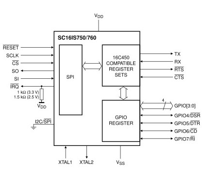
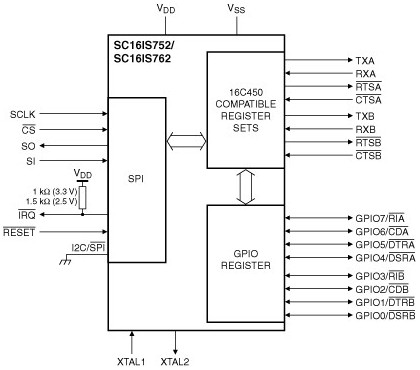
SPI bus operation
The SC16IS750 or SC16IS752 works in SPI bus operation mode when I2C/SPI
set to Low.
|
|
|---|---|
SC16IS750 on SPI bus |
SC16IS752 on SPI bus |
Multiple bridge ICs can be used by connecting the SPI /CS signal to
different outputs of the SPI host controller.
Note
Despite what may be printed on the PCB, when using the SC16IS750 or
SC16IS752 in SPI mode, the SDA pin should be held low or open,
not high. Otherwise, interrupt handling may not function correctly.
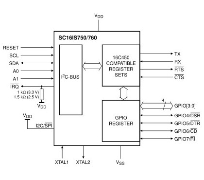
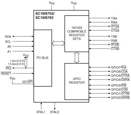
I2C bus operation
The SC16IS750 or SC16IS752 works in I2C bus operation mode when I2C/SPI
set to High.
|
|
|---|---|
SC16IS750 on I2C bus |
SC16IS752 on I2C bus |
Multiple bridge ICs can be operated on a single I2C host controller by
correctly wiring the I2C address select pins A0 and A1. See the
following table.
A1 |
A2 |
raw address |
8-bit address |
7-bit address (shifted) |
|---|---|---|---|---|
VDD |
VDD |
1001 000X |
0x90 |
0x48 |
VDD |
VSS |
1001 001X |
0x92 |
0x49 |
VDD |
SCL |
1001 010X |
0x94 |
0x4A |
VDD |
SDA |
1001 011X |
0x96 |
0x4B |
VSS |
VDD |
1001 100X |
0x98 |
0x4C |
VSS |
VSS |
1001 101X |
0x9A |
0x4D |
VSS |
SCL |
1001 110X |
0x9C |
0x4E |
VSS |
SDA |
1001 111X |
0x9E |
0x4F |
SCL |
VDD |
1010 000X |
0xA0 |
0x50 |
SCL |
VSS |
1010 001X |
0xA2 |
0x51 |
SCL |
SCL |
1010 010X |
0xA4 |
0x52 |
SCL |
SDA |
1010 011X |
0xA6 |
0x53 |
SDA |
VDD |
1010 100X |
0xA8 |
0x54 |
SDA |
VSS |
1010 101X |
0xAA |
0x55 |
SDA |
SCL |
1010 110X |
0xAC |
0x56 |
SDA |
SDA |
1010 111X |
0xAE |
0x57 |
Supported Shields
Single-channel UART/GPIO bridge
OBSOLETE and UNSUPPORTED, use BOB-09981 instead!
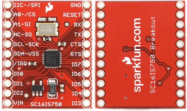
The BOB-09745 [7] is the original breakout board from SparkFun in the early first revision v1.2 with a 12.2880MHz crystal. This revision is not supported by this shield abstraction, as a crystal is populated with an unsuitable value!
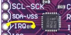
Warning
The board contains a design defect resulting in the interrupt pin
(/IRQ) of the SC16IS750 not being physically connected to the
board outputs.
See also: https://github.com/sparkfun/SC16IS750_Breakout/issues/1
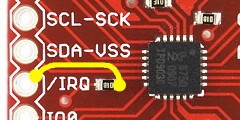
However, this error can be fixed by soldering a small wire bridge
from pin 11 (/IRQ) of the SC16IS750, or rather the one side of
the related pull-up resistor, to the pin header directly to the
left side of it. See the enclosed illustration.
SUPPORTED but FAULTY HARDWARE
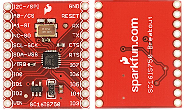
The BOB-09981 [4] is the original breakout board from SparkFun in the redesigned revision v1.3 with a 14.7456MHz crystal to allow baud rates from 9600 up to 921600.
Warning
The board contains a design defect resulting in the interrupt pin
(/IRQ) of the SC16IS750 not being physically connected to the
board outputs.
See also: https://github.com/sparkfun/SC16IS750_Breakout/issues/1
However, this error can be fixed by soldering a small wire bridge
from pin 11 (/IRQ) of the SC16IS750, or rather the one side of
the related pull-up resistor, to the pin header directly to the
left side of it. See the enclosed illustration.
SUPPORTED but FAULTY HARDWARE
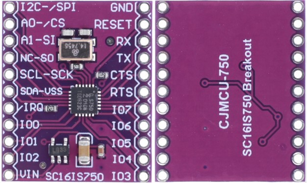
The CJMCU-750 [1] is a widely used clone based on the original SparkFun breakout board and has the exact same design flaws!
Warning
The unconnected interrupt line was copied from the faulty original
design, the interrupt pin (/IRQ) of the SC16IS750 not being
physically connected to the board outputs.
See also: https://github.com/sparkfun/SC16IS750_Breakout/issues/1
However, this error can be fixed by soldering a small wire bridge
from pin 11 (/IRQ) of the SC16IS750, or rather the one side of
the related pull-up resistor, to the pin header directly to the
left side of it. See the enclosed illustration.
SUPPORTED (best choice)
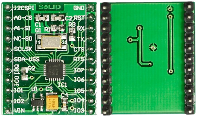
The GT-SC16IS750 [3] is a very rare clone based on the original SparkFun breakout board, but with the missing interrupt line fixed! This copy corresponds to the design revision v1.4 from SparkFun.
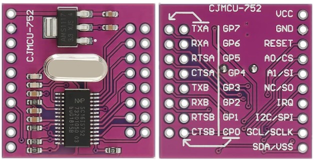
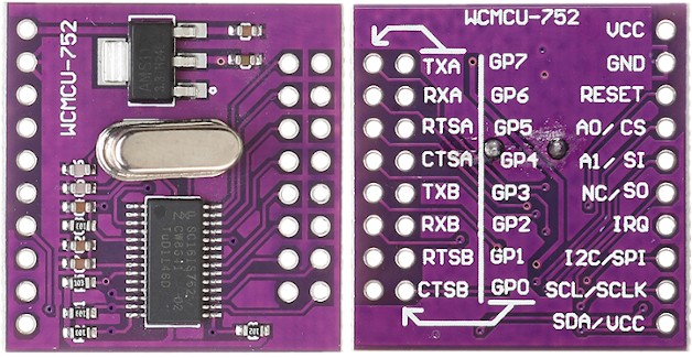
Dual-channel UART/GPIO bridge
Derived from the single-channel breakout board, the new development from CJMCU (Changjiang Intelligent Technology Co., Ltd.) [1] and its clones with an SC16IS752 are also supported. These feature a dual-channel UART/GPIO bridge. All this boards coming with a 1.8432MHz crystal. There are no circuit documents for any of the dual-channel breakout boards.
Utilization
The shield abstraction of these breakout boards is deliberately kept small.
It is purely for evaluating the necessary drivers and Devicetree bindings
on known integration platforms. Due to the large number of clones and the
associated PCB designations and product names, only two basic shield names
are used and extended by the respective short name of the serial peripheral
bus to be used. A special case is the suffix _noirq. This is necessary
if a faulty single-channel breakout board without interrupt line is to
be used. The various connectors on the single and dual channel boards are
generally defined using their own Nyxus header bindings:
I2C shield names |
SPI shield names |
DTS header bindings |
|
|---|---|---|---|
SC16IS750 |
cjmcu_750_i2ccjmcu_750_i2c_noirq |
cjmcu_750_spicjmcu_750_spi_noirq |
|
SC16IS752 |
cjmcu_752_i2ccjmcu_752_i2c_noirq |
cjmcu_752_spicjmcu_752_spi_noirq |
This shields can be used with any development board or shield that provides
a Devicetree node with the cjmcu,75x-hif-header property in
the compatibility. That is needed for GPIO mapping of the reset and optional
interrupt line. Users can rely on the CJMCU-75x Interconnection Shield or create
their own interconnection shields with the necessary mappings in them.
Programming
west build -b nucleo_f746zg -p always --shield "x_cjmcu_75x cjmcu_750_spi" -d build/cjmcu_750 bridle/samples/helloshell
west flash -d build/cjmcu_750
Interrupt disabled
west build -b nucleo_f746zg -p always --shield "x_cjmcu_75x cjmcu_750_spi_noirq" -d build/cjmcu_750 bridle/samples/helloshell
west flash -d build/cjmcu_750
west build -b nucleo_f746zg -p always --shield "x_cjmcu_75x cjmcu_750_i2c" -d build/cjmcu_750 bridle/samples/helloshell
west flash -d build/cjmcu_750
Interrupt disabled
west build -b nucleo_f746zg -p always --shield "x_cjmcu_75x cjmcu_750_i2c_noirq" -d build/cjmcu_750 bridle/samples/helloshell
west flash -d build/cjmcu_750
west build -b nucleo_f746zg -p always --shield "x_cjmcu_75x cjmcu_752_spi" -d build/cjmcu_752 bridle/samples/helloshell
west flash -d build/cjmcu_752
Interrupt disabled
west build -b nucleo_f746zg -p always --shield "x_cjmcu_75x cjmcu_752_spi_noirq" -d build/cjmcu_752 bridle/samples/helloshell
west flash -d build/cjmcu_752
west build -b nucleo_f746zg -p always --shield "x_cjmcu_75x cjmcu_752_i2c" -d build/cjmcu_752 bridle/samples/helloshell
west flash -d build/cjmcu_752
Interrupt disabled
west build -b nucleo_f746zg -p always --shield "x_cjmcu_75x cjmcu_752_i2c_noirq" -d build/cjmcu_752 bridle/samples/helloshell
west flash -d build/cjmcu_752