CJMCU-75x Interconnection Shield
Overview
This shield is less a plug-on module in the conventional sense than more a wiring for interconnection of certain signals from a board down to the SC16IS75x Breakout Boards.
Requirements
This shield requires a board which provides a configuration that allows:
two GPIO lines, 1st for reset output and 2nd for optional interrupt input
one SPI interface, COPI for output and CIPO for input
one I2C interfaces, SDA and SCL for peripheral
Supported variations
The table below suggests shield variation often found on many development boards:
Connector Standard |
Shield Designation |
Variation |
|---|---|---|
Without standard |
needs board adaption |
1 |
2 |
||
(not yet, planned) |
3 |
Arduino Uno (R3) headers
The connector standard Arduino UNO R3 can be used with a variety of
development boards that provide it. Any of these boards must be added
separately. For example, the file boards/nucleo_f746zg.overlay exists for
the Nucleo F746ZG and simply integrates the generally
valid interface boards/arduino_to_cjmcu_if.dtsi:
1#include "arduino_to_cjmcu_if.dtsi"
Serial Bus and GPIO Mapping
I2C Host Interface |
SPI Host Interface |
|---|---|
arduino_to_cjmcu_if.dtsi: I2C serial bus mapping
1cjmcu_i2c: &arduino_i2c {};
arduino_to_cjmcu_if.dtsi: I2C host interface GPIO mapping
 1/ {
 2	cjmcu_hif_i2c: cjmcu-75x-hif-i2c-pins {
 3		compatible = "cjmcu,75x-hif-header";
 4		#gpio-cells = <2>;
 5		gpio-map-mask = <0xffffffff 0xffffffc0>;
 6		gpio-map-pass-thru = <0 0x3f>;
 7		gpio-map = <0 0 &arduino_header 20 0>,	/* SDA @ D18 (D14) */
 8			   <1 0 &arduino_header 21 0>,	/* SCL @ D19 (D14) */
 9			   /* 2: I2C/nSPI signal set to high (VCC) */
10			   <3 0 &arduino_header 15 0>,	/* nIRQ @ D9 */
11			   /* 4: NC/SO signal not connected */
12			   /* 5: A1/SI signal set to I2C addr. select */
13			   /* 6: A0/CS signal set to I2C addr. select */
14			   <7 0 &arduino_header 14 0>;	/* nRESET @ D8 */
15	};
16};
|
arduino_to_cjmcu_if.dtsi: SPI serial bus mapping
1cjmcu_spi: &arduino_spi {};
arduino_to_cjmcu_if.dtsi: SPI host interface GPIO mapping
 1/ {
 2	cjmcu_hif_spi: cjmcu-75x-hif-spi-pins {
 3		compatible = "cjmcu,75x-hif-header";
 4		#gpio-cells = <2>;
 5		gpio-map-mask = <0xffffffff 0xffffffc0>;
 6		gpio-map-pass-thru = <0 0x3f>;
 7		gpio-map = /* 0: SDA/NC signal not connected */
 8			   <1 0 &arduino_header 19 0>,	/* SCLK @ D13 (SCK) */
 9			   /* 2: I2C/nSPI signal set to low (GND) */
10			   <3 0 &arduino_header 15 0>,	/* nIRQ @ D9 */
11			   <4 0 &arduino_header 18 0>,	/* SO @ D12 (CIPO) */
12			   <5 0 &arduino_header 17 0>,	/* SI @ D11 (COPI) */
13			   <6 0 &arduino_header 16 0>,	/* CS @ D10 (SS) */
14			   <7 0 &arduino_header 14 0>;	/* nRESET @ D8 */
15	};
16};
|
Interconnection
Arduino Uno (R3) |
|||
|---|---|---|---|
3V3 |
VCC |
||
3V3 |
2 |
for I2C |
|
A0 / D14 |
0 |
||
A1 / D15 |
1 |
||
A2 / D16 |
2 |
||
A3 / D17 |
3 |
||
A4 / D18 / SDA |
4 / 20 |
0 |
SDA |
A5 / D19 / SCL |
5 / 21 |
1 |
SCL |
D0 |
6 |
||
D1 |
7 |
||
D2 |
8 |
||
D3 |
9 |
||
D4 |
10 |
||
D5 |
11 |
||
D6 |
12 |
||
D7 |
13 |
||
D8 |
14 |
7 |
nRESET |
D9 |
15 |
3 |
nIRQ |
D10 / SS |
16 |
6 |
CS |
D11 / COPI |
17 |
5 |
SI |
D12 / CIPO |
18 |
4 |
SO |
D13 / SCK |
19 |
1 |
SCLK |
GND |
2 |
for SPI |
|
GND |
GND |
Sample Prototypes
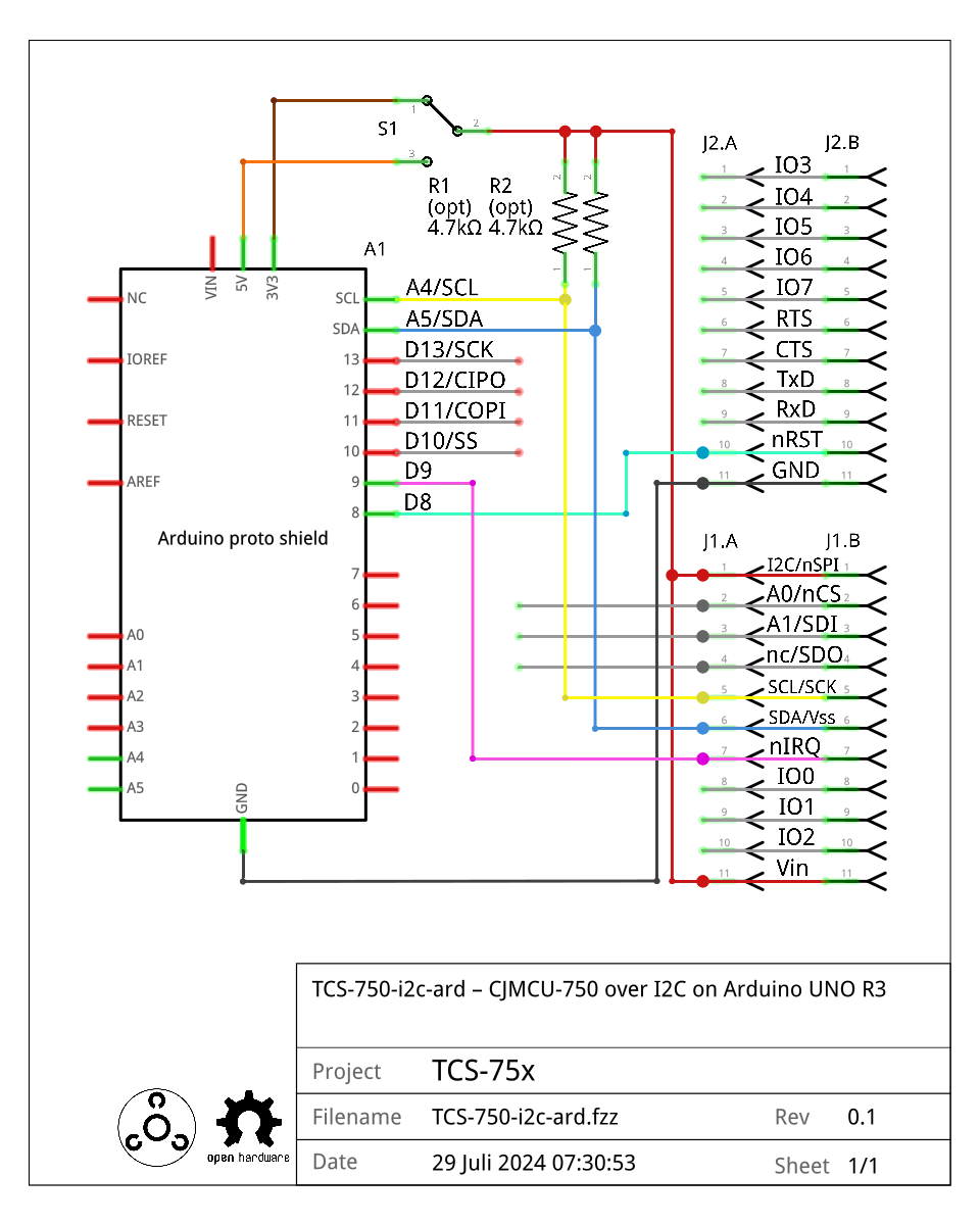
Fritzing project file:
TCS-750-i2c-ard.fzz
Schematic (not for production) |
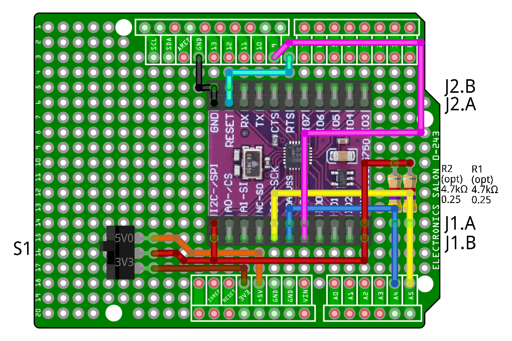
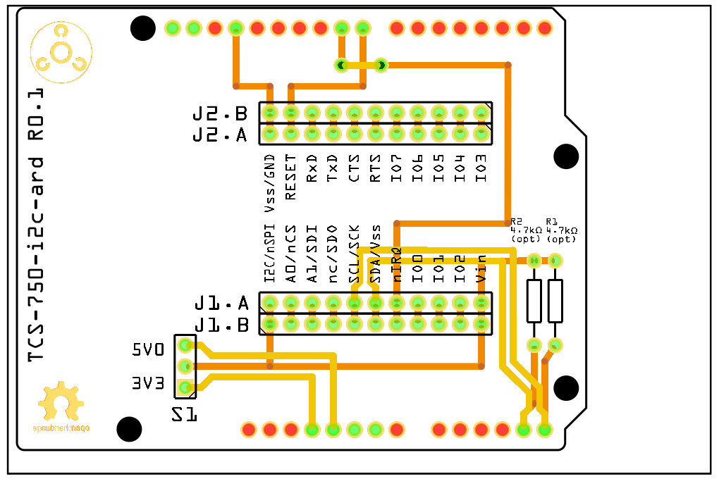
Prototype and Printed Circuit Board |
|
|
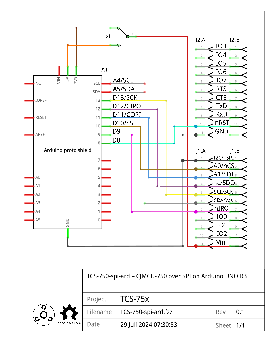
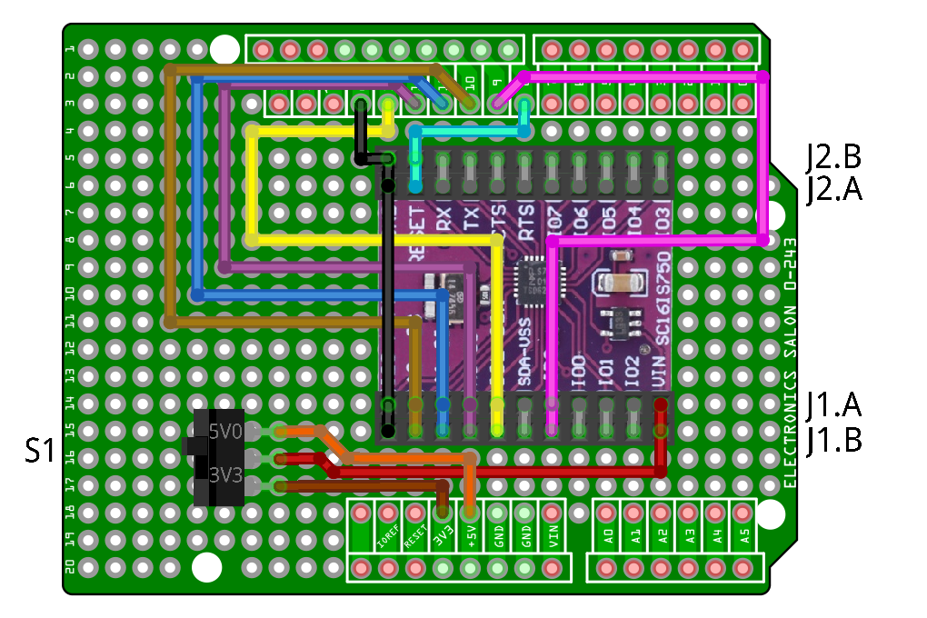
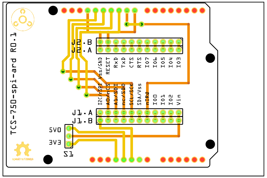
Fritzing project file:
TCS-750-spi-ard.fzz
Schematic (not for production) |
Prototype and Printed Circuit Board |
|
|
Mikro BUS headers
Note
The connector standard MikroBus is not yet supported
and has yet to be defined.