Waveshare RP2040-LCD-0.96
The RP2040 SoC [37] by Raspberry Pi Ltd. is a small sized and low-cost 32-bit dual ARM Cortex-M0+ microcontroller and predestined for versatile board designs. The Waveshare RP2040 board series based on this microcontroller offers a wide range with different scaling factors, in size, features and interfaces for communication, input and output.
Board Overview
Hardware
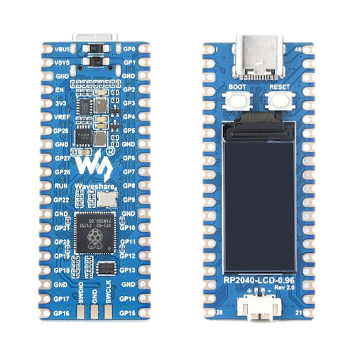
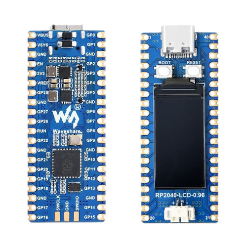
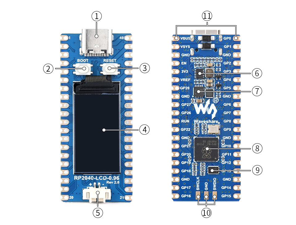
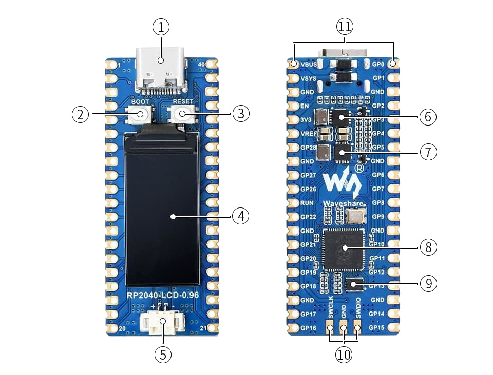
The RP2040-LCD-0.96 [21] is a pico sized RP2040 development board. The on-board USB-C connector makes it compatible to future standards. It comes with an on-board 0.96-inch IPS display, a Lithium battery charger and higher current high-efficiency DC-DC buck-boost converter. The edge pin layout is compatible to the original Raspberry Pi Pico.
Features and Resources |
Printed Circuit Board |
5V/1.1A 3.3V/1.8A 3.3V(OUT) 3.3V(EN/PS) 133㎒ 2㎆ 264㎅ RST BL LCD USB-C UF2 SWD 26 16 3 2 2 2
Design Data
|
|
Positions
|
|---|
|
|
|---|
|
Data Sheets
Flash partitions
QSPI NOR-Flash |
bootrom |
code_partition |
storage_partition |
|---|---|---|---|
primary 2㎆ |
256B |
1㎆ - 256B |
1㎆ |
Pinouts
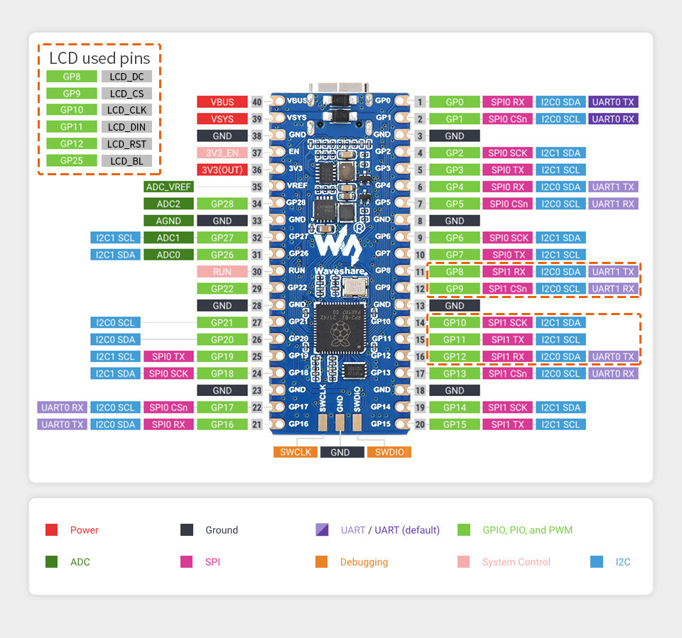
The peripherals of the RP2040 SoC [37] can be routed to various pins on the board. The configuration of these routes can be modified through DTS. Please refer to the datasheet to see the possible routings for each peripheral. The default assignments for the board is defined below.
External pin mapping on the RP2040-LCD-0.96 is identical to the original Raspberry Pi Pico board, but note that internal RP2040 GPIO lines 23 and 24 are routed to the voltage regulator and USB connector for SMPS (TPS63000) power saving modes and USB VBUS sense. GPIO line 25 is routed to the on-board user LCD backlight and GPIO line 29 will be used for VSYS/3 voltage monitoring per default.
In addition, GPIO lines 8 to 12 are used for control and SPI communication with the on-board LCD, but are still available externally in parallel.
Pin Mapping |
Pinout |
Default Zephyr Peripheral Mapping
Devicetree compatible |
|
Supported Features
Similar to the Raspberry Pi Pico the board configuration supports the following hardware features:
Peripheral |
Kconfig option |
Devicetree compatible |
Zephyr API |
|---|---|---|---|
PINCTRL |
|||
GPIO |
|||
UART |
|||
UDC (USB Device Controller) |
|||
I2C |
|||
SPI |
|||
PWM |
|||
ADC |
|||
Temperature (Sensor) |
|||
RTC |
|||
Timer (Counter) |
|||
Watchdog Timer (WDT) |
|||
Flash |
|||
PIO |
N/A |
||
UART (PIO) |
|||
SPI (PIO) |
|||
DMA |
|||
HWINFO |
N/A |
||
VREG |
|||
RESET |
|||
CLOCK |
|||
NVIC |
N/A |
Nested Vector Interrupts Controller |
|
SYSTICK |
N/A |
Other hardware features are not currently supported by Zephyr. The default configuration can be found in the different Kconfig files:
Board Configurations
The board can be configured for the following different use cases.
west build -b waveshare_rp2040_lcd_0_96
Use the serial port UART0 on edge header as Zephyr console and for the shell.
west build -b waveshare_rp2040_lcd_0_96 -S usb-console
Use the native USB device port with CDC-ACM as Zephyr console and for the shell.
Connections and IOs
The Waveshare wiki [20] has detailed information about board connections. Download the different schematics or datasheets as linked above per board for more details. The pinout diagrams can also be found there.
System Clock
The RP2040 [37] MCU is configured to use the 12㎒ external crystal with the on-chip PLL generating the 125㎒ system clock. The internal AHB and APB units are set up in the same way as the upstream Raspberry Pi Pico C/C++ SDK [12] libraries.
GPIO (PWM) Ports
The RP2040 [37] MCU has 1 GPIO cell which covers all I/O pads and
8 PWM function unit each with 2 channels beside a dedicated Timer unit. The
channel PWM4 B is available on the on-board backlight LED. All channels of PWM0
until PWM7 are available on the Raspberry Pi Pico header.
ADC/TS Ports
The RP2040 [37] MCU has 1 ADC with 4 channels and an additional
fifth channel for the on-chip temperature sensor (TS). The ADC channels 0-2
are available on the Raspberry Pi Pico header. ADC channel 3 will be used
for internal on-board voltage monitoring.
The external voltage reference ADC_VREF is directly connected to the 3.3V power supply.
SPI Port
The RP2040 [37] MCU has 2 SPIs. To the edge connectors SPI0 is
usable for external devices over GP19 (MOSI), GP16 (MISO), GP18 (SCK), and
GP17 (CSn) on the Raspberry Pi Pico header. SPI1 will be used for internal
on-board LCD as write only half duplex interface over GP11 (MOSI), GP10 (SCK),
and GP9 (CSn), but is also prepared for reconfiguration as an alternative
interface to external devices over GP11 (MOSI), GP12 (MISO), GP10 (SCK),
and GP9 (CSn) on the Raspberry Pi Pico header.
I2C Port
The RP2040 [37] MCU has 2 I2Cs. The default serial bus I2C0 and
the alternative I2C1 are usable for external devices over GP4 (I2C0_SDA),
GP5 (I2C0_SCL), GP14 (I2C1_SDA), and GP15 (I2C1_SCL) on the Raspberry Pi Pico
header.
Serial Port
The RP2040 [37] MCU has 2 UARTs. One of the UARTs (UART0) is
connected to external devices over GP0 (TX) and GP1 (RX) on the Raspberry Pi Pico header, optional with full featured EIA 232D handshake signals, and
is the Zephyr console. UART1 is not available in any default setup.
USB Device Port
The RP2040 [37] MCU has a (native) USB device port that can be used to communicate with a host PC. See the USB sample applications for more, such as the USB CDC ACM UART sample sample which sets up a virtual serial port that echos characters back to the host PC. As an alternative to the default Zephyr console on serial port the Bridle USB Console Snippet (usb-console) can be used to enable CDC ACM and switch the console to USB:
USB device idVendor=2e8a, idProduct=000a, bcdDevice= 4.05
USB device strings: Mfr=1, Product=2, SerialNumber=3
Product: RP2040-LCD-0.96 (CDC ACM)
Manufacturer: Waveshare (Raspberry Pi)
SerialNumber: B69F8448A6E91514
To integrate specific USB device functions that do not follow a USB standard class, the following alternate identifier numbers are available for the various Waveshare RP2040 and RP2350 boards according to the Raspberry Pi USB product ID list [10]:
RP2040
0x101F:0x1020:0x1021:0x1039:RP2040-LCD-1.28
0x103A:0x1044:Power Management HAT (B)
0x1055:0x1056:0x1057:RP2040-Touch-LCD-1.28
0x1083:RP2040-PiZero
0x1084:0x1085:0x1086:RP2040-BLE
0x1087:PICO-Cam-A
RP2350
0x10B0:RP2350-Zero
0x10B1:RP2350-Plus
0x10B2:RP2350-Tiny
0x10B3:RP2350-LCD-1.28
0x10B4:RP2350-Touch-LCD-1.28
0x10B5:RP2350-One
0x10B6:RP2350-Geek
0x10B7:RP2350-LCD-0.96
0x10C3:RP2350-ETH
Programmable I/O (PIO)
The RP2040 SoC [37] comes with two PIO periherals. These are two simple co-processors that are designed for I/O operations. The PIOs run a custom instruction set, generated from a custom assembly language. PIO programs are assembled using pioasm, a tool provided by Raspberry Pi. Further information can be found in the Raspberry Pi Pico C/C++ SDK [12] document, section with title “Using PIOASM, the PIO Assembler”.
Zephyr does not (currently) assemble PIO programs. Rather, they should be manually assembled and embedded in source code. An example of how this is done can be found at drivers/serial/uart_rpi_pico_pio.c or drivers/spi/spi_rpi_pico_pio.c.
Programming and Debugging
Flashing
Using UF2
If you don’t have an SWD adapter, you can flash the board with a UF2 file.
By default, building an app for this board will generate a
build/zephyr/zephyr.uf2 file. If the board is powered on with
the BOOTSEL button pressed, it will appear on the host as a mass
storage device:
USB device idVendor=2e8a, idProduct=0003, bcdDevice= 1.00
USB device strings: Mfr=1, Product=2, SerialNumber=0
Product: RP2 Boot
Manufacturer: Raspberry Pi
SerialNumber: E0C9125B0D9B
The UF2 file should be drag-and-dropped or copied on command line to the device, which will then flash the board.
RP2040 Boot-ROM
Each RP2040 SoC [37] ships the UF2 compatible [6] bootloader pico-bootrom-rp2040 [14], a native support in silicon. The full source for the RP2040 bootrom at pico-bootrom-rp2040 [14] includes versions B0, B1 and B2 of the bootrom, which correspond to the same silicon revisions, respectively.
Note that every time you build a program for the RP2040, the Pico SDK selects
an appropriate second stage bootloader based on what kind of external QSPI
Flash type the board configuration you are building for was giving. There
are several versions of boot2 [13] for different flash chips, and each one is
exactly 256 bytes of code which is put right at the start of the eventual
program binary. On Zephyr the boot2 versions are part of the
Raspberry Pi Pico HAL [19] module. Possible selections:
CONFIG_RP2_FLASH_AT25SF128A:CONFIG_RP2_FLASH_GENERIC_03H:CONFIG_RP2_FLASH_IS25LP080:CONFIG_RP2_FLASH_W25Q080:CONFIG_RP2_FLASH_W25X10CL:
The board set this option to CONFIG_RP2_FLASH_W25Q080.
Further information can be found in the RP2040 Datasheet [38], sections with title “Bootrom” and “Processor Controlled Boot Sequence” or Brian Starkey’s Blog article Pico serial bootloader [18]
Using SEGGER JLink
You can flash the board with a SEGGER JLink debug probe as described in Building, Flashing and Debugging.
Here is an example of building and flashing the Blinky application.
west build -b waveshare_rp2040_lcd_0_96/rp2040 -p -d build/waveshare_rp2040_lcd_0_96 zephyr/samples/basic/blinky
west flash -r jlink -d build/waveshare_rp2040_lcd_0_96
Using OpenOCD
To use PicoProbe [15] or Raspberry Pi Debug Probe [16], you must configure
udev. Create a file in /etc/udev.rules.d with any name,
and write the line below:
ATTRS{idVendor}=="2e8a", ATTRS{idProduct}=="0004", MODE="660", GROUP="plugdev", TAG+="uaccess"
ATTRS{idVendor}=="2e8a", ATTRS{idProduct}=="000c", MODE="660", GROUP="plugdev", TAG+="uaccess"
This example is valid for the case that the user joins to plugdev
groups.
The board has an SWD interface that can be used to program and debug the on-board RP2040. This interface can be utilized by OpenOCD. To use it with the RP2040, OpenOCD version 0.12.0 or later is needed. If you are using a Debian based system (including RaspberryPi OS, Ubuntu, and more), using the pico_setup.sh [17] script is a convenient way to set up the forked version of OpenOCD. Depending on the interface used (such as JLink), you might need to checkout to a branch that supports this interface, before proceeding. Build and install OpenOCD as described in the README.
Here is an example of building and flashing the Blinky application.
west build -b waveshare_rp2040_lcd_0_96/rp2040 -p -d build/waveshare_rp2040_lcd_0_96 zephyr/samples/basic/blinky -- \
-DOPENOCD=/usr/local/bin/openocd \
-DOPENOCD_DEFAULT_PATH=/usr/local/share/openocd/scripts \
-DWAVESHARE_RP2040_DEBUG_ADAPTER=picoprobe
west flash -r openocd -d build/waveshare_rp2040_lcd_0_96
Set the environment variables OPENOCD to
/usr/local/bin/openocd and OPENOCD_DEFAULT_PATH to
/usr/local/share/openocd/scripts. This should work with the OpenOCD
that was installed with the default configuration. This configuration also
works with an environment that is set up by the pico_setup.sh [17] script.
WAVESHARE_RP2040_DEBUG_ADAPTER specifies what debug adapter is
used for debugging. If WAVESHARE_RP2040_DEBUG_ADAPTER was not
assigned, cmsis-dap is used by default. The other supported adapters
are picoprobe, raspberrypi-swd, jlink and
blackmagicprobe. How to connect picoprobe and
raspberrypi-swd is described in Getting Started Guide with Raspberry
Pi Pico [11]. Any other SWD debug adapter maybe also work with this configuration.
The value of WAVESHARE_RP2040_DEBUG_ADAPTER is cached, so it can
be omitted from west flash and west debug if it was
previously set while running west build.
WAVESHARE_RP2040_DEBUG_ADAPTER is used in an argument to OpenOCD as
"source [find interface/${WAVESHARE_RP2040_DEBUG_ADAPTER}.cfg]". Thus,
WAVESHARE_RP2040_DEBUG_ADAPTER needs to be assigned the file name of
the debug adapter.
You can also flash the board with the following command that directly calls OpenOCD (assuming a SEGGER JLink adapter is used):
$ openocd -f interface/jlink.cfg    \
          -c 'transport select swd' \
          -f target/rp2040.cfg      \
          -c "adapter speed 2000"   \
          -c 'targets rp2040.core0' \
          -c 'program path/to/zephyr.elf verify reset exit'
Debugging
The SWD interface can also be used to debug the board. To achieve this, you can either use SEGGER JLink or OpenOCD.
Using SEGGER JLink
Use a SEGGER JLink debug probe and follow the instruction in Building, Flashing and Debugging.
Using OpenOCD
Install OpenOCD as described for flashing the board.
Here is an example for debugging the Blinky application.
west build -b waveshare_rp2040_lcd_0_96/rp2040 -p -d build/waveshare_rp2040_lcd_0_96 zephyr/samples/basic/blinky -- \
-DOPENOCD=/usr/local/bin/openocd \
-DOPENOCD_DEFAULT_PATH=/usr/local/share/openocd/scripts \
-DWAVESHARE_RP2040_DEBUG_ADAPTER=raspberrypi-swd
west debug -d build/waveshare_rp2040_lcd_0_96
As with flashing, you can specify the debug adapter by specifying WAVESHARE_RP2040_DEBUG_ADAPTER at west build time. No needs to specify it at west debug time.
You can also debug with OpenOCD and gdb launching from command-line. Run the following command:
$ openocd -f interface/jlink.cfg    \
          -c 'transport select swd' \
          -f target/rp2040.cfg      \
          -c "adapter speed 2000"   \
          -c 'targets rp2040.core0'
On another terminal, run:
$ gdb-multiarch
Inside gdb, run:
(gdb) tar ext :3333
(gdb) file path/to/zephyr.elf
You can then start debugging the board.
Basic Samples
LED Blinky and Fade
LCD Backlight LED Blinky by GPIO
See also Zephyr sample: Blinky.
west build -b waveshare_rp2040_lcd_0_96/rp2040 -p -d build/waveshare_rp2040_lcd_0_96 zephyr/samples/basic/blinky -- -DCONFIG_REGULATOR_GPIO=n
west flash -d build/waveshare_rp2040_lcd_0_96
LCD Backlight LED Blinky by PWM
See also Zephyr sample: PWM Blinky.
west build -b waveshare_rp2040_lcd_0_96/rp2040 -p -d build/waveshare_rp2040_lcd_0_96 zephyr/samples/basic/blinky_pwm -- -DCONFIG_REGULATOR_GPIO=n
west flash -d build/waveshare_rp2040_lcd_0_96
LCD Backlight LED Fade by PWM
See also Zephyr sample: Fade LED.
west build -b waveshare_rp2040_lcd_0_96/rp2040 -p -d build/waveshare_rp2040_lcd_0_96 zephyr/samples/basic/fade_led -- -DCONFIG_REGULATOR_GPIO=n
west flash -d build/waveshare_rp2040_lcd_0_96
Hello Shell with USB-CDC/ACM Console
Hello Shell
See also Bridle sample: Hello Shell.
west build -b waveshare_rp2040_lcd_0_96/rp2040 -p -S "usb-console" -d build/waveshare_rp2040_lcd_0_96 bridle/samples/helloshell
west flash -d build/waveshare_rp2040_lcd_0_96
Simple test execution on target
(text in bold is a command input)
uart:~$ hello -h
hello - say hello
uart:~$ hello
Hello from shell.
uart:~$ hwinfo devid
Length: 8
ID: 0x803ef4cd7a1ad186

uart:~$ kernel version
Zephyr version 4.5.0-rc2

uart:~$ bridle version
Bridle version 4.4.99

uart:~$ bridle version long
Bridle version 4.4.99.0

uart:~$ bridle info
Zephyr: 4.5.0-rc2
Bridle: 4.4.99
uart:~$ device list
devices:
- clock-controller@40008000 (READY)
  DT node labels: clocks
- reset-controller@4000c000 (READY)
  DT node labels: reset
- snippet_cdc_acm_console_uart (READY)
  DT node labels: snippet_cdc_acm_console_uart
- timer@40054000 (READY)
  DT node labels: timer
- uart@40034000 (READY)
  DT node labels: uart0 rpipico_serial pico_serial
- watchdog@40058000 (READY)
  DT node labels: wdt0
- dma@50000000 (READY)
  DT node labels: dma
- gpio-port@0 (READY)
  DT node labels: gpio0
- usbd@50110000 (READY)
  DT node labels: usbd zephyr_udc0
- adc@4004c000 (READY)
  DT node labels: adc
- flash-controller@18000000 (READY)
  DT node labels: ssi
- i2c@40044000 (READY)
  DT node labels: i2c0 pico_i2c0 pico_i2c rpipico_i2c0 rpipico_i2c
- pwm@40050000 (READY)
  DT node labels: pwm
- vreg@40064000 (READY)
  DT node labels: vreg
- rtc@4005c000 (READY)
  DT node labels: rtc
- lcd-backlight-en (READY)
  DT node labels: lcd_backlight_en
- dietemp (READY)
  DT node labels: die_temp
uart:~$ history
[  0] history
[  1] device list
[  2] bridle info
[  3] bridle version long
[  4] bridle version
[  5] kernel version
[  6] hwinfo devid
[  7] hello
[  8] hello -h
Operate with the on-chip voltage regulator unit:
uart:~$ regulator vlist vreg
0.800000 V
0.850000 V
0.900000 V
0.950000 V
1.000000 V
1.050000 V
1.100000 V
1.150000 V
1.200000 V
1.250000 V
1.300000 V
uart:~$ regulator vget vreg
1.100000 V
Trigger a power-off/on sequence:
uart:~$ hwinfo reset_cause
reset caused by:
- pin

uart:~$ regulator disable vreg
*** Booting Zephyr OS build v4.5.0-rc2…***
Hello World! I'm THE SHELL from waveshare_rp2040_lcd_0_96
uart:~$ hwinfo reset_cause
reset caused by:
- power-on reset
Operate with the on-board LCD backlight switch as voltage regulator:
uart:~$ regulator vlist lcd-backlight-en
3.300000 V
0 uV
uart:~$ regulator vget lcd-backlight-en
3.300000 V
The off/on sequence:
uart:~$ regulator vset lcd-backlight-en 0V
uart:~$ regulator vset lcd-backlight-en 3300mV
Operate with the on-board LCD backlight switch LCD_BL at GP25 as GPIO:
uart:~$ gpio get gpio0 LCD_BL_PWM9
0

uart:~$ gpio conf gpio0 LCD_BL_PWM9 oh0

uart:~$ gpio set gpio0 LCD_BL_PWM9 1
uart:~$ gpio set gpio0 LCD_BL_PWM9 0

uart:~$ gpio blink gpio0 LCD_BL_PWM9
Hit any key to exit
Get an overview of aviliable signale names:
uart:~$ gpio info gpio0
 ngpios: 30
 Reserved pin mask: 0x00000000

 Reserved  Pin  Line Name
            0    TX0
            1    RX0
            2    GP2_CTS0
            3    GP3_RTS0
            4    SDA0
            5    SCL0
            6    GP6
            7    GP7
            8    LCD_DC
            9    LCD_CSN1
           10    LCD_SCK1
           11    LCD_SDO1
           12    LCD_RST
           13    GP13
           14    GP14_SDA1
           15    GP15_SCL1
           16    SDI0
           17    CSN0
           18    SCK0
           19    SDO0
           20    GP20_PWM4
           21    GP21_PWM5
           22    GP22_PWM6
           23    PSU_SMPS
           24    PSU_VBUS/1.51
           25    LCD_BL_PWM9
           26    ADC0
           27    ADC1
           28    ADC2
           29    PSU_ADC3_VSYS/3
Operate with the channels:
on-board voltage monitor on channel ADC_CH3
on-chip temperature sensor on channel ADC_CH4
uart:~$ adc adc@4004c000 resolution 12
uart:~$ adc adc@4004c000 print
adc@4004c000:
Gain: 1
Reference: INTERNAL
Acquisition Time: 0
Channel ID: 0
Differential: 0
Resolution: 12
uart:~$ adc adc@4004c000 read 3
read: 2062
uart:~$ adc adc@4004c000 read 4
read: 749
Operate with the on-chip RTC unit:
uart:~$ rtc get rtc
RTC not set
uart:~$ rtc set rtc 2024-11-23T18:37:55

uart:~$ rtc get rtc
2024-11-23T18:37:59.000
Operate with the on-chip timer unit:
uart:~$ timer oneshot timer 0 1000000
timer: Alarm triggered
Erase, Write and Verify
uart:~$ flash read ssi 0xe0000 0x40
000E0000: ff ff ff ff ff ff ff ff  ff ff ff ff ff ff ff ff |........ ........|
000E0010: ff ff ff ff ff ff ff ff  ff ff ff ff ff ff ff ff |........ ........|
000E0020: ff ff ff ff ff ff ff ff  ff ff ff ff ff ff ff ff |........ ........|
000E0030: ff ff ff ff ff ff ff ff  ff ff ff ff ff ff ff ff |........ ........|

uart:~$ flash test ssi 0xe0000 0x1000 2
Erase OK.
Write OK.
Verified OK.
Erase OK.
Write OK.
Verified OK.
Erase-Write-Verify test done.
uart:~$ flash read ssi 0xe0000 0x40
000E0000: 00 01 02 03 04 05 06 07  08 09 0a 0b 0c 0d 0e 0f |........ ........|
000E0010: 10 11 12 13 14 15 16 17  18 19 1a 1b 1c 1d 1e 1f |........ ........|
000E0020: 20 21 22 23 24 25 26 27  28 29 2a 2b 2c 2d 2e 2f | !"#$%&' ()*+,-./|
000E0030: 30 31 32 33 34 35 36 37  38 39 3a 3b 3c 3d 3e 3f |01234567 89:;<=>?|

uart:~$ flash page_info 0xe0000
Page for address 0xe0000:
start offset: 0xe0000
size: 4096
index: 224
uart:~$ flash erase ssi 0xe0000 0x1000
Erase success.

uart:~$ flash read ssi 0xe0000 0x40
000E0000: ff ff ff ff ff ff ff ff  ff ff ff ff ff ff ff ff |........ ........|
000E0010: ff ff ff ff ff ff ff ff  ff ff ff ff ff ff ff ff |........ ........|
000E0020: ff ff ff ff ff ff ff ff  ff ff ff ff ff ff ff ff |........ ........|
000E0030: ff ff ff ff ff ff ff ff  ff ff ff ff ff ff ff ff |........ ........|
The RP2040-LCD-0.96 has no on-board I2C devices. For this example the Grove Temperature and Barometer Sensor – BMP280 [24] was connected.
uart:~$ i2c scan pico_i2c
     0  1  2  3  4  5  6  7  8  9  a  b  c  d  e  f
00:             -- -- -- -- -- -- -- -- -- -- -- --
10: -- -- -- -- -- -- -- -- -- -- -- -- -- -- -- --
20: -- -- -- -- -- -- -- -- -- -- -- -- -- -- -- --
30: -- -- -- -- -- -- -- -- -- -- -- -- -- -- -- --
40: -- -- -- -- -- -- -- -- -- -- -- -- -- -- -- --
50: -- -- -- -- -- -- -- -- -- -- -- -- -- -- -- --
60: -- -- -- -- -- -- -- -- -- -- -- -- -- -- -- --
70: -- -- -- -- -- -- -- 77
1 devices found on pico_i2c
The I2C address 0x77 is a Bosch BMP280 Air Pressure Sensor and their
Chip-ID can read from register 0xd0. The Chip-ID must be 0x58:
uart:~$ i2c read_byte pico_i2c 77 d0
Output: 0x58
uart:~$ sensor info
device name: dietemp, vendor: Raspberry Pi Foundation, model: pico-temp, friendly name: RP2040 chip temperature
on-chip temperature sensor
uart:~$ sensor get dietemp
channel type=12(die_temp) index=0 shift=5 num_samples=1 value=25086603304ns (50.823357)
More Samples
Display Test and Demonstration
The following samples work with the chosen display. That is:
chosen { zephyr,display = &lcd_panel; };lcd_panel: &st7735s_160x80 {};LCD Orientation and Bit Order Test
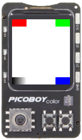
Draw some basic rectangles onto the display using the Display driver API. See also Zephyr sample: Display.
west build -b waveshare_rp2040_lcd_0_96/rp2040 -p -S "usb-console" -d build/waveshare_rp2040_lcd_0_96 zephyr/samples/drivers/display
west flash -d build/waveshare_rp2040_lcd_0_96
|
|---|
TOP LEFT, TOP RIGHT, BOTTOM RIGHT |
LVGL Basic Sample
Displays “Hello World!” in the center of the screen and a counter at the bottom which increments every second using the LVGL module on top of the Display driver API. See also Zephyr sample: LVGL basic sample.
west build -b waveshare_rp2040_lcd_0_96/rp2040 -p -S "usb-console" -d build/waveshare_rp2040_lcd_0_96 zephyr/samples/subsys/display/lvgl
west flash -d build/waveshare_rp2040_lcd_0_96
This sample comes with a Shell command line access to the LVGL backend on the console, here configured for a USB console:
Simple test execution on target
uart:~$ lvgl
lvgl - LVGL shell commands
Subcommands:
  stats   : Show LVGL statistics
  monkey  : LVGL monkey testing

uart:~$ lvgl stats
stats - Show LVGL statistics
Subcommands:
  memory  : Show LVGL memory statistics
            Usage: memory [-c]
                   -c  dump chunk information

uart:~$ lvgl stats memory
Heap at 0x20001520 contains 2047 units in 11 buckets

  bucket#    min units        total      largest      largest
             threshold       chunks      (units)      (bytes)
  -----------------------------------------------------------
        0            1            1            1            8
        1            2            3            3           24
       10         1024            1         1138         9104

9148 free bytes, 6716 allocated bytes, overhead = 516 bytes (3.2%)
uart:~$ device list
devices:
- clock-controller@40008000 (READY)
  DT node labels: clocks
- reset-controller@4000c000 (READY)
  DT node labels: reset
- snippet_cdc_acm_console_uart (READY)
  DT node labels: snippet_cdc_acm_console_uart
- timer@40054000 (READY)
  DT node labels: timer
- uart@40034000 (READY)
  DT node labels: uart0 pico_serial rpipico_serial
- watchdog@40058000 (READY)
  DT node labels: wdt0
- dma@50000000 (READY)
  DT node labels: dma
- gpio-port@0 (READY)
  DT node labels: gpio0
- usbd@50110000 (READY)
  DT node labels: usbd zephyr_udc0
- pwm@40050000 (READY)
  DT node labels: pwm
- vreg@40064000 (READY)
  DT node labels: vreg
- spi@40040000 (READY)
  DT node labels: spi1 pico_spi1 rpipico_spi1
- spi@4003c000 (READY)
  DT node labels: spi0 pico_spi0 pico_spi rpipico_spi0 rpipico_spi
- lcd-backlight-en (READY)
  DT node labels: lcd_backlight_en
- mipi-dbi-spi1 (READY)
  DT node labels: mipi_dbi_spi1
- st7735s-160x80@0 (READY)
  DT node labels: st7735s_160x80 lcd_panel