Waveshare RP2040-Zero
The RP2040 SoC [31] by Raspberry Pi Ltd. is a small sized and low-cost 32-bit dual ARM Cortex-M0+ microcontroller and predestined for versatile board designs. The Waveshare RP2040 board series based on this microcontroller offers a wide range with different scaling factors, in size, features and interfaces for communication, input and output.
Board Overview
Hardware
The RP2040-Zero [17] is a mini sized RP2040 development board. The on-board USB-C connector makes it compatible to future standards. The castellated module allows soldering direct to carrier boards.
Features and Resources |
Printed Circuit Board |
5V/480㎃ 3.3V/800㎃ 3.3V(OUT) 133㎒ 2㎆ 264㎅ RST RGB USB-C UF2 20+9 16 4 2 1 1
Design Data
|
|
Positions
|
|---|
|
Data Sheets
Flash partitions
QSPI NOR-Flash |
bootrom |
code_partition |
storage_partition |
|---|---|---|---|
primary 2㎆ |
256B |
1㎆ - 256B |
1㎆ |
Pinouts
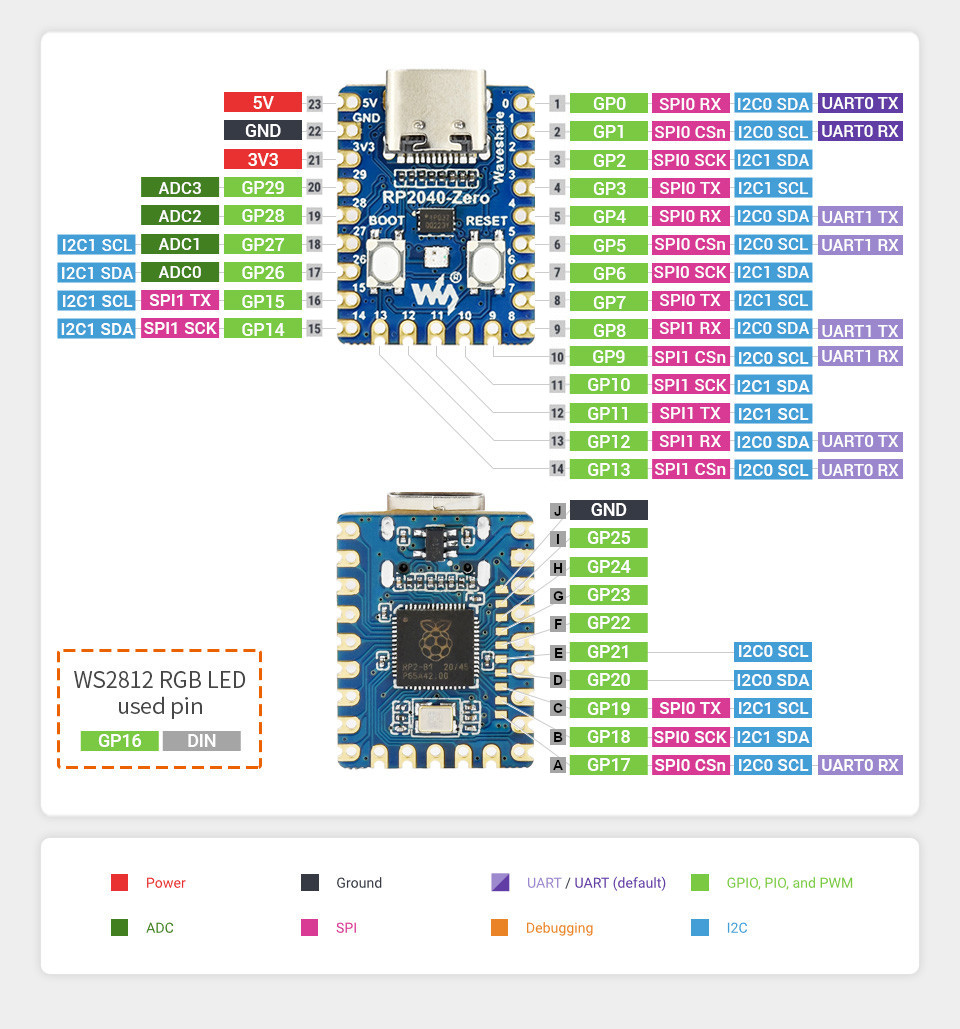
The peripherals of the RP2040 SoC [31] can be routed to various pins on the board. The configuration of these routes can be modified through DTS. Please refer to the datasheet to see the possible routings for each peripheral. The default assignments for the board is defined below.
External pin mapping on the RP2040-Zero is not identical to the original Raspberry Pi Pico board. Almost all pins are rearranged in a more compact order. Likewise, the voltage sense and monitoring functions are not integrated. Thus all internal R2040 GPIO lines are available for free use, insofar there is sufficient space for them on the outer edge of the board or on the bottom side by additional solder points.
Only GPIO line 16 is exclusively routed to the on-board user RGB LED. The analog voltage reference is internally hard-wired to the digital 3.3V power supply and only decoupled by a simple resistor. There is no option to change this from outside the board.
Pin Mapping |
Pinout |
Default Zephyr Peripheral Mapping
Devicetree compatible |
|
Supported Features
Similar to the Raspberry Pi Pico the board configuration supports the following hardware features:
Peripheral |
Kconfig option |
Devicetree compatible |
Zephyr API |
|---|---|---|---|
PINCTRL |
|||
GPIO |
|||
UART |
|||
UDC (USB Device Controller) |
|||
I2C |
|||
SPI |
|||
PWM |
|||
ADC |
|||
Temperature (Sensor) |
|||
RTC |
|||
Timer (Counter) |
|||
Watchdog Timer (WDT) |
|||
Flash |
|||
PIO |
N/A |
||
UART (PIO) |
|||
SPI (PIO) |
|||
DMA |
|||
HWINFO |
N/A |
||
VREG |
|||
RESET |
|||
CLOCK |
|||
NVIC |
N/A |
Nested Vector Interrupts Controller |
|
SYSTICK |
N/A |
Other hardware features are not currently supported by Zephyr. The default configuration can be found in the different Kconfig files:
Board Configurations
The board can be configured for the following different use cases.
west build -b waveshare_rp2040_zero
Use the serial port UART0 on edge header as Zephyr console and for the shell.
west build -b waveshare_rp2040_zero -S usb-console
Use the native USB device port with CDC-ACM as Zephyr console and for the shell.
Connections and IOs
The Waveshare wiki [16] has detailed information about board connections. Download the different schematics or datasheets as linked above per board for more details. The pinout diagrams can also be found there.
System Clock
The RP2040 [31] MCU is configured to use the 12㎒ external crystal with the on-chip PLL generating the 125㎒ system clock. The internal AHB and APB units are set up in the same way as the upstream Raspberry Pi Pico C/C++ SDK [11] libraries.
GPIO (PWM) Ports
The RP2040 [31] MCU has 1 GPIO cell which covers all I/O pads and 8 PWM function unit each with 2 channels beside a dedicated Timer unit. Only 13 PWM channels are available on the edge connectors, but not supported in default configuration. There is also no internal on-board component that requires or use any PWM functionality.
ADC/TS Ports
The RP2040 [31] MCU has 1 ADC with 4 channels and an additional
fifth channel for the on-chip temperature sensor (TS). The ADC channels 0-3
are available on the Waveshare RP2040 Mini header.
The external voltage reference ADC_VREF is directly connected to the 3.3V power supply.
SPI Port
The RP2040 [31] MCU has 2 SPIs. To the edge connectors SPI0 is
usable for external devices over GP7 (MOSI), GP4 (MISO), GP6 (SCK), and
GP5 (CSn) on the Waveshare RP2040 Mini header. SPI1 is not available
in any default setup.
I2C Port
The RP2040 [31] MCU has 2 I2Cs. The default serial bus I2C0 is
usable for external devices over GP8 (I2C0_SDA) and GP9 (I2C0_SCL). I2C1 is
not available in any default setup, but could be configured to GP14 (I2C1_SDA)
and GP15 (I2C1_SCL) on the Waveshare RP2040 Mini header.
Serial Port
The RP2040 [31] MCU has 2 UARTs. One of the UARTs (UART0) is
connected to external devices over GP0 (TX) and GP1 (RX) on the Waveshare RP2040 Mini header, optional with full featured EIA 232D handshake signals,
and is the Zephyr console. UART1 is not available in any default setup.
USB Device Port
The RP2040 [31] MCU has a (native) USB device port that can be used to communicate with a host PC. See the USB sample applications for more, such as the USB CDC ACM UART sample sample which sets up a virtual serial port that echos characters back to the host PC. As an alternative to the default Zephyr console on serial port the Bridle USB Console Snippet (usb-console) can be used to enable CDC ACM and switch the console to USB:
USB device idVendor=2e8a, idProduct=000a, bcdDevice= 4.05
USB device strings: Mfr=1, Product=2, SerialNumber=3
Product: RP2040-Zero (CDC ACM)
Manufacturer: Waveshare (Raspberry Pi)
SerialNumber: B69F8448A6E91514
To integrate specific USB device functions that do not follow a USB standard class, the following alternate identifier numbers are available for the various Waveshare RP2040 and RP2350 boards according to the Raspberry Pi USB product ID list [10]:
RP2040
0x101F:0x1020:0x1021:0x1039:RP2040-LCD-1.28
0x103A:0x1044:Power Management HAT (B)
0x1055:0x1056:0x1057:RP2040-Touch-LCD-1.28
0x1083:RP2040-PiZero
0x1084:0x1085:0x1086:RP2040-BLE
0x1087:PICO-Cam-A
RP2350
0x10B0:RP2350-Zero
0x10B1:RP2350-Plus
0x10B2:RP2350-Tiny
0x10B3:RP2350-LCD-1.28
0x10B4:RP2350-Touch-LCD-1.28
0x10B5:RP2350-One
0x10B6:RP2350-Geek
0x10B7:RP2350-LCD-0.96
0x10C3:RP2350-ETH
Programmable I/O (PIO)
The RP2040 SoC [31] comes with two PIO periherals. These are two simple co-processors that are designed for I/O operations. The PIOs run a custom instruction set, generated from a custom assembly language. PIO programs are assembled using pioasm, a tool provided by Raspberry Pi. Further information can be found in the Raspberry Pi Pico C/C++ SDK [11] document, section with title “Using PIOASM, the PIO Assembler”.
Zephyr does not (currently) assemble PIO programs. Rather, they should be manually assembled and embedded in source code. An example of how this is done can be found at drivers/serial/uart_rpi_pico_pio.c or drivers/spi/spi_rpi_pico_pio.c.
Programming and Debugging
Flashing
The board can only be flashed with a UF2 file. There is no SWD connector.
Using UF2
By default, building an application for the board will generate a
build/zephyr/zephyr.uf2 file. If the board is powered on with
the BOOTSEL button pressed, it will appear on the host as a mass
storage device:
USB device idVendor=2e8a, idProduct=0003, bcdDevice= 1.00
USB device strings: Mfr=1, Product=2, SerialNumber=0
Product: RP2 Boot
Manufacturer: Raspberry Pi
SerialNumber: E0C9125B0D9B
The UF2 file should be drag-and-dropped or copied on command line to the device, which will then flash the board.
RP2040 Boot-ROM
Each RP2040 SoC [31] ships the UF2 compatible [6] bootloader pico-bootrom-rp2040 [13], a native support in silicon. The full source for the RP2040 bootrom at pico-bootrom-rp2040 [13] includes versions B0, B1 and B2 of the bootrom, which correspond to the same silicon revisions, respectively.
Note that every time you build a program for the RP2040, the Pico SDK selects
an appropriate second stage bootloader based on what kind of external QSPI
Flash type the board configuration you are building for was giving. There
are several versions of boot2 [12] for different flash chips, and each one is
exactly 256 bytes of code which is put right at the start of the eventual
program binary. On Zephyr the boot2 versions are part of the
Raspberry Pi Pico HAL [15] module. Possible selections:
CONFIG_RP2_FLASH_AT25SF128A:CONFIG_RP2_FLASH_GENERIC_03H:CONFIG_RP2_FLASH_IS25LP080:CONFIG_RP2_FLASH_W25Q080:CONFIG_RP2_FLASH_W25X10CL:
The board set this option to CONFIG_RP2_FLASH_W25Q080.
Further information can be found in the RP2040 Datasheet [32], sections with title “Bootrom” and “Processor Controlled Boot Sequence” or Brian Starkey’s Blog article Pico serial bootloader [14]
Debugging
The board does not provide any SWD connector, thus debugging software is not possible.
Basic Samples
LED Blinky and Fade
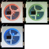
WS2812 LED Test Pattern by PIO
See also Zephyr sample: LED strip.
west build -b waveshare_rp2040_zero/rp2040 -p -d build/waveshare_rp2040_zero zephyr/samples/drivers/led/led_strip -- -DCONFIG_SAMPLE_LED_UPDATE_DELAY=500
west flash -d build/waveshare_rp2040_zero
Hint
Neither LED Blinky nor LED Fade can be built and executed on this board, because this system has only one digital RGB LED. A simple GPIO or PWM control is not possible!
Hello Shell with USB-CDC/ACM Console
Hello Shell
See also Bridle sample: Hello Shell.
west build -b waveshare_rp2040_zero/rp2040 -p -S "usb-console" -d build/waveshare_rp2040_zero bridle/samples/helloshell
west flash -d build/waveshare_rp2040_zero
Simple test execution on target
(text in bold is a command input)
uart:~$ hello -h
hello - say hello
uart:~$ hello
Hello from shell.
uart:~$ hwinfo devid
Length: 8
ID: 0x9b91758914c92fe9

uart:~$ kernel version
Zephyr version 4.5.0-rc2

uart:~$ bridle version
Bridle version 4.4.99

uart:~$ bridle version long
Bridle version 4.4.99.0

uart:~$ bridle info
Zephyr: 4.5.0-rc2
Bridle: 4.4.99
uart:~$ device list
devices:
- clock-controller@40008000 (READY)
  DT node labels: clocks
- reset-controller@4000c000 (READY)
  DT node labels: reset
- snippet_cdc_acm_console_uart (READY)
  DT node labels: snippet_cdc_acm_console_uart
- timer@40054000 (READY)
  DT node labels: timer
- uart@40034000 (READY)
  DT node labels: uart0 rp2040mini_serial
- watchdog@40058000 (READY)
  DT node labels: wdt0
- pio@50200000 (READY)
  DT node labels: ((pio_hw_t *)0x50200000u)
- dma@50000000 (READY)
  DT node labels: dma
- gpio-port@0 (READY)
  DT node labels: gpio0
- usbd@50110000 (READY)
  DT node labels: usbd zephyr_udc0
- adc@4004c000 (READY)
  DT node labels: adc
- flash-controller@18000000 (READY)
  DT node labels: ssi
- i2c@40044000 (READY)
  DT node labels: i2c0 rp2040mini_i2c
- pwm@40050000 (READY)
  DT node labels: pwm
- vreg@40064000 (READY)
  DT node labels: vreg
- rtc@4005c000 (READY)
  DT node labels: rtc
- pio-ws2812 (READY)
- ws2812 (READY)
  DT node labels: ws2812 led_strip
- dietemp (READY)
  DT node labels: die_temp
uart:~$ history
[  0] history
[  1] device list
[  2] bridle info
[  3] bridle version long
[  4] bridle version
[  5] kernel version
[  6] hwinfo devid
[  7] hello
[  8] hello -h
Operate with the on-chip voltage regulator unit:
uart:~$ regulator vlist vreg
0.800000 V
0.850000 V
0.900000 V
0.950000 V
1.000000 V
1.050000 V
1.100000 V
1.150000 V
1.200000 V
1.250000 V
1.300000 V
uart:~$ regulator vget vreg
1.100000 V
Trigger a power-off/on sequence:
uart:~$ hwinfo reset_cause
reset caused by:
- pin

uart:~$ regulator disable vreg
*** Booting Zephyr OS build v4.5.0-rc2…***
Hello World! I'm THE SHELL from waveshare_rp2040_zero
uart:~$ hwinfo reset_cause
reset caused by:
- power-on reset
Operate with the RGB digital LED strip 1 RGB at PIO0 / GP16:
uart:~$ led_strip get_length led_strip
ws2812 has 1 pixel(s)
Sett all LEDs to RED:
uart:~$ led_strip fill led_strip 070000 1
Sett all LEDs to YELLOW:
uart:~$ led_strip fill led_strip 070700 1
Sett all LEDs to GREEN:
uart:~$ led_strip fill led_strip 000700 1
Sett all LEDs to CYAN:
uart:~$ led_strip fill led_strip 000707 1
Sett all LEDs to BLUE:
uart:~$ led_strip fill led_strip 000007 1
Sett all LEDs to MAGENTA:
uart:~$ led_strip fill led_strip 070007 1
Sett all LEDs to WHITE (all on):
uart:~$ led_strip fill led_strip 070707 1
Sett all LEDs to BLACK (all off):
uart:~$ led_strip fill led_strip 000000 1
Get an overview of aviliable signale names:
uart:~$ gpio info gpio0
 ngpios: 30
 Reserved pin mask: 0xC0010000

 Reserved  Pin  Line Name
            0    TX0
            1    RX0
            2    GP2_CTS0
            3    GP3_RTS0
            4    SDI0
            5    CSN0
            6    SCK0
            7    SDO0
            8    SDA0
            9    SCL0
           10    GP10_PWM10
           11    GP11_PWM11
           12    GP12_PWM12
           13    GP13_PWM13
           14    GP14_SDA1
           15    GP15_SCL1
     *     16
           17    GP17_PWM1
           18    GP18_PWM2
           19    GP19_PWM3
           20    GP20_PWM4
           21    GP21_PWM5
           22    GP22_PWM6
           23    GP23_PWM7
           24    GP24_PWM8
           25    GP25_PWM9
           26    ADC0
           27    ADC1
           28    ADC2
           29    ADC3
Operate with the channels:
on-chip temperature sensor on channel ADC_CH4
uart:~$ adc adc@4004c000 resolution 12
uart:~$ adc adc@4004c000 print
adc@4004c000:
Gain: 1
Reference: INTERNAL
Acquisition Time: 0
Channel ID: 0
Differential: 0
Resolution: 12
uart:~$ adc adc@4004c000 read 4
read: 728
Operate with the on-chip RTC unit:
uart:~$ rtc get rtc
RTC not set
uart:~$ rtc set rtc 2024-11-23T18:37:55

uart:~$ rtc get rtc
2024-11-23T18:37:59.000
Operate with the on-chip timer unit:
uart:~$ timer oneshot timer 0 1000000
timer: Alarm triggered
Erase, Write and Verify
uart:~$ flash read ssi 0xe0000 0x40
000E0000: ff ff ff ff ff ff ff ff  ff ff ff ff ff ff ff ff |........ ........|
000E0010: ff ff ff ff ff ff ff ff  ff ff ff ff ff ff ff ff |........ ........|
000E0020: ff ff ff ff ff ff ff ff  ff ff ff ff ff ff ff ff |........ ........|
000E0030: ff ff ff ff ff ff ff ff  ff ff ff ff ff ff ff ff |........ ........|

uart:~$ flash test ssi 0xe0000 0x1000 2
Erase OK.
Write OK.
Verified OK.
Erase OK.
Write OK.
Verified OK.
Erase-Write-Verify test done.
uart:~$ flash read ssi 0xe0000 0x40
000E0000: 00 01 02 03 04 05 06 07  08 09 0a 0b 0c 0d 0e 0f |........ ........|
000E0010: 10 11 12 13 14 15 16 17  18 19 1a 1b 1c 1d 1e 1f |........ ........|
000E0020: 20 21 22 23 24 25 26 27  28 29 2a 2b 2c 2d 2e 2f | !"#$%&' ()*+,-./|
000E0030: 30 31 32 33 34 35 36 37  38 39 3a 3b 3c 3d 3e 3f |01234567 89:;<=>?|

uart:~$ flash page_info 0xe0000
Page for address 0xe0000:
start offset: 0xe0000
size: 4096
index: 224
uart:~$ flash erase ssi 0xe0000 0x1000
Erase success.

uart:~$ flash read ssi 0xe0000 0x40
000E0000: ff ff ff ff ff ff ff ff  ff ff ff ff ff ff ff ff |........ ........|
000E0010: ff ff ff ff ff ff ff ff  ff ff ff ff ff ff ff ff |........ ........|
000E0020: ff ff ff ff ff ff ff ff  ff ff ff ff ff ff ff ff |........ ........|
000E0030: ff ff ff ff ff ff ff ff  ff ff ff ff ff ff ff ff |........ ........|
The RP2040-Zero has no on-board I2C devices. For this example the Grove Temperature and Barometer Sensor – BMP280 [20] was connected.
uart:~$ i2c scan rp2040mini_i2c
     0  1  2  3  4  5  6  7  8  9  a  b  c  d  e  f
00:             -- -- -- -- -- -- -- -- -- -- -- --
10: -- -- -- -- -- -- -- -- -- -- -- -- -- -- -- --
20: -- -- -- -- -- -- -- -- -- -- -- -- -- -- -- --
30: -- -- -- -- -- -- -- -- -- -- -- -- -- -- -- --
40: -- -- -- -- -- -- -- -- -- -- -- -- -- -- -- --
50: -- -- -- -- -- -- -- -- -- -- -- -- -- -- -- --
60: -- -- -- -- -- -- -- -- -- -- -- -- -- -- -- --
70: -- -- -- -- -- -- -- 77
1 devices found on rp2040mini_i2c
The I2C address 0x77 is a Bosch BMP280 Air Pressure Sensor and their
Chip-ID can read from register 0xd0. The Chip-ID must be 0x58:
uart:~$ i2c read_byte rp2040mini_i2c 77 d0
Output: 0x58
uart:~$ sensor info
device name: dietemp, vendor: Raspberry Pi Foundation, model: pico-temp, friendly name: RP2040 chip temperature
on-chip temperature sensor
uart:~$ sensor get dietemp
channel type=12(die_temp) index=0 shift=5 num_samples=1 value=80000262752ns (35.134804)